April 13, 2016 Lada.Online 208 001 4
Depending on the year of manufacture, different types of instrument panels were installed on the domestic SUV. Until about 1998, Niva 4x4s were equipped with instrument clusters made in Hungary, and after Avtopribor LLC (Vladimir and Podolsk). Let's look at the features of these panels in the diagrams.
Niva 4x4 instrument panel diagrams
Schematic electrical diagrams, connecting devices and pinout of connectors
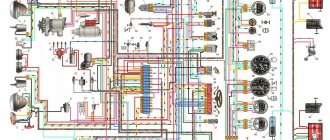
1 – plug connector block with conditional numbering of plugs; 2 – tachometer; 3 – voltage stabilizer; 4 – instrument cluster lighting lamp; 5 – coolant temperature indicator; 6 – fuel level indicator; 7 – resistor 470 Ohm, 0.25 W; 8 – resistor 36 Ohm, 5 W; 9 – warning lamp of the toxicity reduction system;
10 – control lamp for heated rear window; 11 – fog light indicator lamp; 12 – control lamp for high beam headlights; 13 – indicator lamp for external lighting; 14 – indicator lamp for direction indicators; 15 – voltmeter; 16 – brake fluid level warning lamp; 17 – diode IN4002;
1 – tachometer; 2 – voltage stabilizer; 3 – instrument cluster lighting lamp; 4 – coolant temperature indicator; 5 – fuel level indicator; 6 – warning lamp of the toxicity reduction system; 7 – indicator lamp for heated rear window; 8 – fog light indicator lamp;
9 – control lamp for high beam headlights; 10 – indicator lamp for external lighting; 11 – indicator lamp for direction indicators; 12 – voltmeter; 13 – brake fluid level warning lamp; 14 – oil pressure warning lamp; 15 – differential lock warning lamp; 16 – fuel reserve warning lamp;
Let us remind you that on the website you can find reports on the modification or repair of a domestic SUV.
Key words: 4x4 instrument panel
Found an error? Select it and press Ctrl Enter..
- What could Lada Largus be like after restyling?
- How to remove the front bumper on a Lada Kalina
- Lada Vesta SW appeared in the Za Rulem editorial park
- Installing the altmenu on the radio (MMC) Lada Vesta
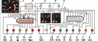
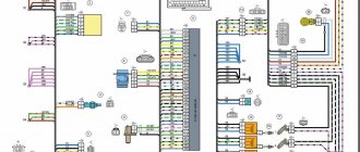
Electrical diagram of VAZ 21214 with distributed fuel injection
| 1. Engine control system warning lamp; 2. Instrument cluster (fragments); 3. Electric fans of the engine cooling system * ; 4. Courtesy light switch located on the driver's door pillar; 5. Car anti-theft system status indicator; 6. Control unit of the automobile anti-theft system; 7. Coolant temperature sensor; 8. Air flow sensor; 9. Throttle assembly; 10. Block connected to the throttle position sensor; 11. Block connected to the idle speed regulator; 12. Controller; 13. Oxygen concentration sensor; 14. Knock sensor; 15. Crankshaft position sensor; | 16. Speed sensor; 17. Adsorber; 18. Battery; 19. Main relay; 20. Diagnostic block;21. engine control system fuse box; 22. relay for turning on the electric fuel pump; 23. relay for turning on electric fans; 24. main car fuse box (fragment); 25. block connected to the additional wiring harness *; 26. ignition module; 27. tachometer; 28. electric fuel pump with fuel level sensor; 29. injectors; 30. spark plugs; |
A – rear wiring harness wire connected to switch 4; B – wires connected to plug “1” of fuse block 24 (one wire goes to plug “15” of the ignition switch, and the other to plug “85” of the ignition relay); B – rear wiring harness wires connected to the fuel level indicator.
The order of conditional numbering of plugs in blocks:
a – controller; b – control unit of the automobile anti-theft system; c – air flow sensor; g – speed sensor; d – indicator of the state of the automobile anti-theft system; e – electric fuel pump and oxygen concentration sensor; g – throttle pipe; h – ignition module.
* Gray wires in block 25 are the vehicle speed signal output, the yellow-red wire is the fuel consumption signal output (for the trip computer).
Installation of the VAZ 2110 dashboard on Lada 4×4 (VAZ 2121, 2131)
Lada 4×4 has been produced for more than 39 years and during this time the interior of the domestic SUV has remained virtually unchanged. However, you can make the car interior more comfortable with the help of various modifications. For example, install a more modern instrument panel from a VAZ 2110 on a Niva.
You will need: a VDO instrument panel with catalog number 21150-3801010, an instrument cluster trim (article: 21214-5325124-00), a speed sensor, for a carburetor Lada 4×4 you also need a gasoline level sensor from the injection system, at least 8 female terminals , wire 0.75 about 10 m.
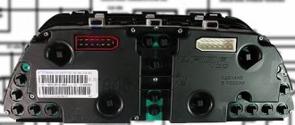
We remove the old dashboard. The white and red blocks of the new instrument panel have a different pinout (see diagram of the Lada 4×4 panel), so the main task is to reconnect the wires in the right order.
Also interesting: How to start a Niva if the battery is dead (5 ways)
| White block number | Old panel | New panel | Color |
| 1 | Empty | Housing (weight) | Black (optional) |
| 2 | High beam warning lamp | Low voltage tachometer input | Brown-red |
| 3 | Dimensions indicator lamp | High voltage tachometer input | Brown |
| 4 | To terminal “15” of the ignition switch | To terminal “30” of the ignition switch | additional from class "30" |
| 5 | To the hazard switch | To the indicator sensor | green |
| 6 | To terminal "D" of the generator | Side light warning lamp | yellow |
| 7 | Empty | Choke (carb models) | Grey |
| 8 | PTF warning lamp | "Check Engine" lamp | black and white |
| 9 | Warning lamp for heated glass | To terminal 15 of the ignition switch | blue |
| 10 | "Check Engine" lamp | To terminal 15 of the ignition switch | Orange |
| 11 | To fuel level sensor | To "VK" parking brake | pink-black |
| 12 | "Check Engine" lamp | To terminal "D" of the generator | brown-white |
| 13 | To the indicator sensor | To oil pressure sensor | gray-blue |
| Red block number | Old panel | New panel | Color |
| 1 | Empty | To air temperature sensor | Additional |
| 2 | To terminal “15” of the ignition switch | To terminal “15” of the ignition switch | Leave |
| 3 | Low voltage tachometer input | Housing (Weight) | Black |
| 4 | To the instrument lighting control | To the instrument lighting control | Leave |
| 5 | High voltage tachometer input | To the right direction indicators | Blue (Optional) |
| 6 | Housing (weight) | To the left direction indicators | Blue-Black (Optional) |
| 7 | To terminal “50” of the lock. (starter) | To brake fluid level sensor | Pink |
| 8 | To the parking brake switch | To the trip computer | |
| 9 | Empty | To speed sensor output | Additional |
| 10 | To the fuel reserve lamp | To fuel level sensor | Rose red |
| 11 | To differential lock sensor | Towards the distant light | Green-black |
| 12 | To oil pressure sensor | To off alarm | |
| 13 | To brake fluid level sensor | To terminal “50” of the ignition switch (starter) | Red-blue |
The differential lock was connected to the choke lamp. For turn signal lamps, additional wires should be laid from the hazard warning button. The wires for heating the rear window (green-red), rear foglights (orange-black) and turn signals (blue-white) remain unused.
We install and connect the speed sensor (the pinout of the sensor is on its plug). We connect the positive wire from the speed sensor to the upper left fuse box, and take the negative wire from the pin that holds the panel. And we bring the signal wire to the instrument panel.
It is worth noting that after installing the instrument cluster from the VAZ 2110 VDO with two windows, we not only get a more modern SUV interior, but also the ability to display the outside temperature, clock and voltmeter on the panel.
By the way, do you know how to tune a VAZ 2110 panel? For example, install an overlay, wells or tint!
Also interesting: Phase sensor Niva Chevrolet symptoms of malfunction, DPRV high signal level
Circuit breakers
The block of protective devices in Niva is a board on which disposable fuses are installed, containing a fuse inside.
Each of them protects one or more electrical circuits from overvoltage. The unit is located in the cabin on the left side. Protective equipment is numbered. So, 1 is responsible for the work:
- windshield washer;
- stove fan;
- cleaners for all headlights;
- heating, wiper and washer for tailgate glass.
Fuse number 2 controls:
- turn signals, their operation in emergency mode, relay-breaker;
- reversing lamps;
- front windshield wipers;
- dashboard indicators (coolant and oil level, carburetor valve position, parking brake);
- indicators of fuel reserve and antifreeze temperature
3-4 – protect the circuit of the left and right high beams, respectively;
5-6 – low beam.
7 – fuse controls the following elements of the Niva electrical circuit:
- dimensions (rear right and left front);
- license plate illumination.
- lighting of the dashboard, cigarette lighter, interior light switches;
- other marker signals.
9 – the fuse is responsible for:
- turn indicator;
- relay-interrupter and alarm indicator;
- contacts for turning on the rear window heater;
- horn;
- socket;
- interior light;
- rear brake light.
- fog light (rear);
- headlight cleaner motor (start, return to initial position).
16 – is responsible for the operation of the cigarette lighter.
Another block is located in the engine compartment. There fuses are responsible for:
Purpose of the device.
A speedometer is installed on the Niva's instrument panel, which is necessary to display the current speed of the car. In the event of a malfunction, driving becomes difficult as most roads have speed limits that must be followed. In addition, a malfunction of the speedometer can affect the calculation of other data by the on-board computer. Based on the DS data, the required fuel consumption is determined and gasoline savings are ensured while idling.
Therefore, it is necessary to carry out diagnostics as soon as possible and identify the cause of the breakdown.
Niva electrical circuit responsible for the equipment built into the front doors
The following is a general breakdown of the electrical equipment of Chevrolet Niva car doors manufactured after 2009. The representation is based on the fact that both sides are almost identical:
- 1/10 – door position limit switches;
- 2/11 – drive of electric window regulator gearboxes;
- 3/12 – plugs for control drives for adjusting the position of rear-view mirrors;
- 4/13 – door lock gearboxes;
- 5/14 – standard terminal blocks for the speaker outputs of the standard acoustic module;
- 6/15 – window switch drives.
Location.
On Niva DS is installed on the gearbox. This allows data to be read only while driving, turning off when the engine is in neutral.
The device itself consists of a plastic case, inside of which electronic components are located. For proper operation, it is placed in close proximity to the shaft. There is a built-in magnetic bar inside the shaft that creates electrical signals when rotated.
The product is quite fragile, so when dismantling or installing you must be extremely careful not to damage its body.
Checking the sensors.
In order to check the DC, you need to have a multimeter, then follow a certain procedure:
- Turn off the sensor.
- We connect the red (positive) probe to the DC contact.
- We connect the black (negative) probe to ground.
- We fix a tube of suitable diameter onto the shaft in order to be able to rotate it.
- We switch the multimeter switch to low voltage measurement mode.
- It is necessary to rotate the shaft and observe the readings: as the speed increases, the readings on the multimeter display will increase. If the readings do not change, the sensor is faulty.
Another method does not require removing the sensor. To do this, you need to jack up one wheel so that it is at a distance from the ground and can rotate freely. After this, you need to connect a multimeter to the DC connectors. You need to rotate the wheel and observe the readings of the device. A change in voltage will also indicate performance.
Tuning options
The choice of options for tuning is not particularly large:
- Install a device from another car. In this case, you will need the services of a qualified electrician, since the connectors will have to be redone. You can also install a digital version of the tidy - it will be more than original.
- As a tuning option, you can install LED bulbs instead of regular ones. Many car owners choose this option because it is less expensive and the easiest to implement.
- Another tuning method is to install original instrument scales on the speedometer, tachometer and other sensors. Moreover, you can buy such scales either ready-made or make them yourself in accordance with your preferences.
Replacement.
To remove the DS, you need to place the car on a level surface. After this, it is best to disconnect the battery terminals to avoid errors in the BC.
Disconnect the wire terminals; to do this, press the plastic lock on the block. After this, use a wrench to unscrew the sensor from its seat. If you cannot unscrew it immediately, it is not recommended to use excessive force. You need to treat the threaded connection with WD-40, wait a few minutes and continue dismantling.
Installation of a new DS is carried out in the reverse order. When purchasing a new part, you need to pay attention to the external condition: the contacts must be treated with a sufficient amount of varnish, as this protects them from moisture. After completing the work, it is necessary to reset the on-board computer errors in order to remove the CHECK ENGINE error.
Also interesting: Chevrolet Niva idle speed sensor
As for its location, look for the DS in the engine compartment in close proximity to the exhaust manifold. To be honest, the place where it is installed cannot be called ideal. While the car is running, the manifold heats up. The sensor wires rub against it, which over time leads to malfunctions and short circuits.
It doesn’t matter whether you have an injection car or a carburetor with a Europanel - the connection of the speed sensor to the instrument cluster is identical.
Replacing the VAZ speed sensor: step-by-step instructions:
- Drive into the pit - it will be more convenient to work from below - and wait until the engine cools down.
- Turn off the vehicle's power by removing the cable from the negative terminal of the battery. Do not close the hood after this, this will provide you with lighting.
- Locate the speed sensor on the transmission. Clean it and everything near it with a rag to remove any dirt.
- By pressing the spring clip, disconnect the wire block from the sensor.
- Dismantle the sensor itself by unscrewing it counterclockwise - with your fingers or an open-end wrench to “22”.
- Carefully, so as not to break anything, install a new part in place of the removed part. Connect the wire block to it and the procedure for replacing the speed sensor can be considered complete.
How to properly connect a new DS? It is important here that the device rod fits correctly into the fixing sleeve, otherwise rotation will not be transmitted to the sensor. If the sensor fits into the socket the first time, then everything is in its place, and if something prevents it from moving, then the rod did not fit into the bushing.
Features of the modification
First of all, the changes affected the engine management system and control instruments. In particular:
- The wiring diagram for Niva 21213 received an additional wiring harness in the engine compartment for connecting a microcontroller and sensors;
- On the Niva model of recent years of production, a more advanced power unit with the VAZ-21214 index is installed. Instead of a carburetor, it has a fuel frame with injectors from GM. The price of a car with injection has increased because of this;
- The instrument panel has changed - the design is borrowed from the VAZ 2108 model.
Ignition system
The VAZ 21213 engine uses a non-contact ignition system consisting of:
- ignition distributor sensor (marking 3810.3706). It is responsible for creating control pulses supplied to the electronic switch;
- switch (model marking – 3620.3734) in climatic version U2.1 (corresponds to GOST 15150);
- ignition coils (marking 27.3705).
For reference: this device provides increased spark energy, which helps start the engine in cold weather, and also improves the performance of the power unit when operating the vehicle on low-quality fuel.
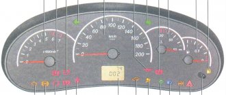
Dashboard
A modified instrument panel appeared on the car. In particular, instead of a voltmeter, the manufacturer installed a low battery discharge lamp (no. 12 in the diagram).
Tip: if you often operate your car in off-road conditions, you can buy and connect a voltmeter to the instrument panel yourself. It is more informative than a warning light and will allow you to identify electrical system faults long before the battery discharges.
How to check the VAZ speed sensor
A failed speedometer sensor in a VAZ car is easily determined - in this case, the speedometer stops working, and it may also show some signs of life, but display incorrect information.
Using a tube, pliers or other available tools, rotate the sensor axis. In this case, you should see the voltmeter readings changing: the higher the speed, the higher the voltage (from 0.5 to 10 V). If this does not happen, the sensor requires replacement.
Niva electrical circuit responsible for the equipment built into the cargo compartment door
- 1 – output of the contact group of the rear bundle of highways;
- 2 – door position limit switch;
- 3 – central locking gearbox;
- 4 – voltage for the rear windshield washer motor;
- 5 – plug for additional brake sign;
- 6 – heated aft windshield;
- 7 – stern glass wiper controller;
- 8 – relay of the above element.