Don’t ask me anything, I wrote everything I know.
You can copy this article to your blog, then notify me so that I can delete this entry.
First type of devices:
Kalinas and Prioras without can tires.
On the VAZ-1118 (Kalina) from 2004 to 2011, the device was installed 1118-3801010
All these devices have a 32-pin connector. You can, for example, install a Priorovskaya tidy instead of a Kalinovskaya one, but it is advisable to select the desired model (1118 or 2170).
Instead of such a tidy, you can install an expensive tidy with navigation 1118-3801010-50 for Kalina and 2112 with Europanel or 2170-3801010-50 s for Prior produced before July 2012 (without CAN bus). And they additionally need a GPS antenna and a wiper switch with a joystick (they are described below).
Addition from Shurik5891
On the first releases of 1118 devices, there are no LEDs for ABS, ESD, or seat belts.
Addition from Shandys
On Kalina1 2013
with e-gas and cable drive gearbox there is a tidy 11180-3801010-20 vdo _____________________________________ Second type of
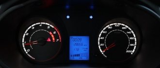
Grant devices of the 1st generation
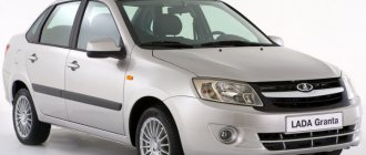
Granta appeared in 2011
From a smart book: “The electronic engine control system of the LADA GRANTA car implements a data exchange interface between the ECM, instrument cluster and diagnostic device via the CAN bus. The CAN bus is a two-wire line: - CAN L low level line (contact “X2/D2” of the ECM - contact “7” of the instrument cluster - contact “14” of the diagnostic block); - CAN H high level line (contact “X2/F1” of the ECM – contact “8” of the instrument cluster – contact “6” of the diagnostic block). The immobilizer is integrated into the instrument cluster." Pinout of devices 2190
: 1 - To the emergency oil pressure sensor, 2 - To the parking brake switch, 3 - Service. Panel diagnostics, 4 — To the exterior lighting switch, 5 — To the right turn signal switch, 6 — To the left turn signal switch, 7 — CAN-L, 8 — CAN-H, 9 — To the seat belt sensor, 10 — “RESET” key » on the steering column switch, 11 - To the brake fluid level sensor, 12 - To the high beam headlights, 13 - To the low beam headlights, 14 - To the rear fog lamp, 15 - To the front fog lamps, 16 - Immobilizer antenna input (b) , 17 — “Ground” panel, 18 — Immobilizer antenna input (a), 19 — To terminal “30,” 20 — To electric power steering, 21 — To terminal “15,” 22 — To door sensor, 23 — MK key “ forward", 24 - MK key "back", 25 - To the outside temperature sensor, 26 - To the fuel level sensor. Instrument clusters are interchangeable.
Pinout provided by fellow teemest
The connector for these devices is 26-pin.
Some devices have sound for turn signals and/or hazard lights, some do not. This is normal and is not a malfunction. Instead of a temperature indicator, there was only a light bulb, the lighting of which indicated overheating. On June 16, 2014, they began installing the device with firmware 092, and in the window it was possible to select engine temperature readings. On cars with the standard configuration, there is no outside temperature sensor. If the device has firmware 090, you can take sensor 2115-3828210, one contact to the body, the second to contact 25 of the devices, and the function of displaying the outside temperature will work. Devices may also differ in the presence/absence of an indicator for front fog lights, an indicator for an automatic transmission, etc. And there are these same devices with navigation.
A detailed article on flashing such devices is here www.drive2.ru/l/6010764/
The third type of devices
Priora 1 with can-bus.
Since July 2012, Priora also began installing devices with a CAN bus. For example, 2170-3801010-30 Addition from turbomotor412
Pinout of CAN panel Priora 1st generation 2170-3801010-30. 1) To the electric power steering, 2) Reserve, 3) Reserve, 4) To the parking brake switch, 5) To the immobilizer control unit (electrical package), 6) Reserve, 7) To the light control module (light on indicator), To the switch turn signal (right side), 9) To the turn switch (left side), 10) CAN_L, 11) CAN_H, 12) Immobilizer antenna (not engaged), 13) Immobilizer antenna (not engaged), 14) To the steering column switch (" button Reset"), 15) To the brake fluid level sensor, 16) Reserve, 17) To the high beam switch, 18) To the light control module (light dimmer), 19) Housing, 20) Terminal “30” of the battery, 21) Terminal “15” of the ignition switch, 22) Reserve, 23) To the steering column switch (down button), 24) To the steering column switch (up button), 25) To the outside temperature sensor, 26) To the outside temperature sensor, 27) To the fuel level sensor, 28) Reserve, 29) Reserve, 30) Reserve, 31) Service. Diagnostics of instrument cluster during production, 32) Reserve
On these devices, the built-in immobilizer is not used, but the immobilizer of the electrical package unit is used, with which the ECU communicates via the k-line. ECU Bosch ME 17.9.7 21126-1411020-45 transitional. Supports both CAN-bus (communication with ABS 9.0, dashboard, airbag unit) and k-line (communication with the immobilizer in the electrical package unit).
The connection pins also change: 2) To the radio receiver “MUTE”, 10) Reserve, 11) To the radio receiver “AUDIO OUT” “-“, 14) To the steering column switch (“Left”, “OK”), 23) To the steering column switch ( “Down”, “Menu”), 24) To the steering column switch (“Right”, “Up”), 25) To the radio receiver “AUDIO OUT” “+”, 28) CAN_L, 29) CAN_H photo of the 2012 Priora connector
Both of these devices potentially support the indication of the ESP system, although in fact no such cars left the assembly line. 2170-3801010-30 has an icon to the left of the screen, and 2170-3801010-60 on the LCD screen.
The fourth type of devices
With can-bus for Priora-2 Pinout of Priora-2 devices: 1 - EUR, 4 - handbrake, 7 - dimensions, 10 - CAN H, 11 - CAN L, 12 and 13 - immobilizer antenna, 14 and 23 and 24 - k steering column switch, 15 — brake reservoir, 18 — backlight, 19 — ground, 20 — constant power, 21 — ignition, 25 and 26 — outside temperature sensor, 27 — fuel level, (28 and 29 — CAN bus for devices with navigation) , 31 - diagnostics.
That is, devices for with a CAN bus, for the Priora-1 generation and another for the Priora-2 generation.
Additions from Oren56ru
: — Since June 2012, the Priora Coupe came with a CAN bus and already began installing devices with navigation. — link to hardware improvements for devices with navigation and Amoled display if it freezes www.drive2.ru/c/2282291/
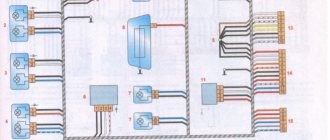
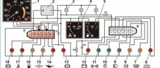
Lada Kalina front harness connections
Diagram 1. Connections of the front wiring harness of the car: 1,2,3,4- blocks of the front wiring harness to the instrument panel wiring harness; 5 — left headlight; 6 — reverse gear lock solenoid; 7 — reverse light switch; 8-starter; 9 - battery; 10-generator; 11 – blocks of the wiring harness of the battery, starter and front wiring harness; 12- right headlight; 13-electric washer motor; 14 – air temperature sensor; 15 beep; 16 - rear window washer motor
How to open the hood of Lada Granta
In order to open the hood of the Lada Grant, you need to pull the lever located on the left under the instrument panel. Then put your hand under the hood just to the left of the middle, press the safety hook lever from the bottom up and lift the hood. Remove the stop from the clips on the front of the car while holding the hood. Lift the stop and insert its curved end into the hole on the inside of the hood. To close the hood, remove the end of the stop from the hole by lifting the hood slightly. Lower the stop and secure it in the clamps
Carefully lower the hood and the safety hook will engage. Press the hood near the lock until it clicks
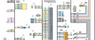
Lada Kalina instrument panel harness connections
Connections of the instrument panel harness: 1.3,4, 5 – blocks of the instrument panel wiring harness to the front wiring harness; 2.6 2.6 — blocks of the instrument panel wiring harness to the rear wiring harness; 7,8,9, 10 – contacts of the mounting block block; 11- lighting control module; 12 — instrument cluster; 13 – heater motor switch; 14 — blocks of the instrument panel wiring harness to the air supply wiring harness; 15 – ignition switch; 16 – anti-theft system block; 17 – block of the instrument panel wiring harness to the ignition system wiring harness; 18 – cigarette lighter; 19 – alarm switch; 20 - rear window heating switch; 21 — stop signal switch; 22 – light signaling switch; 23 – on-board computer mode switch; 24 – wiper switch; 25 – sound signal switch; 26,27 – heating and ventilation control lighting lamps; 28 – lampshade lighting of the glove box; 29 – glove box lighting switch; 30.31 – block of wiring harnesses to the radio; 32 – heater electric motor; 33 – heater resistance; 34 – electric amplifier control unit
Features of connecting BC
In conclusion, I would like to dwell in more detail on such a point as installing an on-board computer. In the typical pinout diagram shown just above, there is only one wire leading to it - brown. But for the correct operation of this device, this alone will not be enough. Therefore, here is a complete pinout diagram for connecting the on-board computer:
- Green wire – comes from the electronic control unit, needed to obtain information about fuel consumption.
- Orange – goes to the ignition switch, to terminal 15.
- White-red - in the same place, only to terminal 30.
- The common ground wire is black.
- Brown – needed to take speed data.
- Red-green - to the positive circuit of the fuel level sensor.
- White - leads to the light control, which is responsible for the lamps that illuminate the instrument panel.
Connection of the wiring harness of the 1.6 l Lada Kalina engine management system (ECM)
Connection of the wiring harness of the engine control system (ECM) VAZ 21114 – 50 (1.6l): 1 – ECU; 2 – diagnostic block; 3 – additional fuse block; 4 – speed sensor; 5 – rough road sensor; 6 – oil pressure warning light sensor; 7 – throttle sensor; 8 – coolant temperature sensor; 9 – coolant temperature indicator sensor; 10 – mass fuel flow sensor; 11 – idle speed regulator; 12 – cooling system electric fan relay; 13 – ignition relay; 14 – fuse 50 A; 15 – electric fuel pump relay; 16 – crankshaft position sensor; 17 – control oxygen sensor; 18 – phase sensor; 19 – knock sensor; 20 – solenoid valve for purge of the adsorber; 21 – electric fan of the cooling system; 22 – diagnostic oxygen sensor; 23 – block of the ignition system wiring harness to the instrument panel harness; 24 – ignition coil; 25 – spark plugs; 26 – nozzles; 27 — block of the ignition system wiring harness to the injector wiring harness; 28- block of the injector wiring harness to the wiring harness to the ignition harness; 29 – block of instrument panel harnesses to the ignition harness; 30 – ignition switch; 31 – mounting block (starter relay); 32 – immobilizer control unit; 33 – contacts of three-terminal blocks of the instrument panel wiring harness and the front wiring harness; 34 – instrument cluster; A – to the positive terminal of the battery; B1, B2, B3 – grounding points; C - to the starter.
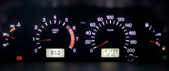
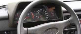
VAZ-2110 dashboard: pinout
Probably, hardly anyone will argue with the fact that the VAZ “ten” is not the pinnacle of design thought.
However, there is nothing surprising here, because this car was designed back in the last century. At the same time, the compensator, and quite a serious one, in this case is the price. In other words, a certain compromise is proposed - the imperfection of the car in exchange for an acceptable cost. Well, the choice is ultimately made by the car owner himself, deciding whether this option is suitable for him. You can talk about the advantages and disadvantages of this model for quite a long time. However, this is not what we will talk about now. Those who decide that the “ten” is a suitable option in terms of the ratio between price and quality often want to somewhat refine their iron horse during operation, making changes to both the exterior and the interior.
If we talk about tuning the car interior, then one of the main objects of improvement here is the dashboard. Many people simply don’t like the native version, which, frankly, doesn’t look very attractive. Yes, after the “Zhiguli” this is an undoubted step forward, but it’s already the 21st century outside the window, and I want something more beautiful and pleasing to the eye.
Wiring diagram of the 1.4 l Lada Kalina engine control system (ECM)
Connection of the wiring harness of the engine control system (ECM) VAZ 11194 (1.4 l): 1 – ECU; 2 — block of the ECU wiring harness to the instrument panel; 3 - main fuse block; 4 — speed sensor; 5 — rough road sensor; 6 — oil pressure drop warning lamp sensor; 7 — throttle position sensor; 8 — coolant temperature sensor; 9 — coolant temperature indicator sensor; 10 — mass air flow sensor; 11 — idle speed regulator; 12 — electric fuel pump relay; 13 — fuel pump fuse (15A); 14 — ignition relay; 15 — ignition relay fuse (15 A); 16 — ECU power supply fuse (7.5A); 17 — crankshaft position sensor; 18 — control oxygen sensor; 19 — phase sensor; 20 — knock sensor; 21 — solenoid valve for purge of the adsorber; 22 — diagnostic oxygen sensor; 23 — ignition coil; 24 — spark plugs; 25 — nozzles; 26 — ignition coil harness block to the ECU; 27 — ECM wiring harness block to the ignition coil wiring harness; 28 — block of the ECM wiring harness to the injector wiring harness; 29 — block of the injector wiring harness to the ECM harness; A – to the positive terminal of the battery; B1, B2, B3 – grounding points of the ignition system harness; C1 is the grounding point for the ignition coil wiring harness.
We activate the front PTF button in the MUS from normal.
We activate the front PTF button in the MUS from normal.
Schematic diagram of the ICC
This modification applies only to the new MUS model, with a vertical connector in a compact thin case.
First, open the ICC.
To remove the low beam and parking light switch, use a cloth or several layers of paper, placing them under the jaws of the pliers, apply a little force, and pull it.
Attention! The latches are filled with glue, carefully release the latches with a straight thin screwdriver or a utility knife
Be careful not to lose the plastic freewheel spring ends.
The ICC has been opened and the board has been removed.
photos of individual areas.
As you can see, the board does not have enough parts to use the PTF button function. Our task is to add them there.
To finalize, we will need to find a relay marked 21.3777MS, namely MS, from the manufacturer ABAR
Attention shortage! The main thing is to make sure that there is an 8-pin AS195 microcircuit on the relay board! datasheet
The main thing is to make sure that there is an 8-pin AS195 microcircuit on the relay board! datasheet
The housing and printed circuit board of the required relay looks something like this (the board is already without components).
If you have the opportunity to open the relay when purchasing, take advantage of it, so as not to buy the wrong relay.
Below are photos of relays that look the same but with a different filling, be careful, you don’t need to buy such relays!
If you find the required relay 21.3777MS (emergency), then solder it from its board to the MUS board:
- chip AS195 DA2A
— transistor BCP56-16 in VT2. - Zener diode BZX 79C 6V2RL in VS1.
SM4005 (1N4001-1N4007 or S1J) in VD6, VD7, VD8, VD9.
HL5 (PTF included, orange).
8.2 kOhm in R28, R24
510 Ohm in R27 910 Ohm in R4
- micro-relay from K1 to K1.
— solder two pins (male) of contacts 3 and 4 of the MUS (taken from the same relay).
— microswitch without fixation, socket SW2.
Photo of the original MUS deluxe board
photo of the upgraded board
my version with wall mounting
Now we need to modify the PTF power button in this way. We make a partition pusher and insert it into special grooves.
We take out the springs from disposable lighters, bite off the constrictions on them, and put them on the guide rods of the button.
We drill a 3mm hole in the button in the same place as on the adjacent one; there is a landmark on the back side.
Press the foil to the hole from the front side. Fill the drilled hole with hot glue, tear off the foil and get a well-filled hole through which the glow from the PTF indication LED will pass.
When assembling the MUS, it is necessary to install the contact group in this way:
To check the result of the modification, we need to apply power to it:
Minus on “31” contact +12V on 30 and Zx then turn the knob on the block to the mode of switching on the dimensions and then you can see what is happening on the diagram (on the MUS board).
If everything is soldered correctly and the parts are all in good condition, then when you press the PTF power button, the small relay on the MUS board should click, and +12 volts should appear on pin 4, close contacts 3 and 4, the indication LED should light up.
I express my deep gratitude to “Andrey710” for their help in the appearance of this article.
Wiring diagram of the rear harness Lada Kalina
Connections of the rear harness of the car: 1 - rear harness block to the instrument panel; 2 — block to the wiring harness of the left front door; 3 - to the rear door wiring harness; 4 — right lamp; 5 - to the rear door wiring harness; 6 — to the tailgate wiring harness; 7 - to the instrument panel; 8 — lampshade; 9 — left side direction indicator; 10 — fuel level indicator sensor; 11 — reverse lock switch; 12 - to the right front door; 13 — parking brake sensor; 14 — trunk light; 15 — double-glazed window control unit; 16 — right direction indicator; 17 — left lamp; 18 - to the tailgate
Electrical diagram of the tailgate and license plate Lada Kalina, numbering of contacts in the mounting block
Electrical diagram of the tailgate and license plate Lada Kalina: 1 - tailgate wiper motor; 2 — additional stop signal; 3, 4 — to the rear wiring harness; 5 — gear motor for locking the luggage compartment lock drive; 6 — luggage compartment lock; 7 — rear window heating element; 8 - to the license plate; 9 — from the lighting lamps to the tailgate harness; 10.11 — license plate light.
The figure on the right shows the numbering of contacts in the mounting block
Replacement and assembly
Installing the right and left switch completely repeats the above steps, but in reverse order: take the part, connect the large and small plugs, and then put the casing in place.
Replacing Kalina steering column switches with a sufficient level of experience and skill can take place in just a few minutes. What other problems may arise in the steering column of the Lada Kalina? For example, your horn may stop working. It helps you communicate with other drivers quickly and efficiently, so a signal failure can be fatal. Therefore, you need to replace the steering column switch connector.