Lada VAZ-2110 (2111, 2112). Electrical circuits - part 1
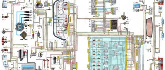
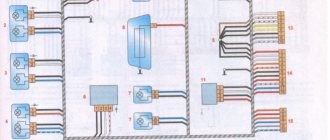
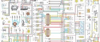
Electrical diagram of the VAZ-2110 car: 1 - block headlight; 2 — front brake pad wear sensors; 3 — fan motor activation sensor; 4 — electric motor of the engine cooling system fan; 5 — sound signal; 6 - generator; 7 — oil level sensor; 8 — carburetor solenoid valve control unit; 9 — heater controller; 10 — recirculation valve switch; 11 — backlight lamp for heater control levers; 12 - switch; 13 — carburetor limit switch; 14 — oil pressure warning lamp sensor; 15 — spark plugs; 16 — carburetor solenoid valve; 17 — coolant temperature indicator sensor; 18 — ignition distributor sensor; 19 — ignition coil; 20 — starter; 21 — heater fan electric motor; 22 — additional resistor of the heater electric motor; 23 — speed sensor; 24 — reverse light switch; 25 — micromotor gearbox for heater damper drive; 26 — recirculation valve; 27 — brake fluid level sensor; 28 — blocks for connecting the rear window washer motor; 29 — battery; 30 — electric motor for windshield washer; 31 — washer fluid level sensor; 32 — coolant level sensor; 33 — windshield wiper gearmotor; 34 — mounting block; 35 — blocks for connecting the warning light harness; 36 — external lighting switch; 37 — instrument cluster; 38 — rear fog light switch; 39 — fog light indicator lamp; 40 — control lamp for heated rear window; 41 — clock; 42 — rear window heating switch;
43 — steering column switch; 44 — block for switching wires when installing headlights of a different type; 45 — instrument lighting regulator; 46 — ignition switch; 47 — blocks for connecting the wiring harness for headlight cleaners; 48 — socket for a portable lamp; 49-front interior lamp; 50 — brake light switch; 51 — interior lamp; 52 — on-board control system unit; 53 — fuel level indicator sensor; 54 — alarm switch; 55 — driver’s seat belt sensor; 56 — cigarette lighter; 57 — ashtray illumination lamp; 58 — switch for the glove compartment lighting lamp; 59 — block for connecting the on-board computer; 60 — glove box lighting lamp; 61 — side direction indicators; 62 — switches in the front door pillars; 63 — switches in the rear door pillars; 64 — parking brake warning lamp switch; 65 — trunk lighting; 66 — temperature sensor for the heating system; 67 — external rear lights; 68 — internal rear lights; 69 — license plate lights; 70 — rear window heating element; 71 — block for connecting an additional brake light. In the instrument panel wiring harness, the second ends of the wires of white, black, orange, white with a red stripe and yellow with a blue stripe are connected to each other at the same points. The electrical circuits of the VAZ-2111 and VAZ-2112 cars differ (with the exception of the engine control system) only in the addition of a tailgate cleaner and washer.
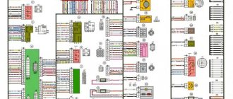
Electrical diagram of a VAZ-21102 car with a distributed fuel injection system ("January-4" controller): 1 - headlight; 2 — front brake pad wear sensors; 3 — sound signal; 4 — cooling system fan; 5- reverse light switch; 6 - battery; 7 - generator; 8 — oil pressure warning lamp sensor; 9 — oil level sensor; 10 — spark plugs; 11 — nozzles; 12 — idle speed regulator; 13 — blocks of the electronic control unit; 14 — throttle position sensor; 15 — crankshaft position sensor; 16 — ignition module; 17 — coolant temperature indicator sensor (for instrument cluster); 18 — starter; 19 — diagnostic block; 20 — coolant temperature sensor (for the engine management system); 21 — speed sensor; 22 — fuel pump activation relay; 23, 35, 39 — fuses; 24 - electric fuel pump; 25 — micromotor gearbox for heater damper drive; 26 — recirculation valve; 27 — heater fan; 28 — windshield washer pump; 29 — washer fluid level sensor; 30 — brake fluid level sensor; 31 — coolant level sensor; 32 — windshield wiper gearmotor; 33 — additional heater fan resistor; 34 — injection system power supply relay; 36 — adsorber purge valve; 37 — mass air flow sensor; 38 — relay for turning on the cooling system fan; 40 — external lighting switch; 41 — knock sensor; 42 - con- sensor
oxygen concentration (heated lambda probe); 42* — CO potentiometer (installed on cars running on leaded gasoline; in this case, an oxygen concentration sensor is not installed); 43 — fog light indicator lamp; 44 — control lamp for heated rear window; 45 — fog light switch; 46 — rear window heating switch; 47 — instrument cluster; 48 — mounting block; 49 — fuel level sensor; 50 — ignition switch; 51 — instrument backlight brightness control; 52 — steering column switch; 53 — backlight lamp for heater control levers; 54 — alarm switch; 55 — electronic heater control unit; 56 — recirculation valve switch; 57 — display unit of the on-board control system; 58 — side direction indicators; 59 — temperature sensor for the heating system; 60 — interior lamp; 61 — front interior lamp; 62 — socket for a portable lamp; 63 — electronic watch; 64 — switches in the front door pillars; 65 — switches in the rear door pillars; 66- glove box lighting lamp; 67 — glove box lighting switch; 68 — cigarette lighter; 69 — ashtray lighting lamp; 70 — brake light switch; 71 — rear window heating element; 72 — external rear lights; 73 — internal rear lights; 74 — license plate lamps; 75 — trunk lighting lamp.
Equipment for VAZ 2112 passenger cars
| Automobile model | VAZ 2112 | VAZ 2112-01 | VAZ 2112-02 |
| Body type | All-metal, monocoque hatchback | ||
| engine's type | 16-valve with distributed fuel injection, V=1500 cm3 | ||
| Execution | "Standard" | "Norm" | "Lux" |
| Option code | 110, 115, 117, 122, 125, 130, 133, 134, 135, 137 GM (s.h.) 10 | 10, 13, 14, 19, 110, 115, 117, 122, 125, 130, 133, 134, 135, 136, 137 | 10, 11, 14, 16, 19, 110, 115, 117, 122, 125, 130, 133, 134, 136, 137 |
| Automobile model | VAZ 21122 | VAZ 21122-01 | VAZ 21122-02 |
| Body type | All-metal, monocoque hatchback | ||
| engine's type | 8-valve with distributed fuel injection, V=1500 cm3 | ||
| Execution | "Standard" | "Norm" | "Lux" |
| Option code | 10, 11, 13, 20, 21, 110, 115, 117, 119, 122, 124, 125, 130, 133, 134, 135, 136, 137 GM (c.c.) 11 | 10, 13, 19, 20, 30, 40, 110, 115, 117, 119, 122, 124, 125, 130, 133, 134, 135, 136, 137 | 10, 11, 16, 19, 20, 30, 40, 110, 115, 117, 119, 122, 124, 125, 130, 133, 134, 135, 137 |
VAZ 2112 diagram
Front part of the diagram
| Position number on the diagram | Explanation of position |
| 1 | Flashlight |
| 2 | brake pad wear sensor (not installed on all cars.) VAZ 2112 |
| 3 | reverse light button |
| 4 | electric radiator fan motor cooling structure |
| 5 | signaling |
| 6 | gear motor for locking the right front door lock (on some cars a gear motor is mounted without the central locking switch turned on) |
| 7 | Relay for switching electric windows (Not installed on all cars.) |
| 8 | starter connection relay |
| 9 | starter |
| 10 | electricity storage |
| 11 | Magneto VAZ 2112 |
| 12 | electric windshield washer pump |
| 13 | low antifreeze level meter |
| 14 | gear motor for locking the left front door (on some cars a central locking switch is mounted) |
| 15 | left front door power window switch (Not installed on all passenger cars.) |
| 16 | low antifreeze level meter (Not mounted on all machines.) |
| 17 | windshield wiper gear motor |
| 18 | electric and pneumatic recirculation throttle (for a stove with air recirculation mode) |
| 19 | small heater damper gear motor |
| 20 | electric heater fan |
| 21 | button for the electric drive of the trunk door lock (not installed on all cars) |
| 22 | right front door power window switch (not mounted on all cars) |
| 23 | gear motor for power window of the right front door (not installed on all cars) |
| 24 | ECU central locking VAZ 2112 |
| 25 | additional resistor for electric heater motor |
| 26 | low brake fluid level meter |
| 27 | gear motor for power window of the left front door (not mounted on all cars) |
| 28 | light and headlight switch |
| 29 | instrument panel VAZ 2112 |
| 30 | rear fog light switch |
| 31 | indicator light for connecting rear fog lights |
| 32 | indicator light for connecting heated rear window |
| 33 | rear window heating connector |
Rear end
| Position number on the diagram | Explanation of position |
| 34 | steering column switches |
| 35 | instrument lighting regulator |
| 36 | ignition switch |
| 37 | block of relays and fuses VAZ 2112 |
| 38 | air recirculation connector (for a stove with air recirculation method) |
| 39 | stove ecu |
| 40 | hazard warning light switch |
| 41 | instrument lighting bulb |
| 42 | glove box light bulb |
| 43 | glove box light switch |
| 44 | cigarette lighter |
| 45 | on-board display unit for control structure of VAZ 2112 |
| 46 | ashtray light bulb |
| 47 | brake light switch |
| 48 | motor with gearbox for locking the left rear door (not mounted on all cars) |
| 49 | left rear door power window connector (not installed on all cars) |
| 50 | motor with gearbox for the electric window lifter of the left rear door (Not mounted on all cars) |
| 51 | carrying socket |
| 52 | alarm |
| 53 | motor with gearbox for power window of right rear door |
| 54 | right rear door power window switch (not installed on all cars) |
| 55 | motor with gearbox for locking the right rear door (not installed on all cars) |
| 56 | side turn signals |
| 57 | handbrake warning light switch |
| 58 | seat belt sensor (not mounted on all cars) |
| 59 | personal lighting lamp |
| 60 | interior lamp |
| 61 | cabin air heat meter |
| 62, 63 | interior light button |
| 64 | rear exterior lights |
| 65 | rear interior lights |
| 66 | room lighting fixtures |
| 67 | trunk light |
| A | terminal blocks for connecting the electric rear window washer pump |
| B | terminal block for connecting the engine control system wiring harness |
| IN | terminal blocks for switching wires when installing other types of headlights |
| G | contacts for connecting the trip computer |
| D, I | to the rear window defroster |
| E | contacts for connecting headlight cleaner (Installed on vehicle parts) |
| AND | terminal blocks for connection to the gasoline module (to the gasoline level indicator meter) |
| Z, L | to the motor with gearbox for the electric drive of the trunk lid lock (Installed on parts of the car) |
| TO | to the additional brake signal lamp |
| M | contacts for connecting the motor to the rear window wiper gearbox |
Complete diagram of VAZ 2112
Healthy ! Tightening torques for VAZ 2112
Classification of devices and principles of their operation
Devices that allow you to securely lock the engine compartment have appeared a long time ago, and today there are many modifications of them. All devices, according to their operating principle, can be divided into two groups:
- mechanical interlocks;
- electromechanical blockers.
Regardless of the operating principle, the hood switch can use a factory-installed lock to lock the engine compartment, or it can be equipped with an additional locking system.
Mechanical devices
Mechanical locks are devices that do not use electric drive systems to lock and unlock the hood, that is, everything happens using mechanical elements.
The operating principle of such devices is quite simple. In the engine compartment, it is necessary to secure a metal hose along a certain trajectory, one end of which will be located in the car interior, and the other under the hood. A control cable will be threaded through the metal hose, which acts on the hood locking system.
VAZ 2112 injector diagram
- injectors
- spark plugs
- ignition module
- diagnostic block
- ECU (since 2000 installed M1.5.4N or January 5.1) VAZ 2112
- cooling fan motor
- terminal block for connecting to the instrument panel wiring harness
- main relay
- main circuit fuse
- electric fan relay
- fan relay circuit fuse
- petrol pump relay
- petrol pump circuit fuse
- DMRV VAZ 2112
- dpdz
- dtozh
- CO potentiometer (not installed on machines with a modified control system; CO adjustment is made using the DST-2 device through the diagnostic block)
- empty control
- DD
- DPKV
- car speed sensor
- ECU anti-theft system VAZ 2112
- APS status indicator
- gasoline pump with gasoline level meter
- oil pressure sensor
- antifreeze heat indicator meter
- oil level meter
- DD (mounted on machines with a modified control system)
A - terminal block connected to the ABS cabin group);
B - contacts connected to the air conditioner wiring harness; C — terminal block to the fuse and relay block; D - to the plus of the electricity storage device; E - wires connected to the ignition switch (light bulb); F - terminal block connected to blue wires with a white stripe, disconnected from the ignition switch; G1, G2 — minus points; Together with the letter designation of the color of the wires on the injector diagram the VAZ 2112 passenger car , the designation of the number of the circuit element to which this wire is connected is used. For example “-7-“. In other cases, in addition to the designation of the element number, it is given through an oblique fraction and the terminal number, for example “-5/30”. The diagram does not show the connection points for the pink-black, red and green wires with a red stripe.
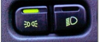
LED indicators
Each of the indicators has its own meaning and a symbolic, intuitive picture.
When the indicator lights up, there is a malfunction in the following vehicle functions:
- Oil level.
- Washer fluid.
- Coolant.
- Doors.
- Headlights.
- Seat belts.
Data-lazy-type=”image” data-src=”https://vazremont.com/wp-content/uploads/2017/08/foto-3-3.jpg” alt=”LED indication bsk” width=” 533″ height=”330″ class=”lazy lazy-hidden aligncenter size-full wp-image-3746″ srcset=”” data-srcset=”https://vazremont.com/wp-content/uploads/2017/08 /foto-3-3..jpg 300w" sizes="(max-width: 533px) 100vw, 533px">
Diagram VAZ 2112 injector 16 valves for Euro-2
1 — spark plugs; 2 — injectors; 3 — ignition module; 4 - ECU VAZ 2112; 5; main relay; 6 - fuse connected to the main relay; 7 — electric fan relay; 8 - fuse connected to the electric fan of the cooling structure; 9 — electric fuel pump relay; 10 - fuses, connected to the electric fuel pump relay; 11 — mass flow and air temperature sensor; 12 — TPS; 13 — DTOZH; 14 — electromagnetic throttle for purge of the adsorber; 15 — lambda probe; 16 - DD; 17 — DPKV; 18 — empty speed regulator; 19 — VAZ 2112 immobilizer computer; 20 — immobilizer status indicator; 21 — phase sensor; 22 — car speed meter; 23 — gasoline pump module with fuel level meter; 24 — oil pressure control sensor; 25 - coolant heat indicator meter; A - terminal connected to the ABS cabin group harness; B - diagnostic connector; B - terminal block connected to the air conditioner wiring harness; G - to the plus terminal of the battery; D - to the terminal block of the side door wiring harness; E - terminal block connected to the instrument panel wiring harness; G1, G2 - ground points; I - the order of conditional numbering of the terminals in the wiring block of the immobilizer computer; II - the order of conditional numbering of terminals in the diagnostic connector.
Scheme VAZ 2112 injector 16 valves for Euro-2 with controller M7.9.7
Basic and additional functions
On domestic VAZ 2110 cars, the on-board computer allows you to determine the air temperature outside, the speed of the car, the volume of gasoline in the tank and its average consumption. In addition, thanks to the BC, the driver will be able to find out how far the fuel in the tank will last. Depending on the model of the VAZ on-board computer, the device can show the operating parameters of the power unit and the voltage level in the car’s electrical circuit.
The main function performed by the State on-board computer is to identify combinations of errors in the components and systems of the vehicle, while connecting additional equipment is not necessary. In accordance with the instructions for the device, when the Check indicator appears on the BC screen or dashboard, you need to perform diagnostics of all systems. The received error codes are decrypted in accordance with the technical documentation; information on decoding the codes is also provided in this article
Another important function of the BC is the drying of spark plugs, which greatly simplifies engine starting, especially at low temperatures.
Message from BC about the need to replace the engine fluid
Depending on the VAZ 2110 computer model, the device can be additionally equipped with a tachometer, clock, voltmeter and even a calendar. IN practice, most BCs have volatile memory, as a result of which, when the battery is disconnected from the network, all error information will be saved. You can find many different BC models on sale, the most common of which are Gamma, Omega, Multitronics, and State 110. The latter option is optimally suited for the VAZ 2110, since models for cars are available with both an old and an improved dashboard.
The main functions of this bookmaker:
- the device provides the driver with data on fuel consumption, antifreeze temperature in the system, as well as mileage traveled;
- determining the distance for which the gasoline in the tank will last;
- providing information on car maintenance;
- demonstration of combinations of errors in engine operation;
- the ability to update the platform via the Network;
- another function is the presence of a plasmar necessary for warming up the spark plugs;
- there is a Fast and Furious option - its purpose is to reset the memory to standard settings;
- The Tropic function allows you to activate the fan when a certain engine temperature is reached.
It should be noted that these are not all the functions that a device for the domestic “ten” may have. On sale today you can find many different models of computers, the functionality of which can be expanded in accordance with the installed software. So, in general, the possibilities of a bookmaker depend on the model and, accordingly, on the financial capabilities of the buyer.
BC Gamma for “ten”
If you decide to purchase an on-board computer for a VAZ 2110, then it will be useful for you to find out what types can be found on sale:
- Universal BCs - such devices are designed for installation on any car; as a rule, they are used as an alternative to a rear view mirror. In some cases, universal devices can be installed on glass.
- Individual-type devices that are aimed at several car models at once. For example, domestic “eights”, “nines” and “tens” are one group, characterized by the presence of an old dashboard in the cabin.
Diagram VAZ 2112 injector 16 valves for Euro-3
| 1 — spark plugs; 2 — injectors; 3 — ignition module; 4 — VAZ 2112 computer; 5 — main switch; 6 - fuse connected to the main relay; 7 — relay of the electric fan of the cooling system; 8 - fuse connected to the electric fan of the cooling structure; 9 — electric gasoline pump relay; 10 - fuse connected to the relay with an electric gasoline pump; 11 — air mass flow and heat meter; 12 — rough road meter; 13 — TPS; 14 — DTOZH; 15 — idle control; 16 — control lambda probe; 17 - diagnostic lambda probe; 18 — electromagnetic throttle for purge of the adsorber; 19 — DD VAZ 2112; 20 — DPKV; 21 — immobilizer computer; 22 — immobilizer status indicator; 23 - DPRV; 24 — car speed meter; 25 — electric gasoline pump module with gasoline level meters; 26 — oil pressure warning light sensor; 27 — antifreeze heat indicator meter; A - terminal block connected to the ABS cabin group; B — diagnostic block; B - connector connected to the air conditioner wiring harness; G- to the “+” terminal of the electricity storage device; D — to the side door wiring harness connector; E - connector attached to the instrument panel wiring harness; G1, G2 - minus points; I - method of numbering contacts in the ECU wire connector by the immobilizer; II - method of conditional numbering of contacts in the diagnostic connector |
Diagram VAZ 2112 injector 16 valves for Euro-3 with controller M7.9.7
Kinds
Today you can find contact and contactless immobilizers, the latter of which are more in demand. The first ones are controlled using a key, and for the second ones a key fob or card is provided. They are combined with other anti-theft systems.
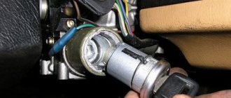
Key master
On the VAZ 2110, the immobilizer is found only on models with injection engines. When leaving the production line, the car's protective functions are not activated. A special set of keys is provided for this. One of them is red. This is the master key that activates the protection. The other two, which are black, are used by the car owner.
“Training”, that is, activation, is usually performed at a car dealership before preparing the car for sale. Although some clients are easily able to perform the procedure on their own.
The VAZ 2110 was the first to be equipped with APS-4 systems, but after some time improved APS-6 models appeared. The reading part is installed in the steering column, and the code is installed in the ignition key. APS-6 additionally serves to control fog lights and electric windows.
APS-6 module board
Sometimes an updated immobilizer comes in an old housing, which, apparently, was in abundance at production. If this is so, then there is a number 4 on the case, and the inscription APS 6 is printed on the board. Microcircuits may differ from each other due to different periods of their production.
Connection diagrams for VAZ 2112
Rear window wiper and washer connection diagram
- 1 - electric washer motor
- 2 — block of relays and fuses
- 3 - ignition switch
- 4 - rear window wiper and washer switch
- 5 — motor with rear window wiper gearbox
- K6 - additional relyushka
- A - to sources of electricity
- B - method of conventional numbering of connectors in the terminal block of a motor with a gearbox
For the rear window wiper of a VAZ 2112, in a continuous manner, with a load of the motor with a gearbox with a force of 1 Nm, a supply voltage of 13.5 V and an ambient temperature of (25±10) °C, the number of double strokes of the output shaft of the gearmotor must be from 20-30 min- 1, and the consumed current is no more than 3 A. In intermittent order under the same conditions, the number of double movements of the output shaft of the motor with gearbox must be from 15 to 18 min 1 and the current used is also no more than 3 A. In this case, the initial 3 - 4 Swings after connection must be performed in a continuous manner.
Electrical diagram for connecting electronic ignition
| 1 - source of electricity; 2 — ignition switch; 3 — ignition switch; 4 — spark plugs; 5 — ignition module; 6 - ECU; 7 - DPKV; 8 — toothed disk; A - matching device |
The ignition structure uses a spark distribution method called the “idle spark” method. The engine cylinders are combined into pairs 1-4 and 2-3 and spark formation occurs in 2 cylinders at once: in the pot in which the compression cycle ends (working spark), and in the cylinder where the exhaust cycle occurs (idle spark). With a constant direction of current in the windings of the ignition coils, the spark formation current for one spark plug always passes from the central electrode to the side electrode, and for the second - from the side to the central one.
Electrical diagram for connecting the inflatable cushion VAZ 2112
| 1 — connector connected to the airbag module; 2 - diode; 3 - fuse 8 A; 4 - terminal block connected to a connector disconnected from connector 5; 5 — instrument panel harness connector, connected to the ignition switch; 6 — signal connection switch; 7 - connector connected to the terminal block disconnected from block 8; 8 — instrument panel harness connector, connected to the fuse and relay block; 9 - connector connected to the terminal block disconnected from connector 10; 10 - instrument panel harness connector, attached to the front wiring harness |
Attention ! Removal and installation of a steering wheel with an airbag must be performed without the use of electric tools. Do not disassemble or repair the computer, airbag module and steering wheel contact coil. After turning off the battery, you must wait at least 5 minutes before disassembling.
Circuit breakers
Now let's see which fuses are responsible for what in the same mounting block. I will also give the main reasons for troubleshooting.
F1 (5 A) - license plate lighting lamps, dashboard lighting, side lights on the panel, trunk lamp, left side lights . If any of the listed lamps do not work, check this fuse, as well as the lamps themselves and their contacts. If everything is in order, check the headlight switch button.
F2 (7.5 A) - low beam in the left headlight . If both low beam headlights do not work, also check relay K4 and the lamps themselves. It could also be the light switch and its contacts.
F3 (10 A) - high beam in the left headlight . If both high beam headlights do not work, check the K5 relay, the lamps themselves and the high beam switch knob.
F4 (10 A) - front fog lamp on the right side . If both fog lights do not work, check relay 9 and the headlight bulbs themselves, as well as the switch and its contacts.
F5 (30 A) - window lift motors . If the power windows do not work, check this fuse and relay 5. In winter, check if the windows are frozen, warm them up and clear them of ice if necessary. It could also be the window lift motor, its mechanism and gears; in order to get to it, you need to remove the trim of the desired door.
F6 (15 A) - portable lamp fuse.
VAZ 2112 wiring diagram
Alternator wiring diagram for VAZ 2112
| Position number on the diagram | Explanation of the position on the diagram |
| 1 | current storage |
| 2 | generator VAZ 2112 brand 94.3701 alternating current, three-phase, with built-in rectifier unit and electronic voltage regulator, right rotation (drive side). |
| 3 | Relay and fuse block |
| 4 | ignition switch |
| 5 | battery charging warning light located on the instrument panel |
Some machines were equipped with AAK-5102 generators made in Slovenia. In terms of its characteristics and connection dimensions, it is identical to the generator 94.3701.
Starter wiring diagram
- accumulator battery
- magneto
- starter VAZ 2112 model 57.3708
- ignition switch
Wiring diagram for headlights and fog lights VAZ 2112
The low and high beam headlights are connected using the K4 and K5 relays located in the relay and fuse box.
Wiring diagram for fog lights VAZ 2112
On the VAZ 2112 hatchback, in a variant modification, fog lamps are mounted in the front bumpers. The diagram of which is presented below.
| 1 — fog lamps; 2 — relay for connecting fog lamps brand 113.3747; 3 — connecting block of VAZ 2112 relays and fuses; 4 — size switch; 5 — fog light connector; A - to the source of electricity; B - to the instrument light switch |
Electrical wiring diagram for outdoor lighting
Wiring diagram for hatchback turn signals and hazard lights
Injection "ten"
In addition to the wiring that is provided for the VAZ 2110 - carburetor, "ten" - injector, it is also equipped with a number of fuses that protect almost all of it from the possibility of short circuiting.
Structurally, fuses are not provided only for the electrical supply via a relay wire from the battery, in the car starting and ignition circuit, as well as for the wire going to the generator.
Electrical circuit of an injection car
In addition, the injector (as opposed to the carburetor) is a more complex system, and in order to repair it yourself, you need to understand it well. The controller in this wiring system “reads” the operation of all systems, thereby determining and setting many indicators - calculation of the fuel mixture, etc.
Electrical control circuit for the VAZ 2112 engine
| Position number on the diagram | Explanation of the position on the diagram |
| 1 | sprayers |
| 2 | spark plugs |
| 3 | ignition module VAZ 2112 |
| 4 | diagnostic connector |
| 5 | electronic engine control unit VAZ 2112 |
| 6 | terminal block connected to the instrument panel wiring harness |
| 7 | main relyushka |
| 8 | fuse combined with the main relay |
| 9 | electric fan relay |
| 10 | fuse located with the electric fan relay |
| 11 | electric fuel pump relay |
| 12 | fuse located with the fuel pump relay |
| 13 | Mass air flow sensor |
| 14 | TPDZ |
| 15 | DTOZH |
| 16 | idle speed regulator |
| 17 | oxygen sensor |
| 18 | DD |
| 19 | DPKV |
| 20 | electromagnetic throttle for adsorber purge |
| 21 | DPRV |
| 22 | APS control unit |
| 23 | APS status indicator |
| 24 | car speed meter |
| 25 | gasoline pump with fuel level sensor |
| 26 | oil pressure warning light sensor |
| 27 | Coolant heat indicator sensor |
| 28 | oil level meter |
| A | terminal block connected to the ABS cabin group harness |
| IN | connector that connects to the air conditioner wiring harness |
| WITH | connector that connects to the electric fan wiring harness |
| D | wires connected to the ignition switch (light bulb) |
| E | terminal block connected to the blue-white wires disconnected from the ignition switch |
| F | to the plus terminal of the current accumulator |
| G1, G2 | mass points |
Along with the letter designation of the wire colors in this diagram, the designation of the number of the circuit element to which this wire is connected is used. For example -4-. The symbol -S7- or -SF- means that the core is connected to the circuit element numbered 7 or indicated by the letter F through a connection point not shown in the diagram. In some cases, in addition to the designation, the element number is given through an oblique fraction and the connector number, for example -5/15-.
Pinout of the dashboard VAZ2108, 2109, 21099
Connection diagram of the instrument cluster before 1996.
1 – relay-interrupter for the parking brake warning lamp; 2 – tachometer with voltage stabilizer; 3 – instrument cluster lighting lamp; 4 – temperature indicator; 5 – BSK control unit; 6 – fuel level indicator; 7 – resistor 50 Ohm, 5 W; 8 – control lamp “CHECK ENGINE” for the toxicity reduction system; 9 – control lamp for high beam headlights; 10 – side light indicator lamp; 11 – backup warning lamp; 12 – warning lamp for unfastened seat belts; 13 – control lamp for left direction indicators; 14 – resistor 470 Ohm, 0.25 W; 15 – electronic voltmeter; 16 – control lamp for right direction indicators; 17 – warning lamp for emergency oil pressure; 18 – fuel reserve warning lamp; 19 – control lamp for the carburetor air damper; 20 – indicator lamp “CHECK ENGINE” for the fuel injection system; 21 – parking brake warning lamp.
Books and diagrams for repairing VAZ 2112
Here you can download the following books and diagrams for the repair and operation of VAZ 2112 .
| Order number | Name of manual or catalog | The year of publishing | Col. p. | Size | Format |
| 1 | Catalog of parts VAZ 2112, 2111, 2110 | — | 406 | 7.57 MB | |
| 2 | Operating manual for VAZ 2112, 2111, 2110 | 2008 | 92 | 1.56 MB | |
| 3 | Repair of VAZ 2101, 21011, 2103, 2105, 2106, 21073, 2121, 21213, 21214, 21214-10, 2123, 2130, 2108, 21081, 21083, 2110, 2111, 2112 engines | 2002 | 83 | 2.65 MB |
Wiring test for non-working brake lights (ground test)
Let's look at the basic diagram: the brake lights and the reversing lamps have a common ground pin. If contact with this pin is broken, the reverse lamps will not turn on. Well, brake lights too.
Connector for connecting “internal” lights. On the left side there is a connector through which the wiring goes to the fifth door. The connector has black and red wires. Check the voltages on them. Most often the ground on the black wire does not ring. But maybe the connector itself needs to be cleaned.
- Disconnect the connector with two wires from the limit switch;
- Using 17mm wrenches, loosen the two nuts: holding the lower nut, rotate the upper one;
- The end switch is removed as an assembly and checked with an ohmmeter.
By the way, one of the connector terminals receives a voltage of “12 Volts”. Check it!