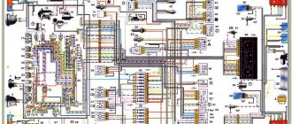
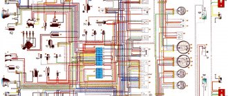
A complete collection of electrical diagrams of the Niva VAZ-2123 car of various modifications, including relay and fuse blocks.
It is possible to download free high-quality diagrams in PDF format (high resolution) from the link at the end of the article. The VAZ-2123 SUV was produced in small series at AvtoVAZ OJSC from 1998 to 2002 as an improved Niva 2121. Then GM-AvtoVAZ began producing a new car called Chevrolet Niva. In addition to the basic five-door station wagon body, there were modifications with a pickup body (VAZ-2323) and a van (VAZ-2723). The injection engine was a further development of the VAZ-21214 engine, with a volume of 1.7 liters and a power of 79.6 horsepower.
Electrical wiring components
The standard Niva Chevrolet wiring diagram is divided into several sections for better maintainability and ease of maintenance.
- Front part - a set of cables connects all equipment located in the engine compartment of the car.
- The interior part - the unit is additionally divided into independent zones, which allows you to power different groups of equipment without the risk of damaging or overloading the main elements.
- Instrument panel compartment - a bundle of cables combines the lines from all gauges, sensors and indicators.
- The stern assembly - the bundle is responsible for voltage and control of equipment located on the rear side of the vehicle.
What is a relay
A relay is called an electromagnetic switch, which is designed for switching during abrupt changes in the input value (current, voltage) in electrical circuits. In simple terms, it is a device that turns on when a voltage signal is applied to it, and turns off when the voltage disappears. The current that switches the device is very low, and to start the fuel pump a large current is required. Therefore, it is also called a kind of amplifier.
What does it consist of?
There are different numbers of relays, but almost all of them perform similar functions. This device consists of a contact group, which we can see by removing it from the block. Inside it there is a coil with a certain number of turns of copper wire, a return spring and an armature. All this is assembled in a certain sequence and located on the board. A photo of the contact group and the shape of the relay can be seen below, or you can enter it in a search engine and see all the types and types. We are interested in the Chevrolet Niva fuel pump relay, which looks like this.
Relay operating principle. The fuel pump relay is used only in engines with injection type. Carburetor engines use a mechanical fuel pump. The Niva (injection) car uses a 12V electric fuel pump. The electrical circuit of its operation includes power wires, a fuse, a relay, as well as fuel reading sensors in the tank. Thus, when you turn the car key, power is automatically supplied to the relay. It, in turn, operates instantly and closes the contacts that power the pump. This is how the fuel pump turns on briefly, as a result of which, when we sit behind the wheel and turn the key, we hear its buzzing, indicating its operation.
Location in Niva
On the right side under the glove compartment there is a cover, and under it there is part of the electronics of the Niva car, the second part is under the dashboard on the driver’s side. Under this cover you can see the location of four relays. The device that is responsible for turning on the fuel pump and its operation is located under the third number. Next to it is a 15A fuse, which is designed to protect the circuit and electrical components of the fuel pump.
location of the relay box in the car
About the main elements of an electrical circuit
The vehicle's electrical circuit includes the following components:
- Sources of electrical energy.
- Devices responsible for its consumption.
The main location of the block is to the left of the steering column. The device is closed from below with a special lid. You only need to unscrew two screws to get to the internal contents. After this, squeeze out the upper edge of the lid, gradually freeing this part from all fasteners. The entire connection diagram for the VAZ 2123 speed sensor and other devices becomes available.
A block will appear, which is held on a special bracket. Depending on the configuration and year of manufacture, the circuit itself varies, as does the total number of fuses.
Possible malfunctions in the fuel pump power supply system
Typically, the reasons for contacting a service station are breakdowns.
- Fuel pump relay or fuse has blown.
- Breakdown or short circuit in the device wiring.
- In rare cases, users experience failure of the pump motor itself.
Fuel pump relay does not work
If the toggle switch does not turn on, the problem should be looked for in two parts.
- The switch itself has burned out and needs to be replaced.
- The signal supply system to the device does not work. The ECU should be diagnosed.
Niva Chevrolet fuel pump fuse blows
If the fuse link burns out constantly, the problem should be looked for throughout the entire circuit. The fuse blows due to a short circuit in the wiring to ground or on-board circuit, motor failure or power surges.
Replacing the fuel pump fuse
You must remove the glove box and get to the auxiliary mounting block. The fusible element is directly removed from the socket using special pliers. The structure is assembled in the reverse order.
Replacing the fuel pump relay Niva Chevrolet
It is enough to unscrew its fastening from the mounting plate and disconnect the contact group. You can see how this is done in the video.
Pinout of Niva Chevrolet connectors responsible for the front part of the wiring
- 1/6 – front right/left headlight block;
- 2 – joint assembly of the machine starter;
- 3 – voltage supply for traction starter;
- 4 – battery connection terminals;
- 5 – generator module for powering the electrical circuit;
- 7/15 – units for combining head optics fog lights;
- 8 – contact group for the drive of the electric motor for the front windshield washer;
- 9 – input of a temperature sensor that measures indicators outside the vehicle;
- 10 – contact plug for the engine compartment lighting lamp;
- 12 – standard sensor for measuring the remaining brake fluid level;
- 13 – plug of the standard electric motor for driving the windshield wiper;
- 14 – designation of a standard horn;
- 16/17 – plug inputs to the dashboard.
Replacing fuses
Before replacing an element, it is necessary to eliminate the cause of its failure. Do not use fuses of a different rating. The calculated current strength for each circuit can be found in the assignment table located above in the article.
The protective device may fail due to long periods of use, so if any consumer stops working, the first thing to check is its fuse.
They are held in their nests by sliding contacts. In order to remove the element, simply pull it out of the socket. To make this more convenient, modern mounting blocks are equipped with plastic tweezers.
A faulty fuse can be determined by visual inspection or using an ohmmeter. Since the housings are made of transparent plastic, the integrity of the conductor is easy to determine with the naked eye. In addition, conductor burnout is accompanied by an increase in temperature. Traces of heat exposure remain on the plastic case. Having selected an element suitable for its nominal value, it is inserted into the socket in place of the failed one.
In no case should you use bugs instead of a fuse, as they may not burn out when the current increases, which will lead to overheating and fire of the wiring.
If a fuse burns out on the road, you can replace it with an identical one that protects the circuit of the consumer that is not currently in use.
More information about Chevrolet Niva electronics can be found here.
Chevrolet Niva is a Russian-assembled compact crossover. Produced in 2002, 2003, 2004, 2005, 2006, 2007, 2008. In 2009, the car received a restyling. The updated version was produced in 2010, 2011, 2012, 2013, 2014, 2015, 2016, 2022 and 2018. We will look at a block with Chevrolet Niva fuses and relays with a full description of the presented circuits. Let's show you where the cigarette lighter fuse is located.
p, blockquote 1,0,0,0,0 —>
p, blockquote 2,0,0,0,0 —>
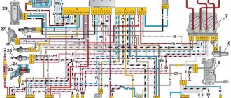
Chevrolet Niva wiring diagram, part of the ECM
- 1 – spark plug pins;
- 2 – contact group of injector drivers;
- 3 – ignition unit;
- 4 – control controller;
- 5 – main protective relay of the internal combustion engine;
- 6 – area for location of fuse links;
- 7 – main relay fuse;
- 8/9 – protective circuits of the right and left head fans of the radiator;
- 10 – protective element for the control fuse of the main fuel pump;
- 11 – controller circuit fuse;
- 12 – secondary protective element of the main radiator fan on the right side;
- 13 – auxiliary fuse of the above circuit;
- 14 – fusible link of the fuel pump control circuit;
- 15 – fan of the main radiator, located on the left side;
- 16 – standard oxygen concentration sensor in the intake manifold;
- 17 – drain output of the detonation channel meter;
- 18 – DPKV output;
- 19 – control by the adsorber purge valve;
- 20 – output of the mass air flow sensor group;
- 21 – idle speed control drive;
- 22/23 – activation of the left/right fan motor of the main engine cooling system;
- 24 – auxiliary resistor;
- 25 – control of the TPS device;
- 26 – output from antifreeze temperature sensor;
- 27 – status indicator of the above-described sensor;
- 28 – standard module for measuring lubricant pressure in the crankcase compartment of the power plant;
- A/B – battery terminal blocks;
- C – “mother” input for connecting to the dashboard;
- G1/G2 – grounding outputs of the wiring section.
Also interesting: Low pressure UAZ tires in Nizhnekamsk

