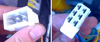
The fuel pump relay is located under the dashboard. On the passenger side, a side panel is opened that covers the beard on which the radio, on-board vehicle, and heater controls are mounted. We see a strip with three relays and fuses.
The pump relay is the lowest.
Its fuse is also at the very bottom. When you turn the key, the relay turns on for 5 seconds in order to pump up pressure in the system and turns off. After the engine starts, control of the pump passes to the computer. The mass of the pump (and fuel level sensor) is attached to the stud securing the handbrake to the body under the carpet. To get to it you need to remove the vestibule between the passenger and driver seats. There are 3 wires coming to the fuel pump: the first is +, the second is minus, the third is the fuel level sensor.
Where is
If we describe them from top to bottom, we get the following:
1. The fuse that controls the fuel pump. Its current strength is 15 amperes.
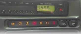
Lit
A fuse is a small element whose task in the design of electrical circuits is to melt in the event of an overload. The device melts and the current-carrying circuit opens.
Using the example of a solution from the popular VAZ Priora model, we can superficially examine the design and operating principle of the fuse. The device is small, the outer casing is made of plexiglass.
There is a conductive element inside. Such an element is based on several plates, which are made of different materials. Between these plates there is a special low-melting material. Electricity passes through this material, which allows the fuse to be an integral part of the electrical power circuit of the fuel pump. Fuses have a special marking in the form of the letter F. This designation indicates that the fuse element belongs to a circuit whose power is not large. To calculate the current that certain devices are designed for, you need to divide the power by 220. The result will be a figure in amperes.
If the fuse is blown, then such a malfunction is often caused by the following reasons:
— short circuit in the electrical circuit;
— failure of the fuel pump relay;
- low quality of the fuse itself;
In other words, more often the fuel pump fuse blows due to faults in the electrical circuits or as a result of failure of the components of the pump power circuit. Note that situations also arise when the fuel pump fuse burns on its own, but this phenomenon occurs much less frequently with high-quality elements.
How to identify a malfunction
The fuel pump relay turns on the fuel pump and delivers fuel to the injectors. The safety relay is activated when the engine is not running and the ignition is on (the control unit does not receive speed signals). This relay is switched off in the control unit via a safety switch and interrupts the power supply to the pump. For example, in the event of an accident, gasoline cannot flow into the engine. Checking the fuel pump is a job most likely reserved for service centers. In this regard, to find errors, we will limit ourselves to the following points:
— disconnect the fuel supply line at the distributor, while preparing a rag for spilled gasoline;
— even when the engine is turned off, a certain amount of gasoline may come out, since the system is under pressure;
— turn on the ignition for a short time without turning on the starter;
— if the pump does not start working, check the fuse or safety relay again;
— if fuel does not flow, check the pump relay;
— if the relays are working properly, the fuel pump should start working;
- otherwise, remove the cover under the rear seat and carefully tap the pump housing with a small hammer - sometimes it helps;
— check the correct connection of the wires to the fuel pump;
- if the pump does not work, check the voltage using a diode bridge (a conventional test lamp can damage the control unit). Don't forget to turn on the ignition first;
- if the voltage is normal, it means the pump is damaged or there is an open circuit. The pump should be replaced with a new one.
Pinout of fuel pump VAZ 2107
1 – radiator fan drive motor; 2 – mounting block block; 3 — idle speed sensor; 4 – engine ECU; 5 – potentiometer; 6 – set of spark plugs; 7 – ignition control unit; 8 – electronic crankshaft position sensor; 9 – electric fuel pump; 10 – indicator of the number of revolutions; 11 – lamp for monitoring the health of electronic systems and the brake system; 12 – ignition system control relay; 13 – speedometer sensor; 14 – special factory connector for reading errors using the BC; 15 – injector harness; 16 – adsorber solenoid valve; 17, 18, 19,20 – fuse box for repairing the mounting block that protects the injection system circuits; 21 – electronic fuel pump control relay; 22 – electronic relay for controlling the exhaust manifold heating system; 23 – exhaust manifold heating system; 24 – fuse protecting the heater circuit; 25 – electronic air sensor; 26 – coolant temperature control sensor; 27 – electronic air damper sensor; 28 – air temperature sensor; 29 – pressure control sensor and low oil pressure lamp.
You can check the fuel pump on a VAZ 2107 simply by checking the voltage at its connection block with a tester. The presence of voltage will indicate a malfunction of the electric motor. Instead of a tester (multimeter), you can use a test lamp to diagnose a malfunction.
In the absence of one, this can be done by disconnecting the connection block for the fuel pump and fuel level control and applying voltage with wires from the battery to the place where the gray wire is connected +12 and to the place where the black wire is connected - minus. A humming pump will indicate a faulty fuse, power circuit or ECU.
Description of the work
The location of the VAZ 2110 injector fuel pump is in the gas tank located under the bottom of the car, in the area of the rear seat. It is accessible from the cabin, so no inspection holes or other additional devices are required. Only tools needed:
- open-end wrench 13 and 17 mm;
- Phillips screwdriver;
- 7 mm tubular socket wrench.
Instead of a long 7 mm tubular wrench, you can use a small open-end wrench, but this will be inconvenient and take more time. Before starting repairs, you should completely remove and pull out the rear seat to gain access to the gas tank. Two more preliminary operations that are done in the engine compartment.
- Loosen the nut securing it to the negative terminal of the battery, remove the clamp along with the wire.
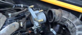
- Relieve pressure from the fuel line. At the end of the ramp, near the outer nozzles, there is a bleed valve with a rubber cap on it. Having removed it and substituted a plastic cup, you need to press the valve stem. Fuel will leak out from there and the pressure in the system will drop.
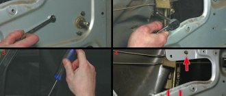
Under the bottom of the rear seat there is a square hatch that provides access to the gas tank; it will need to be removed. The subsequent disassembly diagram looks like this.
- Using a Phillips screwdriver, unscrew the 2 screws securing the hatch cover, remove it and put it aside.
- Disconnect the fuel pump electric drive connector and move it out of the way.
- Using an open-end wrench, loosen and unscrew the 2 nuts that secure the fuel line pipes to the fuel pump fittings.
- Pull the tubes out of their sockets. The round rubber rings attached to their ends must be removed and replaced with new ones, since they are designed for one-time use.
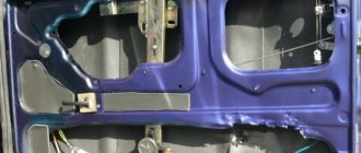
- Using a long tubular wrench, unscrew the 8 nuts that hold the flat flange that presses the VAZ 2110 fuel pump to the bottom surface. Remove the flange from the studs.
- There is a rubber gasket on the mounting studs under the clamping part of the body. The latter must be removed from the studs, otherwise it will not make it possible to pull out the fuel supply device. Then carefully remove the fuel pump from the tank cavity along with the float. If the rubber gasket is worn out, then it is better to replace it too.
When removing the unit, gasoline will flow out of it, so you should place a rag underneath and quickly move the fuel pump out, placing it above a wide pan. The mesh is located at the end of the suction tube and is secured with a plastic ring. You can remove it manually.
If the ring is strongly stuck to the tube, it is recommended to pry it off, for example, with a flat screwdriver. Next, a new mesh is placed and fixed by pressing the hand all the way. Now you can reassemble, which is done in reverse order. There is an arrow stamped on the top of the unit; it should point to the rear of the car.
We recommend tightening all connections with little force. To avoid distortion when tightening the 8 nuts of the clamping flange, a star tightening pattern is used.
If it is necessary to replace the fuel pump on a VAZ tenth model or repair it, then the system is disassembled as described. When replacing, you need to remove the float and level sensor from the unit and move them to the new pump. The entire procedure, if performed in conjunction with replacing other consumables, will take you no more than half an hour.
Popular breakdowns
Problems with the fuel pump can occur for several reasons. Therefore, your first priority is to determine the source of the problem. These may be:
- Fuel pump fuse;
- Fuel pump relay;
- Pump weight;
- Motor;
- Contacts;
- The pump itself.
If one of these elements fails, it can stop the normal functionality of the entire module.
Let us consider the situations with each of the specified elements of the fuel module in more detail.
The fuel pump relay does not turn on.
If the fuel pump does not work, then first of all you need to check the attraction of the main relay and the fuel pump relay. If the main relay does not click, then it is necessary to check its switching circuit and its serviceability. How to do this is described in the article the main relay does not turn on,
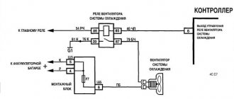
In the case when the main relay turns on, but the fuel pump relay does not, it is necessary to check the power at pins 85 and 86. When using a test lamp, its current consumption should not exceed 0.25A, otherwise damage to the controller may occur. If the control lamp does not light up on any terminal, then the relay is not receiving power. This may be caused by a blown fuse or a broken power cord.
In the case when the lamp burns brightly on one terminal, and at half-glow on the second, and the relay may be activated, you should remove the relay from the socket and connect terminals 85 and 86 with a test lamp. When the ignition is turned on, the control lamp should light up and go out after approximately 20 - 30 seconds. If the lamp lights up and there is poor contact in the connection between the block and the fuel pump relay. If the lamp does not light up, there may be a break in the wire connecting the relay to the controller or the controller itself may be faulty.
Causes: fuse, relay, connector
The pump power circuit includes many elements: closed relay contacts 5, fuse 3 (15 A), “+” wire, “pump-to-ground” wire. The most “difficult” defect is a short circuit of the “+” wire to ground. By the way, the cord itself is laid on metal, so such a defect cannot be ruled out.
Mounting block for dashboard
Both the relay and the fuse are located in a block located under the dashboard on the right. A fuse can blow in two cases:
- The “+” cord makes contact with ground;
- The motor resistance decreases due to overheating.
The first defect may be “floating”, and then it will be difficult to identify. But before calling an electrician, try checking everything else:
- Relay 5 should click twice: when the ignition is turned on and after 1.5 s. If this does not happen, replace the relay;
- Check fuse 3. If it is blown, you need to look for the cause.
Consider the situation: the relay is working, but the fuse is blown. Then we do this: disconnect the pump connector, install a new fuse and measure the voltage at the terminals. Details are below.
Connectors under the hatch, disconnecting them
You need to remove the hatch under the rear seat: two screws are unscrewed with a Phillips screwdriver. Next you need to disconnect the connector on the module, and then move on to the block under the dashboard.
First, turn off the fuel pump!
Replace the fuse. Let's move on to the fuel pump: connect the probe (zero cord) to any of the mounting studs. Voltage should appear on the “gray” wire when the ignition is turned on. And also check the potential difference between the “gray” and “black” wires - it should be equal to 12 volts, and also at the moment the ignition is turned on. Wiring:
- The two outer cords are the FLS sensor;
- “Black” – minus power supply;
- "Grey" is a plus.
Missing mass or plus?
Design and principle of operation of the injector
The 4's fuel pump runs on electricity. Therefore, if there is no power to the VAZ 2114 fuel pump, you need to determine where exactly the circuit is broken. After all, both mass and plus may be missing.
VAZ 2114 fuel pump power supply circuit
Car enthusiasts sometimes have a question about how to check the power supply to the VAZ 2114 fuel pump. You need to start with something simple. To do this, you need to turn the ignition key and listen for a characteristic click. It is familiar to every driver. The fuel pump always starts with this sound.
If there is no sound, you need to check the relay and fuse. They are located on the passenger side, under the side panel. To get to the electrical components, remove the plastic trim on the passenger side.
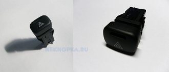
To check the fuse, you need to take a known good fuse element and put it in its place. If everything worked, then that was the reason. A faulty relay can be indicated by the absence of a click when turning the key. These electrical elements sometimes exhibit external damage that is visible to the naked eye. But, if replacing the relay did not help, then you should look for the reason further.
To understand why there is no power, you need to do the following:
- Raise the back seat and find the gas filler door. It is held on by self-tapping screws;
- After removing the hatch, three terminals will be visible, two of which are positive and one is negative;
- We check the power by connecting the ends of both wires alternately to plus and minus. If the light is on, it means there is power. When the lamp is not lit, it is absent.
If the lamp is on and the pump is not functioning, you need to check the voltage. To start the VAZ 2114 gasoline pump, a voltage of 10 volts or more is required. Measurements are carried out by the tester in voltmeter mode.
Low voltage indicates:
- Low battery. Therefore, you need to check its charge level;
- Problems with the generator. But they are usually accompanied by a number of symptoms that should have been noticed earlier;
- Oxidation of connectors. This can be noticed upon visual inspection. Cleaning will easily solve this problem;
- Broken wiring. You will have to call it with a tester to find the location of the damage. If it is difficult to find a break on your own, you should contact a car service.
If the fuse and relay are working, the voltage is normal and there are no breaks, you should check the fuel pump. This part cannot be repaired. If it breaks, it is replaced. It also cannot be ruled out that the pump is blocked by a car alarm or similar additional equipment, if installed. It is better to entrust the inspection of such devices to an auto electrician.
Signs of fuel pump malfunctions
The main symptoms of fuel pump failure, as well as malfunctions in its operation, are:
- the car starts with difficulty, the engine runs unstable, there are dips, jerking when pressing the gas pedal, etc.;
- the pump does not pump after turning on the ignition, does not turn the starter and does not pump the fuel pump, the engine does not start;
There have also been cases when the fuel pump stops pumping while driving. In such a situation, the engine begins to malfunction and stalls immediately after the remaining gasoline in the fuel line is used up. The problem can occur either regularly or periodically.
Where to look for the connector
It is important to know that on different cars the required socket is located in different parts of the car. Moreover, on some AvtoVAZ models it may be in a completely different place compared to another car. Let's look at several VAZ cars as an example:
- on the VAZ-2112, as well as on the 2110, as well as 2111, the socket is located to the right of the driver’s seat, immediately under the column;
- on models 2108, 2109 and 21099, the socket you need is located under the glove compartment, on a special shelf;
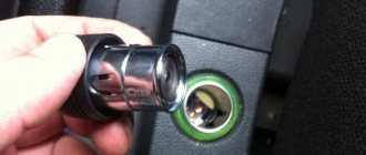
- on cars with a europanel it can be found in the center of the console, near the cigarette lighter. A special decorative cover is used to disguise it;
- on Lada Kalina cars, the connector can be found near the gear shift lever. As is the case with cars with a Europanel, it is hidden under a special cover;
- on a Priora you need to look for it right behind the glove compartment, on the wall.
Diagnostics
Pump failure can be caused by two reasons:
- Faulty fuel pump relay or blown fuse.
- There is a fault in the power circuit.
To check the electrical circuit and relay, do the following:
- Turn the key to the ignition position, but do not start the power unit. After turning the key to the ignition position, a click of the relay should be heard and then there should be a brief activation of the pump. If you do not hear a click from the relay, it means it is faulty or there is no power to it. If the relay clicks, but the pump does not work, then the problem is in the wiring that goes from the relay to the pump;
- Locate the relay box under the glove box. The block consists of three relays and three fuses for them. The fuel pump relay is located in the center. Remove the fuse, check its integrity and replace it if necessary;
- Take a multimeter and set the measurement mode to 20V. Next, touch one of the probes to the contact on the relay where the pink wire is connected. Touch ground with the other probe and turn on the ignition. The screen should display the on-board voltage from 11.5 to 12.5 V. If there is no voltage, the problem will be in the ignition switch contact group or a broken wiring. To test the relay, use a jumper to connect the terminals to which the gray and pink wires go. If the fuel pump starts working, change the relay;
- Make sure that the negative wire on the body is not oxidized. Often, interruptions in the operation of the pump are associated with a lack of mass. The ground wire is located near the handbrake mounting bolts;
- To check the pump, remove the rear seat and the fuel module cover. Disconnect the power connector on the fuel module and supply 12 V there directly from the battery. If the fuel pump works, the problem is in broken wiring; if it doesn’t work, you need to change the pump;
- Also, the pump may not produce the required pressure for the injection system to operate. It is not difficult to measure the pressure yourself, but you need to have several special devices. We recommend stopping by a service station and asking them to measure the pressure of the fuel pump. It should produce 2.8–3.2 kPa for a 1.5 engine and 3.7–3.9 kPa for a 1.6.
Ignition system and starter connection diagram
The VAZ wiring diagram includes a VAZ ignition system module, consisting of two high-voltage transformers and two electronic control units. They are in a durable plastic case, from which 4 high voltage wires are removed. They have a connection that creates a synchronous passage of a spark entering the cylinders of the power plant.
The VAZ 2114 ignition module consists of a two-spark coil and is of the block type. The ignition switch turns on a relay that sends a signal to the controller. The latter is the control element of the injection system for starting the fuel pump. It is connected to the cleaning filter with a flexible hose. After this, gasoline is supplied to the fuel rail, from which the fuel is supplied to the injectors.
The pinout of the VAZ ignition switch is in itself. It has an anti-theft device. When the lock socket illumination is on and the engine is running, the anti-theft locking device blocks the VAZ starter from re-engaging.
The starter connection diagram consists of:
- the starter itself;
- generator;
- rechargeable batteries;
- ignition switch;
- two relays.
The engine for the VAZ 2114 is also a four-stroke injector, in-line with an 8-valve unit. Its camshaft is at the top. Operates on gasoline fuel and is equipped with 4 cylinders. It is cooled with a special liquid solution. The engine compartment contains a motor located perpendicular to the direction of movement.
The VAZ wiring diagram has electronics that control the injection system. It operates at low voltage, so it can be damaged very easily by electrostatic discharge. To prevent this from happening, do not touch the circuit elements on the boards or the ECU plugs.
Fuel pump relay problem?
Topic author Sefios, 11.8.2009, 20:56
- Log in to reply to this topic
#21 6epk
- Offline
- Card
- PM
Message added 1.6.2010, 17:47
The relay, as mentioned above, is where the thick gray wire comes from. The control signal to the relay comes from the ECU and is controlled by ground. When the ignition is turned on, the fuel pump runs for a certain time to establish pressure in the fuel rail.
Check with the ignition on: 1. is there a + on the pink wire on the 30th leg of the relay 2. is there a + on the pink-black wire on the 85th leg of the relay 3. is there - on the gray-black wire on the 86th leg of the relay the first 3 seconds (control ground signal from the ECU)
good luck with the checks, I don't like the stock ECM system. in my car everything was assembled from scratch, there are only 3 relays in the car
- ∧
- Full editing
- Quick Edit
#22 Mike-ROMEO
- Offline
- Card
- PM
Message added 1.6.2010, 19:58
- ∧
- Full editing
- Quick Edit