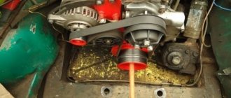
I thought about this thing last winter, when short trips around the city (home-work, home-shop, etc.) with all consumers turned on began to make themselves felt. Many people have probably heard about installing a “boost diode on the voltage regulator,” and so, after reading this article, I thought: in this situation, the voltage in the on-board network is not manually regulated, it simply becomes greater by the value by which the voltage drops when current passes through a diode. First, a little theory: when current passes through a diode, the voltage drops by an average of 0.5 volts (depending on the diode), and the standard regulator thinks that the voltage has dropped in the on-board network and makes the generator produce more voltage. Practice: we take the same circuit as for the “boost diode” and add to it a second diode and a 3-position switch, and you can use any diode, just so that it is designed for a current of at least 5A, then we assemble everything like this scheme
And voila first position 14.2 V, second position 15.4 V, third position 14.8 V
The voltage stabilizer in the on-board electrical system of a car is the most important component without any exaggeration. Not only the stability and longevity of the battery will depend on the quality of its work. At the same time, even a completely serviceable stabilization device does not always guarantee compliance with the voltage and quality of power supply of the vehicle’s electrical network. Car enthusiasts often wonder how to make the generator voltage regulator relay more reliable - contact a service station specialist, assemble or improve it yourself? There are many options.
Modern stabilizers
On modern vehicles, as a rule, self-oscillating relays are installed. They work on the principle of turning off the power to the excitation coil when the voltage reaches the upper limit of 13.5-13.8 V and connecting at the lower voltage threshold of 14.5-14.6 V.
Thus, the output voltage fluctuates constantly. Theoretically, this is not considered a disadvantage, since the voltage does not exceed acceptable limits. Still, this is not entirely safe. Surely experienced drivers know that the weak point of this type of relay is the transition moments when the rotor speed or load current changes sharply. A particularly unfavorable moment occurs with a large load current at low speeds. At these moments, voltage fluctuations often exceed the upper threshold. Due to the short duration of such surges, the battery will not fail immediately, but each time its capacity and, accordingly, resource is reduced.
This problem is solved in different ways. Sometimes car enthusiasts simply replace the self-oscillating relay with an outdated contact-vibration relay. A more optimal solution would be to replace the relay with a pulse-width stabilizer or upgrade the “native” one with the help of small additions.
SHI stabilizer
Pulse-width stabilizers are characterized by more stable operation, that is, an almost constant voltage is supplied to the vehicle network, and small deviations within the normal range are smooth. The device circuit uses the same parts as in the original, but at the same time the K561TL1 microcircuit is included. This made it possible to assemble a multivibrator and a short pulse shaper on the 1st node. The output switch control unit has also been simplified due to the use of a field-effect transistor with increased power.
Stabilizer operation cycle
When the ignition is turned on, a low logic level appears at the output of trigger DD1.1. As a result, transistor VT1 opens with the charging current of the capacitor SZ. It, in turn, begins to supply a high level to the inputs of element DD1.2, simultaneously discharging capacitor C4. When a low level appears at the output, DD1.2 opens the field-effect transistor VT3. The current from the stabilizer output flows through the excitation winding of the generator.
After the pulse stops, a high level is formed at the output of DD1.1 and transistor VT1 closes. Capacitor C4 is charged by the current passing through resistor R5 from the generator, which is controlled by transistor VT2. While the voltage on capacitor C4 drops to the lower switching limit of trigger DD1.2, it will switch. A high level will appear at its output, which will close transistor VT3. In order to protect the input circuits of the DD1 microcircuit, the voltage of capacitor C4 is limited by the diode VD4, which, when it is subsequently charged, will not lead to switching DD1.2. When a low-level pulse is again formed at the output of the generator, the process begins to repeat.
Thus, stabilization is carried out by the duration of the on state of the field-effect transistor, and the process is controlled by a measuring device, as well as a current generator. When the voltage at the generator output increases, the collector current of transistor VT2 increases. As the amperage increases, capacitor C4 begins to charge faster and the duration of the on state of transistor VT3 decreases. As a result, the current that flows through the excitation winding of the generator decreases and, of course, the output voltage of the generator decreases.
When the voltage at the output from the generator decreases, the current at the collector of transistor VT2 decreases. As a result, the charging time of capacitor C4 increases. This leads to a longer period of switching on of the transistor VT3 and the current that flows through the excitation winding of the generator increases. The generator output voltage also increases.
Specifications.
| Rated voltage, V | 28 |
| Weight, kg | 1,3 |
| Voltage reduction at the “plus” and “Sh” terminals at a load current in the “Sh” terminal circuit of 3.5 ± 0.3 A, a voltage at the positive and negative terminals of 25 ± 0.5 and an ambient temperature of (25 ± 10) ° C , IN | 2,0 |
| Load limitation current, A | 110 — 135 |
| Adjustable voltage at generator speed 3500±150 rpm, load current 60±3A with connected batteries at ambient temperature 25±10°C, V | |
| Regulator relay for temperate climates with the seasonal adjustment switch set to the “summer” position | 27,0 — 28,2 |
| Regulator relay for temperate climates with the seasonal adjustment switch set to the “winter” position | 28,7 — 30 |
| Regulator relay for tropical climates (no seasonal adjustment) | 26,3 — 27,5 |
Voltage Regulator Upgrade
This is another option to improve the quality of the relay and its resistance to transient moments. The standard relay 50.3702-01 was taken as a basis, with only one resistor and capacitor added to the circuit.
In the diagram, the modification is indicated in red and, as you can see, does not require much effort or special experience in radio electronics. When the voltage in the on-board electrical network increases, capacitor C2 begins to charge. In this case, part of the current flows through the base of transistor VT1 and is proportional in magnitude to the rate of voltage increase. This leads to the opening of transistor VT1 and the closing of transistors VT2 and VT3. In this case, the current in the excitation coil decreases, and earlier than without an additional installed circuit. This allows you to significantly reduce voltage fluctuations in the network or eliminate them altogether. The same goes for reducing voltage. In other words, the permissible voltage limits are narrowed, and the smoothness of stabilization increases.
In this diagram, you can also introduce another rational proposal. As you know, the output voltage of the generator is optimized depending on the ambient temperature and in winter it should be higher by 0.8 V, reaching somewhere around 14.6 V. According to the standard, seasonal adjustment is performed by removing or installing jumpers S1, S2 and S3. Installing jumpers eliminates resistors R1, R2 and R3 from the circuit and the output voltage increases. When the jumpers are removed, the transistors turn on again and the voltage drops. To avoid this, the mentioned transistors can be replaced with one trimmer and the output voltage can be adjusted more easily and with greater accuracy.
A generator voltage regulator relay has been created to adjust the “voltage” supplied to the on-board network and to the battery terminals in a given range of 13.8 - 14.5 V (less often up to 14.8 V). In addition, the regulator adjusts the voltage on the self-excitation winding of the generator.
About regulators
Structurally, tablets that control the voltage in the generator are capable of increasing the current to 13.6 volts. It is known that there are two schemes for connecting the regulator: old and new.
The old circuit is a more reliable option, which does not increase the voltage too much, but also does not allow it to drop to critical values. But the new one - although it is completely copied from the old one, has many shortcomings.
Chronic undercharging of the battery is precisely the drawback of the new scheme. Starting the engine becomes problematic in the cold season. Owners have to install preheaters or come up with something else.
Poor quality regulators force the battery to absorb energy only in the summer, i.e., at above-zero temperatures. In winter, especially if you make short trips by car, the battery does not have time to warm up, at least to 0, and periodically discharges.
Experienced motorists recommend driving for at least 20-30 minutes in winter to restore the battery.
So how is the problem solved? Obviously, the best option is to increase the voltage in the on-board network, but how to do this? It is necessary to make the tablet “believe” that there is supposedly low voltage in the network. Thus, we will ensure that the gene produces the missing voltage.
Low voltage in the vehicle's on-board network can be caused by the presence of a large number of consumers. For example, if you use a powerful speaker system with a subwoofer and amplifier, voltage dips are inevitable.
Instead of a diode, you can also use special regulators that produce three voltage values, depending on the air temperature: 13.2, 13.9 and 14.5 volts. There are three modes: summer, spring/autumn and winter.
We recommend viewing the table, which shows data on the normal charge of the battery and the standard operation of the generator.
| Battery charge level | Charge the battery with a charger | Generator operation |
| 12.72 volts - 100% | If the EMF is less than 12.6 V | norm - from 13.6 V - to 14.4 V |
| 12.50 volts - 75% | Uload – less than 9 V (load fork) | less than 13.6 V – undercharge (bad) |
| 12.35 volts - 50% | Electrolyte density is less than 1.25 g/cm | more than 14.4 V – overcharge. (also bad) |
| 12.10 volts - 25% |
The effectiveness of the diode, which increases the voltage in the on-board network, is beyond doubt. Almost all experienced motorists and owners of domestic models do this. After this, the car will be easy to start not only in summer, but also in winter. High current – accurate charging.
Forget about fines from cameras! An absolutely legal new product - Traffic Police Camera Jammer, hides your license plates from the cameras that are installed in all cities. More details at the link.
- Absolutely legal (Article 12.2);
- Hides from photo and video recording;
- Suitable for all cars;
- Works through the cigarette lighter connector;
- Does not cause interference to radios and cell phones.
A generator voltage regulator relay has been created to adjust the “voltage” supplied to the on-board network and to the battery terminals in a given range of 13.8 - 14.5 V (less often up to 14.8 V). In addition, the regulator adjusts the voltage on the self-excitation winding of the generator.
Purpose of the voltage regulator relay
Regardless of experience and driving style, the car owner cannot ensure the same engine speed at different times. That is, the crankshaft of the internal combustion engine, which transmits torque to the generator, rotates at different speeds. Accordingly, the generator produces different voltages, which is extremely dangerous for the battery and other consumers of the on-board network.
Therefore, replacing the alternator regulator relay should be done when the battery is undercharged or overcharged, the light is on, the headlights are flashing and other interruptions in the power supply to the on-board network.
Interconnection of car current sources
The vehicle contains at least two sources of electricity:
- battery - required at the moment of starting the internal combustion engine and the primary excitation of the generator winding; it does not create energy, but only consumes and accumulates at the time of recharging
- generator – powers the on-board network at any speed and recharges the battery only at high speeds
Both of these sources must be connected to the on-board network for the correct operation of the engine and other electricity consumers. If the generator breaks down, the battery will last for a maximum of 2 hours, and without the battery, the engine driving the generator rotor will not start.
There are exceptions - for example, due to the residual magnetization of the excitation winding, the standard GAZ-21 generator starts on its own, subject to constant operation of the machine. You can start a car “from a pusher” if it has a DC generator installed; with an AC device, such a trick is impossible.
Voltage regulator tasks
From a school physics course, every car enthusiast should remember the principle of operation of a generator:
- when the frame and the surrounding magnetic field move mutually, an electromotive force arises in it
- The stators serve as the electromagnet of DC generators, the EMF, accordingly, arises in the armature, the current is removed from the collector rings
- In the alternating current generator, the armature is magnetized, electricity appears in the stator windings
In a simplified way, we can imagine that the magnitude of the voltage output from the generator is influenced by the value of the magnetic force and the speed of rotation of the field. The main problem of DC generators - burning and sticking of brushes when removing large currents from the armature - has been solved by switching to alternating current generators. The excitation current supplied to the rotor to excite magnetic induction is an order of magnitude lower, making it much easier to remove electricity from a stationary stator.
However, instead of terminals “–” and “+” constantly located in space, car manufacturers received a constant change in plus and minus. Recharging the battery with alternating current is not possible in principle, so it is first rectified with a diode bridge.
From these nuances the tasks solved by the generator relay flow smoothly:
- adjusting the current in the excitation winding
- maintaining a range of 13.5 - 14.5 V in the on-board network and at the battery terminals
- cutting off the power to the excitation winding from the battery when the engine is turned off
Therefore, the voltage regulator is also called a charging relay, and the panel displays a warning light for the battery charging process. The design of alternating current generators includes a reverse current cut-off function by default.
Generator UAZ Patriot
The content of the article:
1. Replacing the positive wire from the generator + power calculations for UAZ Patriot
2. Repair of the voltage regulator relay for the UAZ Patriot generator
3. Installation of the voltage regulator of the UAZ Patriot generator
4. Modification of the Pramo-iskra 5122.3771-30 T generator for UAZ Patriot
Replacing the positive wire from the generator + power calculations for UAZ Patriot
Under load, I lose 0.25 volts between the B+ terminal of the generator and the battery (I think this happens to almost everyone).
In this case, there are almost no losses between the generator housing and the ground. There is only one solution - replacing the wire from the generator to the starter, where there is a connection with a wire of sufficient thickness. To do this, you need a copper wire of 0.5 meters with a cross-section of 25 square meters. mm (I set 19 sq. mm - there was no other), two terminals for studs of 6 mm and 8 mm and a plastic corrugation. Photo below, note the toy standard terminals. For reference: 1. The cross-section of the standard wire is 12 sq. mm. (diameter 4 mm). 2. Calculation of the required cross-section www.ivtechno.ru/raschyot_secheniya, that is, a standard wire can hold about 60 A without significant losses, i.e. half the generator power. 3. In case someone forgot: cross-sectional area = radius squared * 3.14
RESULT: before the installation below the imprinted man-made work of engineering, the losses were 0.25 volts, now 0.1 volts. The B+ stud on the generator gets noticeably hot, the nuts on it are tightly tightened, and it is thin (only 6 mm, and it’s steel, not copper!). I'll put an end to this and won't do anything else.
In my car, if you turn on everything possible, the current consumption from the generator is 81 amperes. The thickness of the installed wire is quite enough.
Standard wire with terminal to the generator. Notice how thin the terminal is!
Was vs became.
Terminal to starter. Was vs became.
Repair of the voltage regulator relay for the UAZ Patriot generator
Not God knows what kind of breakdown, but it will be useful for beginners. A few days ago the generator relay-regulator got tired of working. Its breakdown was worth the burnt-out low-beam lamps (that's what I've discovered so far). Obviously, the first symptom of the breakdown was the illuminated indication “ABC malfunction” and “Brake system malfunction”, and the parking sensors failed. Then I paid attention to the generator voltage (the clock under the tachometer) - 18 V was blinking. After reading the forums, I bought a three-level regulator 67.3702 - 04 from Energomash CJSC (Kaluga).
The box is simple in Russian, but you will find a lot of useful information on it.
Among the important inscriptions: modification of the regulator that you received.
How to switch the regulator.
Passport
Reverse side
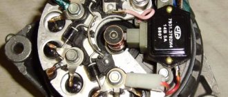
The actual product. On the right is a plug for the brushes.
Switch. The wires are normal, plus/minus for a fool, you can’t confuse them.))
The biggest problem is removing the generator. Or rather, a belt, a generator - 2 studs (bolts). If you follow the instruction manual, you must first remove the air conditioner drive belt, the power steering, and then the generator drive belt. I have almost no tools, I couldn’t remove the first belt and fell into a quiet panic. But I found this video on the Internet
I strongly doubted that everything was so simple. But everything worked out - you pull the tension roller clockwise with a 15 key, the belt loosened and was removed. I removed the generator.
Disassembled
Dead regulator.
I inserted a new one and assembled it. To get the wires out, I broke off a piece of the grille on the lid.
I installed the generator in place.
Screwed the switch.
Everything is working. But there are nuances: 1) After starting the engine, the battery on the instrument panel lights up, it does not charge. I accelerated a little - the charge went off. I've had this happen before; experienced people said it was the belt. Maybe because The tension of the generator drive belt is automatic, but it may not immediately tighten to the required level - HES. But I’ll add one more video there. 2) The contacts on the switch are not covered by anything; it looks strange in the engine compartment of the UAZ. The toggle switch in the switch is, in my opinion, weak. At work, these types of devices fly out all the time. But you are unlikely to use it often; it will probably last for a long time.
Installation of the UAZ Patriot generator voltage regulator
Task: install a three-level energomash voltage regulator on a UAZ Patriot
Problem: low voltage in the network. Even the diode implanted a year ago stopped helping. With the new regulator, the diode does not work, or rather the opposite - the regulator does not work with the diode - it burns out immediately. In general, I ordered a three-level regulator, it does not have a brush assembly. The brush assembly is already there, brand new, after experiments with the diode. I took off the generator, disassembled it, and soldered it (you need to solder the wires with the brush assembly installed, otherwise you will have to search for a long time in the garage for the brush - it is spring-loaded.
Before soldering, you should insert the wires into the cover.
The regulator itself was screwed onto the brain pin with the switch facing up
Because My battery was fairly discharged (the brushes in the old regulator were frozen and I was driving with the air conditioner), so I’ll tell you in more detail about the behavior of the new regulator later - I need to run through some experimental data.
there is voltage!
I finalized and removed the “volt-ampere” characteristic. The result was not impressive. I took everything off and decided to try an old idea.
Kalinovsky regulator
fitting - it seems like it was here
There is no thread cut for the frequency output - I installed a pin type
It’s beautiful, but it doesn’t fit into place - I miscalculated!
we drink too much.
terminal D was wired out
We carried out tests, got a little upset and tried to slightly change the connection diagram of the Energomash three-level voltage regulator so that it would work according to this scheme.
Thanks to this pin, the PP controls the voltage at the output of the generator, which is exactly what we need; according to this scheme, the generator produces a fairly stable 14.4 V over the entire range. The only drawback is that control occurs at the output of the generator, and not the battery, you can go further and extend this wiring to the “+” of the battery, then the RR will add the output voltage, compensating for all the drawdowns on the wires and contacts, in the end there will be total control specifically for battery, by the way, in Japanese generators it is from the battery that this wiring comes, its designation “S”.
I did this: I disconnected the output from the + terminal of the regulator and fed it through the + relay from the battery.
They assembled it, started it up and were pleasantly surprised. The voltage stays around 14.2 volts, when you turn on everything you can, at idle speed the generator’s performance is not enough and the voltage sags, but as soon as you raise the speed to 950, the voltage is again 14.2 volts. With sudden changes in load, small voltage fluctuations are present, but not significant.
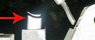
This is how the scheme turned out
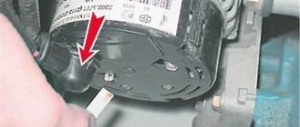
The yellow arrow is the lead of the upper brush to the diodes.
Result: work on connecting the three-level Enermash voltage regulator to the UAZ Patriot has been completed.
Modification of the generator Pramo-iskra 5122.3771-30 T for UAZ Patriot
We continue the series of programs about the “secrets” of the UAZ Patriot, or more precisely about what it costs us to build a car. The long-suffering 120A pramo-spark generator came under the knife. Everyone likes the stated maximum current of 120A, but not everyone likes how this generator works; we’ll work on one of the shortcomings today. First, a little theory and information about 120A, for us, for me, as the owner of a winch, and of course these 120A are not enough, and there are always few of them, and at low speeds it’s not enough at all, here is a graph of the speed dependence
But to compare the graphics of the BATE generator at 110A, it looks more profitable than the one directly.
the declared 120A is achievable at 8000 rpm. generator
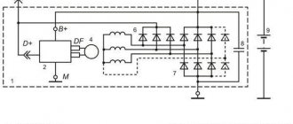
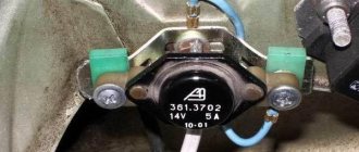
But the essence of my modification is not this, but the replacement of the useless regulator relay, which is no good, because... he doesn’t really know how to do anything. Previously, I installed a relay from the Energomash company with article number 611.3702-14, the same company produces 3-level relays. The schematic diagram of a standard relay looks like this:
The description of the operation of this unit looks like this: A voltage regulator with a brush unit is designed to maintain voltage
on-board network of the vehicle within specified limits in all operating modes of the electrical equipment system when changing the rotation speed of the generator rotor, electrical load, and ambient temperature. In other words, what will actually be there at the battery terminals is not known to this relay.
But progress does not stand still and it is possible to choose a relay with the ability to control the output voltage - this is much better! My choice fell on the relay with article number 846.3702 from , it is quite possible to select analogues from other factories, for example 9333.3702-04.
The description of the operation of this relay reads: “Multifunctional voltage regulator with brush assembly 846.3702 is designed for automatic regulation
voltage at the generator output within specified limits in all operating modes of the electrical equipment system, when changing the generator rotor speed, electrical load, and ambient temperature.” “To smooth out transient processes and reduce mechanical loads on the generator drive belt, the voltage regulator has the functions of smooth excitation of the generator and a smooth response to the connected electrical load with a maximum duration of 2.5 ± 0.5 seconds.”
846.3702 - the differences are obvious.
846.3702
846.3702
In terms of mounting points, it is identical to ours and fits without any problems. But because Since this relay compares favorably with the factory one, you will have to slightly modify the “horseshoe” generator, namely, turn off the built-in diodes. You can bite them off without removing them, in our version, without soldering the “horseshoe”, or you can carefully have a bite by removing the horseshoe.
we bite off the diodes.
Next, you need to power the + and phase of the relay. On the relay itself, I re-soldered the wiring to the B+ terminal in order to tighten it with a nut; I did not solder the connector to the W terminal. I tightened the self-tapping screw and it went in as it was.
all wires are in place.
We put everything back together, install the generator on the car and poke the tester into the battery; taking readings from the instrument panel is useless. The result of the work is with ALL possible consumers at XX, and I have them at 700-720 rpm. - this is a near, far, 4 spotlights on the roof + 2 side + 2 stoves at maximum, 12.85 V came to the battery terminals. As soon as the speed was raised to 900, the voltage rose to 13.3V, and already at 1500-2000 revolutions the voltage reached 14V. In static conditions at XX, with all consumers turned off, it confidently stood at 14.3V. I find this modification very useful.
https://www.drive2.ru/l/7553105/, https://www.drive.net/l/3771007, https://www.drive.net/l/5065215/, https://www. drive2.ru/l/5363950/, https://www.drive2.ru/l/3694987/
next article:
Installation of preheater UAZ Patriot
Task: install the Binar 5D Compact pre-heater for the UAZ Patriot. Bought directly from the manufacturer
Rating 4.00 [1 Vote]
Types of regulator relays
Before you independently repair the voltage regulation device, you must take into account that there are several types of regulators:
- external – increase the maintainability of the generator
- built-in – in the rectifier plate or brush assembly
- regulating by minus - an additional wire appears
- positive regulating – economical connection scheme
- for alternating current generators - there is no function for limiting the voltage on the excitation winding, since it is built into the generator itself
- for DC generators – an additional option for cutting off the battery when the internal combustion engine is not working
- two-level - obsolete, rarely used, adjustment by springs and a small lever
- three-level – supplemented with a special comparison device board and a matching indicator
- multi-level - the circuit has 3 - 5 additional resistors and a tracking system
- transistor - not used in modern cars
- relay – improved feedback
- relay-transistor - universal circuit
- microprocessor - small dimensions, smooth adjustment of the lower/upper threshold of operation
- integral - built into brush holders, therefore they are replaced after the brushes wear out
Operating principle of the regulator relay
Thanks to built-in resistors and special circuits, the relay is able to compare the amount of voltage generated by the generator. After which, too high a value leads to the relay being turned off, so as not to overcharge the battery and damage electrical appliances connected to the on-board network.
Any malfunctions lead to precisely these consequences: the battery becomes faulty or the operating budget increases sharply.
Summer/winter switch
Regardless of the season and air temperature, the operation of the generator is always stable. As soon as its pulley begins to rotate, electric current is generated by default. However, in winter the insides of the battery freeze, and it replenishes the charge much worse than in summer.
The summer/winter switches are either on the body of the voltage regulator, or the corresponding connectors are marked with this designation, which you need to find and connect the wiring to them depending on the season.
There is nothing unusual in this switch, these are just rough settings of the regulator relay, which allows you to increase the voltage at the battery terminals to 15 V.
Connection to the generator's on-board network
If, when replacing a generator, you connect a new device yourself, you need to take into account the following nuances:
- First you should check the integrity and reliability of the contact of the wire from the car body to the generator housing
- then you can connect terminal B of the regulator relay with the “+” of the generator
- Instead of “twists” that begin to heat up after 1–2 years of operation, it is better to use soldering of wires
- the factory wire must be replaced with a cable with a minimum cross-section of 6 mm2 if, instead of a standard generator, an electrical appliance rated for a current of more than 60 A is installed
- The ammeter in the generator/battery circuit shows which power source is currently higher in the on-board network
Regulator relay diagnostics
Voltage regulator failures can be determined by indirect signs. First of all, this is incorrect battery charging:
- overcharge - the electrolyte boils away, the acid solution gets on the body parts
- undercharging - the internal combustion engine does not start, the lamps are dimly lit
However, it is preferable to diagnose with instruments - a voltmeter or tester. Any deviation from the maximum voltage value of 14.5 V (in some cars the on-board network is designed for 14.8 V) at high speeds or the minimum value of 12.8 V at low speeds becomes the reason for replacing/repairing the regulator relay.
Built-in
Most often, the voltage regulator is integrated into the generator brushes, so a level inspection of this unit is necessary:
- After removing the protective cover and loosening the screws, the brush assembly is removed out
- When the brushes are worn out (less than 5 mm of their length remains), replacement must be carried out without fail.
- Generator diagnostics with a multimeter are carried out complete with a battery or charger
- The “negative” wire from the current source is closed to the corresponding regulator plate
- The “positive” wire from the charger or battery is connected to a similar relay connector
- the tester is set to voltmeter mode 0 - 20 V, the probes are placed on the brushes
- in the range of 12.8 - 14.5 V there should be voltage between the brushes
- when the voltage increases above 14.5 V, the voltmeter needle should be at zero
In this case, instead of a voltmeter, you can use a lamp, which should light in the specified voltage range and go out when this characteristic increases above this value.
The wire that controls the tachometer (marked W only on relays for diesel engines) is tested with a multimeter in tester mode. It should have a resistance of about 10 ohms. If this value decreases, the wire is “broken” and should be replaced with a new one.
Remote
There are no differences in diagnostics for the remote relay, but it does not need to be removed from the generator housing. You can check the generator voltage regulator relay with the engine running, changing the speed from low to medium, then high. Simultaneously with the increase in speed, you need to turn on the high beams (at a minimum), the air conditioner, the monitor and other consumers (at a maximum).
Thus, if necessary, the vehicle owner can replace the standard voltage regulator relay with a more modern modification of a built-in or remote type. Diagnostics of performance is available on your own with a regular car lamp.
Modification of the relay regulator YA112A (winter-summer)
I somehow didn’t complain about charging the battery - I had two relay regulators available: one for the winter, which gave out more voltage, and one for the summer, which gave out less.
I wanted to make one - universal. I decided to add a second increased voltage level to the “summer” regulator - a “winter-summer” switch. You didn't have to look far for an example. The Ya112B “tractor” relay-regulator has this capability due to an additional resistor and an output from it going to the “winter-summer” switch.
Schematic diagram of Ya112B
Switching circuit for voltage regulator YA112A
Test circuit for voltage regulators Ya112A and Ya112B
Using variable resistance R, we adjust the voltage from 12 to 16V. The light should stay on until ~14V, then go out. Let's find out whether the voltage regulator is working properly and what voltage it is set to. The resistance of the resistor depends on the power of the connected light bulb. It is better to use an adjustable power supply with a built-in voltmeter.
Voltage regulator circuit Ya112A
There are several modifications of voltage regulator circuits.
So, we take the Ya112A circuit and add the missing elements (capacitor C1 if necessary - it is not in the circuit diagram of the regulator (lower circuit), but it is present on the board of this modification).
I connected the LED in series with the resistor. Without an LED, the difference between summer and winter voltage is about 1 Volt (which seemed a bit much to me for my RR copy). With an LED, the winter voltage exceeds the summer voltage by about 0.7 Volts, and the LED also acts as an indication that the button is turned on.
The manufacturing process in iron went as follows:
Two tested controllers. On the left is winter, on the right is summer.
“Summer” in the process of selecting resistance and testing:
Soldered wires and a button with a resistor and LED under heat shrink:
We collect everything.
Tests on a car, the button is attached to the positive wire.
Good luck!
PS I found an unexpected application - when I need to “light” someone else’s car, I press the button. The process goes faster without any gas boost