Installing additional equipment on a car requires an increase in on-board voltage, so modifications to the VAZ 2110 generator (installation of a diode) will affect many. Modern domestic cars are increasingly equipped with additional equipment with each model. If the first VAZ models had generators providing a current of 40 amperes, today 80, 90 or even 100 amperes are becoming small.
Many owners independently install additional power consumers, such as car subwoofers, fog lights and the like.
Modification of the VAZ 2110 generator (installation of a diode) will be a pressing problem for them, so the need arose to write such an article. Carrying out such an improvement is not difficult and is accessible to anyone who knows how to hold a soldering iron, knows how to use a multimeter and can distinguish a semiconductor diode from a capacitor or resistor.
A few words about its structure
The generator set of this car is a fairly reliable device that can withstand vibration loads and temperature changes in the engine compartment. In addition, it is not afraid of moisture and dirt when moving. Its performance should be stable at any engine speed.
Generator requirements:
- The strength of the current generated by the device must be such that the battery is not discharged, but is charged to the required level, regardless of the connected utility networks;
- Regardless of engine speed and fluctuations in current consumption, the on-board voltage must be stable.
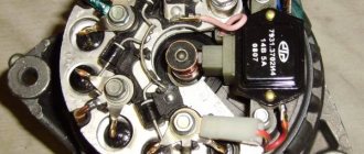
This is an electrical machine that converts the rotational motion of the motor shaft into direct voltage to charge the battery. Its body consists of two halves: front and back. The back cover is responsible for connecting the brush assembly with a relay regulator, a diode bridge and terminals for connecting consumers of the electric current generated on it.
The main element of this device is the stator, which generates electrical voltage. Installed between the body halves, front and rear. A rotor with an excitation winding rotates in a housing on bearings. Voltage to this winding is applied through the copper rings on the rotor shaft and supplied to them through a brush assembly mounted on the back cover.
Possible improvements. Today, lovers of additional consumers of electric current in a car have two ways to increase the battery charging voltage. Let's take a look at them.
Possible malfunctions: signs and causes
As stated above, the purpose of diode elements is to convert alternating voltage to direct voltage. If one of the diode elements fails, then its malfunction may be indicated by such a sign as a decrease in the voltage level, as well as power in the vehicle electrical network.
For what reasons may problems occur in the operation of the DM:
- Manufacturing defects. As practice shows, many modern DM manufacturers use aluminum shells of fairly low quality in their production. Accordingly, this affects their reliability as a whole. That is why it is recommended to use DM equipped with steel shells, since this directly affects the service life.
- Moisture gets inside the device. Regular exposure to moisture can cause oxidation, in particular, on the surface between the device body and diode elements.
- Engine fluid getting into the unit is one of the most common causes. Exposure to lubricant can lead to disruption of the functionality of the device as a whole, especially if it gets inside the generator unit, directly on the DM.
- Another reason why DMs on “tens” often fail is the polarity of the battery is reversed. If you connect the battery to a charger or accidentally reverse the polarity while “lighting up” the car, this will most likely cause the motor to burn out. Therefore, you should always remember that plus is connected to plus, and minus is connected to minus.
- Regular operation of a vehicle with a weak battery. If the battery does not pull the load and constantly operates under conditions of reduced charge, then the reason may be the inoperability of the DM.
Modification of the relay regulator
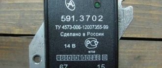
Any modification to a generator set requires at least a little knowledge of electronics. To modify the “relay” for a higher battery charging voltage, you need to purchase the same relay from a foreign car with an output voltage of 14.5 volts, it is indicated on the top cover. The further order will be as follows:
- it is necessary to disconnect the native “pill” from the home relay. It is necessary to use a heated soldering iron and tweezers;
- The same procedure is done with the imported “gadget”;
- Next, you need to install an imported relay on the household brush assembly. Here you will have to work hard, since the leads do not match and they need to be bent and welded correctly;
- After this, it is firmly fixed to the body with self-tapping screws, having previously been treated with a special heat-shrink paste.
- That's it, you can install a regulating relay on the generator and check it in action, it should produce a voltage equal to 14.5 volts.
Converting a car generator for a homemade windmill to permanent magnets
Hello, people often write to me about how best to make an axial disk generator, how many magnets there should be and how many coils. They ask what wire the coils should be wound with and how many turns. They ask about the ratio of magnets to coils, and how to connect the coils to each other. I will try to answer these questions, accompanying them with drawings...
>
How to install an additional diode?
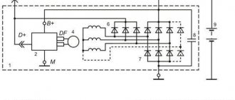
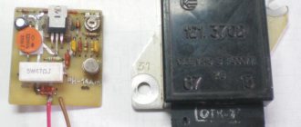
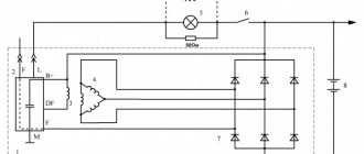
This is another way to modify the generator set to increase the battery charging voltage. This method is a little more complicated, since it will require complete disassembly of the generator. The modification consists of changing the connection of output D of the relay regulator.
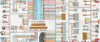
The diagram shows in red an additional diode that needs to be installed. The 2D219B device is suitable as such a semiconductor device, but you can choose a similar one with similar parameters.
you need to find about half a meter more of two-core cable, two No. 4 terminals “male” and “female”, as well as heat shrink. At one end of the wire, terminals are soldered and insulated with heat shrink. The free ends of the wire must be soldered to the diode, the “mother” to the cathode, and the “male” to the anode. Now you need to connect the “mother” to the PH terminal, and connect the standard wire to the “father”. This completes the conversion, all that remains is to assemble the device, install it on the car and carry out tests.
As you can see, the modification is not that difficult. Modifying the VAZ 2110 generator (installing a diode) will allow fans of loud music and additional lighting effects not to think that the battery is not charging enough.
Any motorist interested in the design of his iron horse knows that the main source of electricity in the electrical equipment of any car is the power plant, which includes a battery, a generator and a relay regulator. The drums are the main part of this trio. It powers the entire on-board network of the car and the generator using a relay-regulator, powers the battery as far as possible and necessary and ensures that the specified voltage in the on-board network of the car does not exceed the specified voltage (for cars with 12-volt equipment, this voltage is 14-14.6V , and for 24 volts - 27-28.8V). And although the generators in the car are “durable” devices, they still sometimes fail. Let's see what the Russian market offers us to replace a faulty generator, and at the same time we will test the proposed models in our testing laboratory.
To begin with, a small educational program. The generator is necessary for uninterrupted recharging of a constantly discharged battery with electrical devices connected to the vehicle’s on-board network. Generators are installed on modern cars. They fully meet the requirements for one of the most important transmissions in a car.
The generator converts the mechanical energy of the engine into electrical energy. The voltage regulator (in the vast majority of modern cars is an integral part of the generator, with rare exceptions when the regulator is “remote”, i.e., extended in the engine compartment, separately from the generator) keeps the car running when it is on. — mains voltage within the limits specified when changing the electrical load, generator rotor speed and ambient temperature.
The car generator must provide uninterrupted power supply and have sufficient power for:
- supply electricity to the battery, which is constantly discharged by consumers working on board;
- When all normal electricity consumers were turned on at low engine speeds, the battery did not discharge.
In addition, the generator must have sufficient strength, long service life, light weight and dimensions, low noise and radio interference.
Summarizing all of the above, we can conclude that the generator is the heart of the car’s electrical system, which must always “beat” and provide current for charging in order for the car to “live.”
Realizing the importance of this autounit, we paid attention to the domestic market of autogenerators.
For this comparison test, we purchased five car alternators from an auto parts store. These are generators of the brands KZATE, LKD, Fenox, Pramo and StartVOLT. All of them are designed for installation on VAZ car engines.
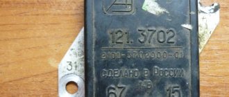
Generator 9402.3701-01 with built-in rectifier and analog voltage regulator (14 V; 80 A; 1.12 kW; 1200/6000 min -1; 4.9 kg) - JSC "A.M. Plant" Tarasov" (JSC "ZiT") - trademark of KZATE (Russia)
This generator is considered standard, since it is the generators of this plant that are supplied to the AvtoVAZ conveyor.
The build quality rating did not raise any complaints. The generator needs to be repaired.
A little about the evaluation methodology: to measure the current-voltage characteristics, the generators were installed on a specialized stand. Generators must provide maximum current at engine speeds from 1500 to 2500.
At 700 crankshaft revolutions per minute, this generator showed a current value in the range of 40 A with a predisposition to “damping”. When reaching the rated speed, the KZATE generator confirmed the declared 80 A and even reached 90 A. Assessing the reviews of car enthusiasts, we can say with confidence: this generator is a reliable classic option without claims to outstanding characteristics, but ensuring uninterrupted operation.
Testing the KZATE generator at 700 rpm crankshaft
Testing the KZATE generator at 2000-2500 crankshaft rpm
Generator 9402.3701 P with built-in rectifier and analog voltage regulator (14 V; 100 A; 1.4 kW; 1200/6000 min -1; 4.85 kg) - LKD Electrical (China)
The LKD generator almost completely repeats the design of the above-described KZATE generator. It has the same characteristics in terms of work quality and maintainability.
However, even when installed on the stand, the LCD generator showed its complete inoperability. When identifying the cause of the error, a lack of solder was discovered on the regulator relay power cable. While considering the future of the generator, we decided to exclude it from testing. Although it may take a few minutes to resolve the issue, we have decided to take the customer's side. After paying the money, the consumer should not independently eliminate the manufacturer’s defects or carry out major repairs on his own.
LCD generator lack of charge
We then asked about consumer reviews online about this generator and found other negative reviews on the topic, the only difference being that someone had to shell out a little more for it.
Generator AL 21305 with built-in rectifier and analog voltage regulator (14 V; 80 A; 1.12 kW; 1200/5500 min -1; 5.6 kg) – Fenox Global Group (Belarus)
The Fenox brand generator is identical in design to the two described above. However, upon inspection of this generator, higher quality workmanship was found. Maintainability at one level: requires the intervention of a qualified specialist. Knowing the “sores” of such generators, we checked the tightness of the contacts. As it turned out, not in vain. Do not squeeze them - the consequences will be sad, however, in the near future - melting of the contacts due to the transient resistances that arise when high currents pass, followed by failure of the unit. In fact, this is more prevention than crime. All generators have undergone this procedure.
Bench tests of the Fenox generator showed the following results. Working at 700 crankshaft revolutions per minute, it was possible to achieve values at the level of 45-50 A with obvious signs of “damping”. When the crankshaft rotation speed increased to 2500, the generator produced 90 A under load, but that was all.
Fenox generator test at 700 rpm engine crankshaft
Fenox generator tests at 2000-2500 crankshaft rpm
Generator 5102.3771 with built-in rectifier and analog voltage regulator (14 V; 100 A; 1.4 kW; 1200/5500 min -1; 5.4 kg) - JSC Concern Pramo (Russia)
The design of the Pramo brand generator is slightly different from the previous three: a different casting is used, a different design of bearing supports. Fastening bearings using flanges, among other things, has significantly increased the maintainability of the unit. To repair the bearing assembly of this generator, less qualified specialists may be involved.
The diode bridge of the generator also differs in design. The design exactly copies the design used in Bosch generators. But the diode bridge itself cannot be repaired. Welding of leads from the stator winding was carried out on a diode bridge. In general, maintainability is sacrificed for stable contact.
Bench tests of the Pramo generator showed the following results. Working at 700 crankshaft revolutions under load, it was possible to achieve a value of 50 A. By increasing the crankshaft revolutions to 2500, the generator reached a value of 100 A under load.
Pramo generator test at 700 rpm crankshaft
Testing the "Pramo" generator at 2000-2500 crankshaft rpm
Generator LG 0110 “StartVOLT” with built-in rectifier and digital voltage regulator (14.6 V; 120 A; 1.9 kW; 1200/5500 min -1; 5.3 kg) - Carvil LLC (St. Petersburg)
In design, the StartVOLT brand generator is very close to such representatives as KZATE, LKD and Fenox. Its diode bridge is similar to them, except for the presence of two additional power diodes, intended, as the developer states, to create an additional power take-off. This is the so-called use of the third harmonic, which is simply not used in other generators.
The stator winding cables do not have mechanical contacts. The stator winding cables are soldered to the diode bridge. The relay regulator, unlike all those described above, is digital and not analogue, again as stated by the manufacturer, and it is also assumed that, among other things, “a field-effect transistor is installed on the output switch, which has zero opening resistance, which guarantees reduction of losses."
The bearing units are also similar to those of the KZATE, LKD and Fenox generators.
And the most important significant difference from all previous models is the declared current of 120A!
We did not take the manufacturer’s word for it, but bench tests of the “StartVOLT” generator showed the following results: when the crankshaft was running at 700 rpm under load, it was possible to achieve 60 A load! In fact, this is almost 50% more than the standard KZATE generator.
Testing the "StartVOLT" generator at 700 rpm crankshaft
Testing the “StartVOLT” generator at 2000-2500 crankshaft rpm
So, let's sum up the intermediate results. With an almost identical design, the “strong side” of the StartVOLT generator made it possible to achieve 30-50% greater productivity than that of potential competitors. All we have to do is summarize the measurement data in a table, enter prices and expert assessments.
The classic model of a standard generator from the KZATE company is in demand among motorists, although it must be said that the increased demand for more powerful generators is a requirement of the time. Therefore, this model, despite its quality and the level of the manufacturer itself, is morally outdated. Therefore, our choice fell on the generator, as it is more interesting from the point of view of real characteristics.
As you know, additional equipment is often installed on a car, which receives additional voltage from the on-board network. Thus, the voltage indicator on the VAZ-2114 may drop to a critical level of 11 volts. If you also install optional air conditioning or heated seats, this may cause the starter to not have enough power to start the engine. How to solve a problem? Make sure that the voltage in the on-board electrical system increases.
Video about increasing the voltage in the on-board network on VAZ cars:
The video will tell you how to increase the voltage of the generator and on-board network with your own hands, and will also tell you about some of the nuances and subtleties of the process
How to identify electrical problems in a car?
The first step is to understand whether your car really has power problems. There are two groups of problems in this regard; roughly, all problems can be divided into problems during startup and strange operation of the electrical network after starting the engine
It is important to distinguish this because different modules are involved in these processes. It’s worth figuring out what symptoms of the car you should look for if the electrical network is not working well after starting the engine:
- the operation of all the lamps in the cabin, as well as the headlights, side lights and brake lights is too dim; this may not be very noticeable, but in reality the difference in brightness is noticeable;
- turning off some elements of the electrical network without permission under fairly heavy loads, for example, when the fan in the cabin is turned on, the music may turn off;
- when revving up at idle, the brightness of the interior lighting noticeably increases for a second, but when other equipment is turned on, the brightness decreases;
- perhaps a barely noticeable or annoying blinking of the light, uneven illumination of the road, rapid failure of light bulbs in various modules of your car;
- a decrease in fan speed is noticeably felt when optics, music or other power consumers are turned on; there may be an incorrect connection in the network.
The problem is that a car owner can easily get used to many such manifestations. And in this case there will be no surprises. You can get used to dim light, poor airflow and other troubles. But in general, this mode of operation is very harmful to your car. Sudden failure of the fuel pump, climate system, poor operation of the automatic transmission and other components is possible.
We increase the voltage - all options for solving the problem
Voltage in the on-board network after major repairs
So, many motorists may decide that the way out of this situation is to install a high-power generator, but in this case they will have to replace the battery with a more capacitive one. This is done in order not to “kill” the battery that is installed on the car, since overvoltage will lead to the destruction of the internal cells. This option is not suitable because it is too expensive.
The second option is to install an additional diode from another diode bridge or marked KD202V. This is much cheaper than replacing the alternator and battery, but does require some setup. To begin with, it is recommended to study the electrical circuits of the car and the generator design, as well as the charging circuit.
Installing the KD202V diode into the generator
When everything is ready, we proceed directly to installing a diode in the generator to increase the voltage in the on-board network. Let's consider the sequence of actions:
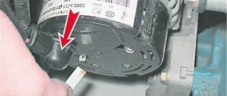
- Remove the back cover of the generator.
Remove the back cover from the generator
Wires and diode to increase voltage
We install heat shrink on the “male” and “male” threads.”
Installed heat shrink for solder part
We install a voltage regulator with a diode in the generator
We put the back cover on the generator and pull out the wires
As the measurements showed, after such an improvement, the voltage in the charged network was 12.2-12.5 volts.
Electrical diagrams and indicators
To further increase the voltage to at least 14 volts, a diode must be installed in circuit D, the voltage regulator. Any diode with a breakdown voltage of 20 V and a current of at least 5 A. The voltage drop is preferably no more than 0.6-0.7 V. A 2D219B diode is ideal.
How to find out the charge level of a car battery by its voltage
The simplest method is visual. Today, the degree of charge of the battery can be determined by looking at the hydrometric indicator (as it is called, the “eye”). Thanks to it, the degree of charge of the product is determined without improvised means:
The green color of the indicator indicates that the battery is charged more than 60%; dark color indicates the need to charge the battery; a light color indicates the battery's need for distilled water. You can also roughly determine the performance of the battery using a multimeter by measuring the voltage with the engine off, after leaving it for about 12 hours, as mentioned above. Measurements are carried out at a temperature of +18 C.
Here is a table of car battery charge by voltage:
| Performance level (%) | Voltage (V) |
| 100 | From 12.6 |
| 90 | 12,5 |
| 80 | 12,4 |
| 70 | 12,3 |
| 60 | 12,2 |
| 50 | 12,05 |
| 40 | 11,9 |
| 30 | 11,7 |
| 20 | 11,55 |
| 10 | 11,3 |
| 10,5 |
A mid-priced battery lasts approximately 3 years. If you follow the operating instructions all this time, the battery will not cause you any trouble. One of the main points here is to avoid deep discharge. After the three-year period, control over the battery should be strengthened: at least once every couple of weeks, measure the voltage of a fully charged battery, and, if possible, the density. After 4–5 years, it is recommended to replace the battery with a new one.
Source
Diagnostics
The diagnostic procedure must be carried out on a dismantled generator device, so the unit must first be removed. When the mechanism is dismantled, the plastic cover is removed from it, as mentioned above, the DM is located immediately behind it (the author of the video about self-diagnosis with a multimeter is Ramil Abdullin).
For diagnostics you will need a tester - a multimeter - the test is carried out as follows:
- First, the multimeter should be activated in ohmmeter mode. Having done this, the positive probe of the tester must be connected to the diode bus.
- In the same way, connect the negative probe of the tester to the corresponding contact on the diode bridge.
- Next, you need to monitor the tester readings. If the diode bridge is in working condition, then the tester display will show values close to infinity. If there are no such values, then most likely the DM is inoperative and should be replaced. But the diagnosis does not end there.
- Next, you will need to swap the location of the probes, that is, the negative contact is connected to the positive one and vice versa. Having done this, again look at the multimeter reading on the display. If there are no failures in the operation of the DM and the device as a whole is functioning normally, then a value of several hundred Ohms should appear on the tester screen.
- If the DM is equipped with an additional diode, then you can check it too. In this case, the diagnostic procedure is performed in a similar way; you just need to repeat all the steps.
Photo gallery “Self performance test”
DIY replacement instructions
In the event of a breakdown, the repair of the DM consists of its replacement, which is done as follows:
- First you need to turn off the ignition, open the hood and turn off the power to the on-board network; to do this, disconnect the battery.
- Once the battery terminal is reset, you will need to disconnect the pink cable responsible for activating the generator assembly. The wire itself is fixed with a bolt and nut; the nut itself will need to be unscrewed.
- Now you need to slightly loosen the tension on the top as well as the bottom nuts. Unscrew the tension screws and remove the strap. Inspect it - if the belt shows signs of damage - cracks, delamination - then it is better to change it immediately. If the strap is intact, set it aside.
- After completing these steps, you need to rotate the generator mechanism 90 degrees, this is done so that you can access the lower mounting screw. Unscrew it.
- Next, carefully inspect the body of the dismantled unit. Clean if necessary - there should be no dirt, especially on the connections. Dirt getting inside the generator housing can also lead to its incorrect operation and even failure. Bend the fasteners and remove the cover.
- Next, you need to clean the inside of the rings as carefully, but most effectively as possible.
- After this, all you have to do is dismantle the failed DM and replace it with a working part. When the installation is completed, the structure is assembled in the reverse order. Do not forget to tighten the strap, just make sure that it is not too tight, this is important. Having done this, you will need to start the engine of your car and diagnose the operation of the new DM.
Modification of the VAZ 2110 generator (installation of a diode). When there is something to do
Installing additional equipment on a car requires increasing the on-board voltage, so modifying the VAZ 2110 generator (installing a diode) will be of interest to many.
Modern domestic cars are increasingly equipped with additional equipment with each model. If the first VAZ models had generators providing a current of 40 amperes, today 80, 90, or even 100 amperes are becoming insufficient. Many owners independently install additional power consumers, such as car subwoofers, fog lights and the like.
Description of the diode bridge on the “Ten”
How is the diode modified and installed in the device? For what reasons can a bridge fail? To begin with, we suggest that you familiarize yourself with the description of the part. If you dismantle the generator assembly from the car and remove the cover, you will be able to see the diode bridge (DM), which is located immediately behind it.
Purpose and functions
What functions does the DM perform:
- The primary task of the device is to convert alternating current into direct current.
- The DM also performs the function of blocking current from entering the stator winding. In this case, the device actually performs the one-way valve option.
- In addition, the DM is designed to increase the safety margin of the generator unit. It allows you to protect the mechanism from the effects of adverse factors and contamination on the device, and this, in turn, can negatively affect the functionality of the mechanism as a whole.
Device
As for the device, in the factory configuration the DM for the “tenth” generator is a monolithic structure. This design, as a rule, is quite strong and reliable, is characterized by its small size, as well as a relatively low price. The only drawback characteristic of factory-made DMs is that if one of the diode elements burns out, local replacement of the damage will not be possible. That is, the car owner will have to completely change the factory axle with his own hands.
As for the design features itself, the DM consists of:
- two aluminum plates;
- spacers made of plastic;
- as well as nine diodes, which are connected to each other by soldering into one structure, that is, a bridge.
Assembling the motor control circuit
If necessary, you can continue the experiment and assemble a circuit to control a 3-phase motor with direct drive to the wheel.
For this:
- From the existing power steering unit of a car powered by a 3-phase motor, it is necessary to remove the unit with power transistors.
It will no longer be possible to use it as a full-fledged motor control module (BLDC).
- Next, the block of power transistors is connected to the 2CAN element via a homemade board equipped with transistor control drivers.
It can be done in a simple and quick way - using laser printing and an iron. The general connection diagram is shown in Figure 8.
Source we.easyelectronics.ru
Since not all pins of this element and the microcontroller are routed on the 2CAN board, you need to add more connections using surface mounting. The result is the design shown in the figure.