Lada K alina 2 . CHECKING AND REPLACING THE VOLTAGE REGULATOR ON THE CAR
You will need: a flat-blade screwdriver, 8", 12" wrenches, 7", "8", "24" socket wrenches, a hammer, a DC voltmeter, a megger.
The operation of the voltage regulator is to continuously automatically change the generator excitation current so that the generator voltage is maintained within specified limits when the rotation speed and load current change.
If necessary, you can check and replace the voltage regulator without removing the generator from the car.
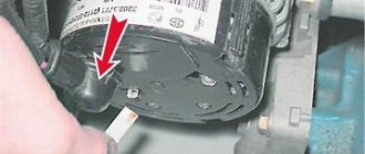
Shown is working on a car without air conditioning. On a car with air conditioning, a generator of a different model is installed, and to remove the relay-regulator, the generator must be removed from the car. 1. Move the rubber boot aside and connect the “plus” wire and the “minus” wire to the generator housing.
2. Start the engine and turn on the headlights.
3. After 15 minutes of engine operation at medium speed, measure the voltage; it should be 14.4-15.1 V. If undercharging or overcharging is observed (the voltage does not fall within the specified limits), replace the voltage regulator.
4. The serviceability of the capacitor can be checked with a megger or tester (on a scale of 1-10 MOhm). Connect the tester probes to the capacitor contacts. Before connecting, the device shows infinity. At the moment of connection, the resistance decreases, and then again tends to infinity. In this case, the capacitor is OK.
The faulty capacitor is replaced together with the rectifier unit as follows.
1. Disconnect the wire from the negative terminal of the battery. 2. Disconnect the wiring harness block from the generator terminals.
12. Check the serviceability of the voltage regulator. Connect a 12V test lamp to the brushes. Apply a voltage of 12 V “plus” to the terminal, and “minus” to the “ground” of the brush holder. In this case, the control lamp should light up.
13. Set the voltage to 15-16 V - the lamp should go out. If the lamp is on or off in both cases, then the regulator with brush holder is faulty and needs to be replaced.
14. Install the voltage regulator in the reverse order of removal.
As already mentioned in previous articles, the main malfunctions of the generator are failure of the diode bridge, brushes with a voltage regulator, or even an open circuit in the winding of the device. Below I will give some of the types of diagnostics using a multimeter that anyone can perform independently if they have this device.
Review of prices of generator manufacturers for the Lada Granta
| Manufacturer article number | Price, rub.) | Resource (thousand km) |
| KZATE 9402.3701-14 | From 4900 | 90 — 110 |
| BOSCH 21700-3701010-13 | From 5300 – 5500 | 90 — 110 |
*prices are current as of October 30, 2018.
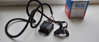
Recommendations for choosing a converter
In order to ensure stable operation of the power supply system, replace the standard KZATE converter with a BOSCH one. Despite identical technical characteristics, the workmanship of the latter is better.
Also, the BOSCH generator better “transfers” loads in the network from activated equipment, optics, and heaters.
The service life of both KZATE and BOSCH is within 90 – 110 thousand km. mileage Moderate loads and average driving speeds will increase the service life by 10 - 15%.
Door pinout for first generation Kalina
In all versions of the first generation Lada Kalina, the cable routing is the same.
Driver's door
- Output to the rear harness.
- A bundle of wires for connecting the speaker.
- Locking device.
- Driver's door control switch pinout element.
- Voltage to switch harnesses.
- Connection of the harness line to the mounting unit.
- Same as 5.
- Same as 6.
- Window regulator.
For front passenger
- Exit to the stern beam.
- Output to the appropriate speaker.
- Door lock drive.
- Electric window lift key.
- Power window control unit terminal harness.
- To the switch key of the corresponding node.
- Gearbox of the above device.
Rear doors
On the rear doors, the terminals are similar for both sides. Only two terminals are used here, where the first serves to connect to the rear electrical harness. The second is designed to supply an impulse and power to lock the doors.
Typical Lada Kalina pinout intended for the rear wiring harness
- Output to the rear door harness behind the driver.
- Voltage and indication of the rear left optical element.
- Same as 1 for the opposite side.
- Terminal for handbrake output.
- Kalina instrument pinout line.
- Output to the driver's door.
- Same as 5.
- Car interior lighting lamps.
- To the left turn signal.
- Connecting the fuel pump.
- Reverse transmission lock switch.
- Continuation of the highway from the front passenger door.
- Line articulation to the rear right speaker.
- Illumination lamp for the interior of the cargo compartment.
- Auxiliary stop.
- Alarm control unit.
- Same as 13 for the opposite side.
- Rear right turn.
- Output to rear optics located on the left side of the car.
- Output to cargo compartment wiring elements.
- Heated rear windshield.
Instrument panel pinout Kalina first generation
The decoupling is considered the most complex element of a car's electrical circuit. Here there are outputs from all important elements and assemblies of the machine:
- 1-5 – outputs responsible for connecting the front beam indication;
- 2.8 – similar for the stern;
- 6,7,9,10 – continuation of lines to the mounting unit and fuse-links;
- 11 – control lines for side, head and interior lights;
- 12 – combination instrument panel;
- 13 – keys for adjusting the heater cooler positions;
- 14 – for powering the air supply box;
- 15 – factory anti-theft element – ignition unit;
- 16 – immobilizer switch;
- 17 – part of the Kalina instrument panel pinout, responsible for indicating and supplying current to the ECM;
- 18 – onboard cigarette lighter;
- 19 – emergency warning button;
- 20 – brake light button located on the pedal;
- 21 – indicator on the windshield wiper system;
- 22 – rear window heating switch;
- 23 – power supply unit for turn signals and low/far modes of head optics;
- 24 – wiper control lever;
- 25 – horn button;
- 26 – supply voltage to the light bulb in the glove compartment;
- 27 – similarly, for the on/off key;
- 28-29 – pinout for Kalina radio – standard position:
- 30 – voltage to the heater cooler motor;
- 31 – resistor network of the above element;
- 32 – main pinout of Kalina EUR;
- 33 – lighting of the ventilation channel and stove.
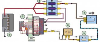
Front wiring harness pinout
- 1 – left head optics cable;
- 2-5 – connection chips to the dashboard;
- 6 – reverse gear activation locking element solenoid;
- 7 – key for activating the reverse gear lamp;
- 8 – voltage for starter;
- 9 – connector for connecting the line to the battery and starter;
- 10 – battery;
- 11 – electricity generator;
- 12 – the same as 1;
- 13 – relevant for hatchback, front window washer;
- 14 – washer motor;
- 15 – sensor for measuring temperature outside;
- 16 – powering the horn.
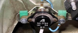
Integral charging relay Saransk KALINA (B) (gen. 9402.3701-06) (kb=21)
Multifunctional voltage regulator with brush assembly 849.3702 is designed to automatically regulate the voltage at the generator output within specified limits in all operating modes of the electrical equipment system, when changing the generator rotor speed, electrical load, and ambient temperature.
Design Features
- To smooth out transient processes and reduce mechanical loads on the generator drive belt, the voltage regulator has the functions of smooth excitation of the generator and a smooth response to a connected electrical load with a maximum duration of 2.5±0.5 seconds.
- The voltage regulator provides the ability to lightly indicate generator set faults by high and low voltage at the generator output, low voltage on the generator phase (for example, in the event of a break in the generator drive belt), as well as in the event of a short circuit in the excitation circuit.
Applicability
Cars VAZ-1117, VAZ - 1118, VAZ - 1119 Kalina, VAZ 2170, VAZ -2171, VAZ -2172, LADA GRANTA, etc. with generator 9402.3701-06.
Possibility of use
This voltage regulator is used in conjunction with rectifier limiting units without additional diodes as part of generators.
Reliability
In order to increase the reliability of the voltage regulator, it provides a number of protections against emergency modes: against short circuits in the excitation circuit, in the control lamp circuit, and overvoltage protection at the input of the voltage regulator.
Climatic performance
Voltage regulators are produced in climatic version O category 2 according to GOST 15150. The regulators meet the requirements for resistance to climatic influences according to GOST 25467. The regulators meet the requirements for electromagnetic compatibility of GOST 28751.
Technical characteristics of a multifunctional voltage regulator with a brush assembly (MFRN) 849.3702
| Technical data | 849.3702 |
| Operating temperature range, ? C | — 50 …+125 |
| Regulation voltage from the battery at t? = 25±10?C and generator load 5A, V | 14,25 … 14,75 |
| Maximum output circuit current, A | 5,0 |
| Thermal compensation coefficient Ureg, mV/?С | -7,0 ± 1,5 |
| Residual output voltage at current 5A, V | no more than 0.8 |
| Upper threshold of output indication, V | 16,1 … 17,2 |
| Lower threshold of output indication, V | 10,6 … 11,7 |
| Indication threshold for low phase voltage, V | 3,5… 8,0 |
| Duration of smooth load connection (LRC function), sec | 2,5 ± 0,5 |
| Maximum permissible long-term exposure to increased supply voltage, V | 30 |
| Maximum permissible pulse overvoltage according to GOST 28751, V | impulse type 5, severity level II, functional class B |
| Threshold current of protection along the excitation circuit, A | 7,0 … 12,0. |
| Threshold protection current along the indicator element circuit, A | 1,0 … 2,0. |
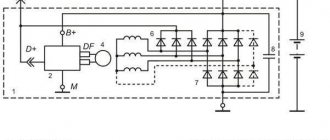
Connection diagram for multifunctional voltage regulators with a brush assembly (MFRN) 849.3702 as part of a generator set
- generator
- voltage regulator
- generator field winding
- stator winding
- indicator lamp or LED
- ignition switch contacts
- rectifier unit
- accumulator battery
Actions when charging disappears
The generator on a Kalina with air conditioning has more power than on cars without an air conditioning system. The design and faults are the same. What to do if charging is lost? Don't panic and check immediately:
Voltage regulator. The easiest and most expensive way is to replace it with a known good one. But you can also apply voltage of 12 V and 15 V to check operation. Regardless of whether the regulator is mechanical or electrical, it will behave the same. In the first case, voltage will be supplied to the excitation winding, but in the second - not. Alternator slip rings and brushes. You can use a simple lamp probe to check the contacts. The length of the brushes must be more than 5 mm, otherwise they should be replaced. The integrity of the field winding can be checked with a tester. Moreover, there is no need to remove the generator, just crawl up to the slip rings and check the resistance between them
Please note that they should not short to ground. The condition of the stator winding and diode bridge can be assessed only after dismantling the generator.
Checking the rectifier and winding integrity
The rectifier unit is checked using an ohmmeter or a test lamp. In the latter case, it is necessary to apply a positive voltage through the lamp to the “B+” terminal of the generator, and a negative voltage to the housing. If the lamp lights up, this indicates a short circuit in the rectifier unit.
If the lamp lights up when the negative (“+” remains on the “B+” terminal) is transferred to one of the windings, one or more diodes are faulty. A breakdown of the negative diodes is indicated by a burning lamp when a “plus” is applied through it to the winding terminal, and a “minus” is applied to the generator housing. You can exclude a short circuit or break in the stator winding using the same test lamp. When the winding terminals are connected to a voltage source, the lamp should light up, but when the terminals of different windings are connected, it should not.
You can also check for a short circuit in the windings using an ohmmeter. If, when the probes touch the leads of one winding, it shows infinity, there is a break. Similar readings when touching the terminals of different windings indicate the absence of a short circuit between them. Thus, you need to check each of the three windings. If they are ok, you need to replace the diode bridge.
The malfunction may also consist of a break in the rotor windings. To check, it is necessary to close the slip rings on the rotor shaft using ohmmeter probes or a test lamp with a voltage source. If the lamp does not light and the ohmmeter shows infinity, there is a break.
The main elements of an automobile voltage generator are a voltage regulator, a diode bridge, a rotor and a stator. Checking them individually will allow you to understand the cause of the malfunction. If the windings break, it is advisable to replace the generator assembly; the rectifier unit and voltage regulator can be purchased separately.
Source
Electrical equipment Lada Kalina
If the voltage regulator unit, capacitor and not a tight fit of the brushes are faulty, or if they are worn out, the vehicle's supply voltage deviates from the norm. In this case, it is necessary to check the above listed elements and, if necessary, replace them. In this article we will talk in more detail about diagnosing and replacing generator elements in a Lada Kalina car.
To remove the Lada Kalina voltage regulator you will need the following tool:
flat-blade screwdriver, 8mm and 10mm open-end wrenches and 7mm, 8mm and 24mm socket wrenches, hammer, soldering iron, universal meter (with DC voltmeter and megger)
Checking the functionality of the voltage regulator on the Lada Kalina generator
1. Move aside the rubber insulating boot of the positive terminal from the generator. 2. Start the engine and allow the engine to warm up so that the vehicle operates normally at idle speed. 3. Measure the voltage between the positive terminal and the body (negative terminal). The voltage should be 14.5-15.1 volts.
If there is a deviation from the specified range, the voltage regulator must be replaced. See also checking the Lada Kalina generator regulator in the section “Replacing the voltage regulator”
Checking the functionality of the Lada Kalina generator capacitor
The capacitor is usually checked with a specialized meggometer, since not all universal devices have a measurement of up to 10 MoM. The device is set precisely in the range of 1-10 MΩ. Before connecting to the capacitor, the device shows infinity. If connected to a working capacitor, it begins to charge and an electric charge accumulates on its plates - current flows and, accordingly, the resistance on the device drops. After charging it (saturating the capacitor plates), the resistance again becomes infinite.
Replacing the voltage regulator Lada Kalina
carried out as follows
1. Disconnect the negative cable from the battery. 2. Disconnect the excitation block from the generator.
3. Disconnect the positive terminal from the battery by unscrewing the nut.
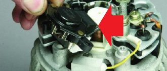
4. Remove the factory seal from one of the screws holding the plastic casing and remove the screws. Remove the protective plastic cover. 5. Remove the two screws securing the regulator and remove the voltage regulator.
6. Check the ease of movement of the brushes. They must protrude at least 5 mm from the voltage regulator housing. 7. You can check the voltage regulator by connecting a 12 V lamp to its outputs and applying a voltage in the range of up to 12 volts to its inputs, while the lamp should light and the voltage is more than 12 V to 16 V.
If the voltage is too high, the lamp should go out. If this algorithm does not work, then the regulator must be replaced. Installation of the regulator is done in the reverse order.
Replacing the rectifier unit with a capacitor Lada Kalina
1. Using a soldering iron, unsolder the six leads and remove the 3 bolts.
2. Remove the rectifier unit from the generator. Installation of the rectifier unit is carried out in the reverse order
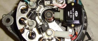
Checking diodes on the rectifier block Lada Kalina
1. Dodas are checked with a universal device. (6 diodes in total) Attach the black “negative” probe to the negative plate, and the positive “red” probe alternately to the three contact terminals of the diodes. The resistance should be 580-620 Ohms.
Attach the red “positive” probe to the negative plate, and the negative “black” probe alternately to the three contact terminals of the diodes. The resistance should be 580-620 Ohms.
Checking the windings of the Lada Kalina generator
1. Check the generator windings with a device. All windings should have approximately equal resistance, without significant deviations. Deviations indicate a break or short circuit.
Checking the combined relay-regulator
Checking the VAZ 2110 voltage regulator
To perform the corresponding check, it is necessary to assemble the circuit shown in the figure. To do this, use a charger or power supply with an adjustable load (it is important that it be used to regulate the voltage value in the circuit), a 12 V light bulb (for example, from a turn signal or headlight, with a power of 3.4 W), a multimeter, and the regulator itself voltage (this can be from a Bosch, Valeo or other generator). It is advisable to have the wires used for switching with “crocodiles”.
Checking the voltage regulator of the generator 37.3701: 1 - battery; 2 — ground terminal of the voltage regulator; 3 - voltage regulator; 4 – terminal “Ш” of the regulator; 5 — output “B” of the regulator; 6 — control lamp; 7 — terminal “B” of the voltage regulator.
If you assemble a circuit in which the voltage is at a standard value of 12.7 V, then the light bulb will simply glow. But if you use a voltage regulator to raise its value to 14.14.5 V, then if the relay is working, the light should go out. Otherwise the regulator is faulty. That is, when the voltage reaches 14.14.5 V (depending on the model of the machine and, accordingly, the regulator) and above, the light goes out, and when it drops to the same level, it lights up again.
Types of generator faults
Due to the fact that any generator is an electromechanical device, there will be two types of faults - mechanical and electrical.
The first includes the destruction of fasteners, housing, malfunction of bearings, pressure springs, belt drive and other failures not related to the electrical part.
Electrical faults include winding breaks, diode bridge faults, brush burnout/wear, turn-to-turn short circuits, breakdowns, rotor beating, and relay-regulator faults.
Often, symptoms that indicate characteristics of a faulty generator can also appear as a result of completely different problems. As an example, poor contact in the fuse socket of the generator field winding circuit will indicate a generator malfunction. The same suspicion may arise due to burnt contacts in the ignition switch housing. Also, the constant lighting of the generator malfunction indicator lamp can be caused by a breakdown of the relay; the blinking of this switching lamp may indicate a generator malfunction.
The main signs of a malfunctioning autogenerator:
- When the engine is running, the battery discharge warning lamp flashes (or stays on continuously).
- Discharging or overcharging (boiling) of the battery.
- Dim car headlights, a rattling or quiet beep when the engine is running.
- Significant change in headlight brightness with increasing speed. This may be acceptable when increasing the speed (re-throttle) from idle, but the headlights, having lit up brightly, should not increase their brightness any further, remaining at the same intensity.
- Extraneous sounds (howling, squeaking) coming from the generator.
It is necessary to regularly monitor the tension and general condition of the drive belt. In case of cracks and delaminations, immediate replacement is necessary.
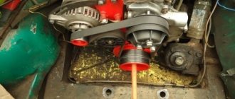
About the belt? car generator actions
The generator operation of the Lada Kalina unit is based on the following principle: an alternating current is subsequently induced in the stator winding, and the current is transformed into direct current through a rectifier module located on the body of the unit. The generator cover is also equipped with an electronic voltage regulator and a brush holder. device The rotor receives torque from the crankshaft pulley. A poly V-belt appears as a transmission link.
Among the basic characteristics of the generator installation there are the following parameters:
- maximum generated current – 85-90 Amperes;
- operating range of onboard voltage – 14.4-15.1 Volts;
- rotation ratio of the rotor and motor – 1:2.4;
- right-hand direction of rotation.
The housing is held together by pins that tighten the covers onto the stator. In the mounting sockets of the indicated covers, bearings are present, due to which the ability of the rotor to rotate is ensured. The rear bearing is installed inside the cover with a minimum gap. The front element is endowed with the ability to slide along the surface of the shaft and is fixed. It has a rotor inside the front cover with a small one on the outside, and the pressure plate covers it with tension. part The rear of the device is protected by a plastic casing.
diagram to Let's move on to switching the generator with the on-board network. connections The scheme is very simple. After turning on the voltage regulator, the ignition voltage begins to supply power to the circuit through the battery discharge indicator lamps. When the motor starts, the excitation winding is supplied with power from three diodes mounted in the rectifier unit.
indicated Using a signal lamp, you can check the generator unit. If the device is working properly, the lamp lights up when the ignition is turned on. When the engine starts, it goes out. When such a phenomenon does not occur and the lamp continues to shine, the generator installation should be diagnosed for the presence of malfunctions. In some cases, replacement is required, and many are interested in whether to remove the generator?
Checking the rectifier unit (diode bridge)
To perform this diagnostic, it is necessary to remove the diode bridge from the Kalina generator; this was described in more detail in previous articles in this section.
Then we connect the tester with the black wire to the negative plate of the block, and the red one in turn to the three contact terminals of the diodes. This way we check all the rectifiers in the block. The values on the device should be in the range from 400 to 800 Ohms. Personally, on my Kalina, during this test, all diodes showed a resistance within 535 Ohms. But the repair instructions from the Third Rome publishing house talk about numbers of 580-620 Ohms. I will say right away that when I rang two serviceable generators, the values specified in the manual were not achieved, although there were no problems with charging, so I personally doubt the accuracy of the data in this instruction.
Then we carry out the same operation, only swapping the contact wires of the multimeter. In this case, the device, with working diodes, will show infinity, that is, its readings will not change:
How to remove the generator on the LADA Granta
The “Grants” generator has to be removed for various reasons: for repair, maintenance, modification of the unit. You can do this without the help of others if you know how to remove the generator on the Grant. Depending on the modification of the car (8 or 16 valve engine, presence of air conditioning), the procedure for dismantling the generator has its own characteristics, so it is worth considering each option separately.
How to remove a generator on an 8-valve Grant without air conditioning
The following will be useful for work:
Before removing the generator on a Grant without an air conditioner, you should disconnect the ground from the battery by removing the negative terminal. The procedure is as follows:
- unscrew the 2 rear bolts securing the motor protection;
- unscrew the 4 front motor protection bolts;
- remove the engine protection (mudguard) from the car;
- disconnect the wiring block from the generator;
- remove the protective cap of the nut holding the power wire;
- unscrew the nut and disconnect the generator power cable;
- unscrew the top nut securing the “Grant” generator;
- press out the generator with a mounting spatula and remove the upper mounting bolt;
- unscrew the lower bolt securing the generator;
- move the generator away from the engine with a mounting blade and remove the lower mounting bolt;
- move the generator towards the right mudguard;
- remove the generator belt from the unit pulley;
- pull out the generator;
- Remove the alternator belt from the crankshaft pulley.
To put the LADA “Grant” generator in place, you need to perform the steps in reverse order.
Important: when installing the generator belt, make sure that the pulley grooves and the groove tracks on the belt match
How to change the generator on a 16-valve Grant
The generator mount on the 16-valve Granta variation is distinguished by the presence of a belt tensioning mechanism. Therefore, the procedure for replacing the generator on this model is slightly different. To work, you will need socket wrenches 8, 10 and 13. As when dismantling the generator from the 8-valve Granta, before starting work you need to remove the ground terminal from the battery to eliminate the possibility of a short circuit.
We remove the Lada Kalina generator and change the armature contact rings.
https://youtube.com/watch?v=gVC1DyDADBk
How to remove a 16kL generator. Kalina. If you have any questions, you can ask them in the VKontakte group -…
After this, you need to remove the engine protection by unscrewing the 4 front and two rear bolts securing it to the body parts. The 16-valve “Granta” generator is removed as follows:
- disconnect the block from terminal “D” on the generator;
- remove the rubber cap covering the “B+” terminal of the generator;
- Using a 10mm wrench, unscrew the nut holding the wire tip;
- loosen the tension bar nut using a 13mm wrench;
- by rotating the tensioner adjusting bolt counterclockwise, loosen the tension on the Grant generator belt (a 10mm socket wrench is required);
- move the generator towards the engine and remove the belt from the pulleys;
- Unscrew and remove the adjusting bolt of the belt tension mechanism from the generator mounting bracket;
- remove the tension bar;
- unscrew the lower nut securing the “Grant” generator;
- remove the spacer bushing and remove the lower mounting bolt;
- remove the tension bar;
- pull out the LADA Granta generator.
To install the generator, you need to do the above in reverse order.
Important: after installing the 16-valve LADA “Grant” generator, it is necessary to adjust the belt tension
How to remove a generator on a Grant with air conditioning
The LADA Granta air conditioner is driven by a generator belt, which complicates the operation. You must first move the air conditioner to the side, and then proceed to remove the generator. To work you will need:
First, as usual, you will have to disconnect the ground from the battery. Removing the generator on a Grant with air conditioning is done as follows:
- treat the bolts holding the engine mounts and bracket with WD-40;
- dismantle the protection by unscrewing the fastening bolts;
- when the WD-40 product takes effect, unscrew the bracket nut;
- place a jack under the right front part of the car;
- loosen the bolts holding the front right wheel;
- raise the jack, hanging the wheel;
- remove the wheel from the car;
- unscrew the tension roller;
- unscrew the bolts securing the pillow;
- carefully lower the car, hanging it (the cushion will move towards the engine, opening access to the belt and generator).
Next, it remains to remove the generator using one of the methods described above.
The procedure for installing the generator is the reverse of the procedure for dismantling. After installing the generator, you need to screw on the cushion, install the engine protection and wheel, and attach the ground terminal to the battery.
Installation and repair features
Installation occurs in reverse order. If necessary, the generator is replaced or repaired. In some cases, repair will be impractical, since there are many unusable components, including stator and rotor windings. Restoration will be expensive; it will be much easier to completely replace the generator on Kalina. The cost of a new generator in stores is 4-5 thousand rubles. At "showdown" you can buy it 2-3 times cheaper.
Lada Kalina dashboard diagram
1,2,3,4 — blocks of the instrument panel wiring harness to the blocks of the rear wiring harness;
5,6 — blocks of the instrument panel wiring harness to the blocks of the front wiring harness; 7 — block of the instrument panel wiring harness to the block of the wiring harness 8 — block of the instrument panel wiring harness to the block of the front wiring harness; 9 — lighting control module; 10 — ignition switch; 11 — on-board computer mode switch; 12 — windshield wiper switch; 13 — sound signal switch; 14 — light signaling switch; 15 — instrument cluster; 16 — evaporator temperature sensor; 17 — interior air temperature sensor; 18 — air conditioner switch; 19 — controller of the automatic climate control system; 20 — heater damper gearmotor; 21 — rear window heating switch; 22 — alarm switch; 23 — brake signal switch; 24 — cigarette lighter; 25 — electric amplifier control unit; 26,27 — blocks of the instrument panel wiring harness to the radio; 28 — backlight lamp for the heater control panel; 29 — illuminator; 30 — mounting block: 31 — heater electric motor switch; 32 — heater electric motor; 33 — additional resistance of the heater electric motor; 34 — lampshade lighting of the glove box; 35 — glove box lighting switch; 36 — control unit of the APS-6 automobile anti-theft system; 37 — driver airbag module; 38 — passenger airbag module; 39.40 — blocks of the instrument panel wiring harness to the blocks of the ignition system wiring harness. KZ - additional starter relay; K4 - additional relay; K5 - relay-interrupter for direction indicators and hazard warning lights; K6 - windshield wiper relay; K7 - headlight high beam relay; K8 - sound signal relay; K9 - relay for turning on fog lights; K10 — relay for turning on the heated rear window; K11 — electric seat heating relay; K12 - air conditioning compressor clutch activation relay;
Instrument panel wiring harness - 11186-3724030-20.
generator viburnum
Post by sea » January 28, 2014, 12:00
Post by puh » Jan 28, 2014 01:46 pm
Post by Parodist » Jan 29, 2014, 02:52 p.m.
Post by Sasha-Irpen » 30 Jan 2014, 06:38
Post by puh » 30 Jan 2014, 08:53
Post by Sasha-Irpen » 30 Jan 2014, 10:23
Honestly, it’s a pity to waste time explaining basic truths, but since I seem to have chewed everything out in great detail (especially since such information is not secret and is on the Internet), I’ll explain it again, but more slowly. (For those in the tank).
There are generally accepted digital symbols in electrical circuits. 1). The direct “+” of the battery is usually designated as “30” and, most often, purple (red) wires are used for this bus. For example, on the generator, near the power bolt you can see the designation “30”. If you have noticed, when the ignition is turned off, on some sensors with an oscillator with an input voltage of 1 mOhm, you can see a voltage of several volts. BUT, can we say that they have a “30” tire? 2). The voltage appearing after the ignition switch is usually designated “15”. (Options 15/1, 15/2 are possible). On a VAZ this is a wire, usually blue (possibly with a black stripe). On the contact group of the ignition switch you can see both 30 and 15 and even 50. (“50” is the starter retractor). In my understanding, bus “15” is a voltage of approx. 12 volts, which appears after turning on the ignition and is capable of powering a load of several amperes. 3). On the decimal generator, near the 6.3 mm plug, it says D+, or “61”. So 61 is a bus for excitation of the generator; on a VAZ it is connected with a brown wire with a white stripe and has nothing in common with bus 15, since it has its own name - 61. If, with the ignition on, measure the voltage on this plug, its value will be from 1 to 3 volts. This is another confirmation that this is not a “15” tire. If you try to connect a load to this wire (even a light bulb from the dimensions), then this light bulb will not light up, and the maximum that can be achieved is that the light bulb on the instrument panel with the battery drawn will light up. 4). I hope that there is no need to talk about tires “31”, “49”, “56”, “58”, etc.? Dear, it seems that you have small gaps in your knowledge, so it’s better to learn the materiel.
On Kalina cars, the generator is three-phase and produces alternating current. There is no need to go into too much theory; an ordinary motorist only needs to know how to independently diagnose and repair the installation. This means installing the generator and voltage regulator directly. The fact is that at the output of the power windings the voltage jumps in the range of 10-30 V, and to power the entire on-board network you need 12 V. The first step is to rectify the voltage and then stabilize it.
Classification of generator faults
Since a car generator is an electromechanical device, its main faults are divided into two categories - electrical and mechanical. Electrical faults include breakdowns of the diode bridge, interturn short circuits, damage to the windings, breakdowns of the relay regulator, burnout of brushes and their wear, as well as breakdowns.
But mechanical malfunctions include damage to fasteners, problems with bearings, destruction of the generator housing, disruption of the correct operation of the belt drive and other malfunctions that have no connection with the electrical “stuffing” of the generator.
Very often, signs indicating a generator breakdown are caused by completely different problems that appeared earlier. For example, a generator malfunction may be the result of burnt contacts located in the ignition switch housing. Sometimes the light indicating that the generator is not working is lit due to a broken relay.
Typical signs of a faulty generator in a car:
- The battery is being overcharged or discharged.
- When the engine is running, the battery discharge light is on or flashing.
- Significant increase in headlight brightness with increasing speed. This can happen during revving after idling, but the brightness of the headlights cannot increase constantly.
- The sound signal is too weak, the headlights are not bright enough when the engine is running.
- The presence of specific sounds that the generator makes.
Experts recommend periodically checking the tension of the generator drive belt and monitoring its condition. If the slightest defects, such as cracks, appear, the belt must be replaced.
Reasons why the indicator does not light up
It is extremely important to be able to independently find out the causes of the problem, as well as study ways to eliminate it. In fact, there are many reasons why a light bulb fails.
However, you will have to check all the options in order to come to the only correct decision.
As a rule, the initial knowledge of an auto electrician is enough to carry out the inspection. As mentioned above, there are several reasons, but they are divided into two categories: harmless and dangerous.
A dangerous cause that requires immediate repair is a circuit malfunction or breakage. As for harmless reasons, this is a banal light bulb burnout, battery discharge, etc.
Along with this, the same reason can turn from harmless to dangerous
And this is important to understand
Battery discharge
If, at the same time that the battery light does not light up, the dashboard instruments do not turn on or are dimly lit, then this is a clear sign of a low battery. The problem can be “cured” by simply charging the battery.
Replacing generator brushes for Lada Kalina sedan (VAZ Kalina)
If the voltage regulator unit, capacitor and not a tight fit of the brushes are faulty, or if they are worn out, the vehicle's supply voltage deviates from the norm. In this case, it is necessary to check the above listed elements and, if necessary, replace them. In this article we will talk in more detail about diagnosing and replacing generator elements in a Lada Kalina car.
To remove the Lada Kalina voltage regulator you will need the following tool:
flat-blade screwdriver, 8mm and 10mm open-end wrenches and 7mm, 8mm and 24mm socket wrenches, hammer, soldering iron, universal meter (with DC voltmeter and megger)
Checking the functionality of the voltage regulator on the Lada Kalina generator
1. Move aside the rubber insulating cover of the positive terminal from the generator.2. Start the engine and allow the engine to warm up so that the vehicle operates normally at idle speed.3. Measure the voltage between the positive terminal and the body (negative terminal). The voltage should be 14.5-15.1 volts.
If there is a deviation from the specified range, the voltage regulator must be replaced. See also checking the Lada Kalina generator regulator in the section “Replacing the voltage regulator”
Checking the functionality of the Lada Kalina generator capacitor
The capacitor is usually checked with a specialized meggometer, since not all universal devices have a measurement of up to 10 MoM. The device is set precisely in the range of 1-10 MΩ. Before connecting to the capacitor, the device shows infinity. If connected to a working capacitor, it begins to charge and an electric charge accumulates on its plates - current flows and, accordingly, the resistance on the device drops. After charging it (saturating the capacitor plates), the resistance again becomes infinite.
Replacing the voltage regulator Lada Kalina
carried out as follows
1. Disconnect the negative cable from the battery.2. Disconnect the excitation block from the generator.
3. Disconnect the positive terminal from the battery by unscrewing the nut.
4. Remove the factory seal from one of the screws holding the plastic casing and remove the screws. Remove the protective plastic cover.5. Remove the two screws securing the regulator and remove the voltage regulator.
6. Check the ease of movement of the brushes. They must protrude at least 5 mm from the voltage regulator housing.7. You can check the voltage regulator by connecting a 12 V lamp to its outputs and applying a voltage in the range of up to 12 volts to its inputs, while the lamp should light and the voltage is more than 12 V to 16 V.
If the voltage is too high, the lamp should go out. If this algorithm does not work, then the regulator must be replaced. Installation of the regulator is done in the reverse order.
Replacing the rectifier unit with a capacitor Lada Kalina
1. Using a soldering iron, unsolder the six leads and remove the 3 bolts.
2. Remove the rectifier unit from the generator. Installation of the rectifier unit is carried out in the reverse order
Checking diodes on the rectifier block Lada Kalina
1. Dodas are checked with a universal device. (6 diodes in total) Connect the black “negative” probe to the negative plate, and the positive “red” probe alternately to the three contact terminals of the diodes. The resistance should be 580-620 Ohms.
Attach the red “positive” probe to the negative plate, and the negative “black” probe alternately to the three contact terminals of the diodes. The resistance should be 580-620 Ohms.
Checking the windings of the Lada Kalina generator
1. Check the generator windings with a device. All windings should have approximately equal resistance, without significant deviations. Deviations indicate a break or short circuit.
Any electrical equipment fails sooner or later. Thus, the most common generator malfunction on the Lada Kalina remains the regulator relay. Replacing this element is not difficult, but requires certain knowledge and skills.
Video on replacing the voltage regulator relay on a Lada Kalina:
This video story tells about replacing the generator regulator relay on a Lada Kalina, the nuances of installation and configuration.
Checking an Individual Regulator
Checking the voltage regulator of the G-222 generator: 1 - battery; 2 - voltage regulator; 3 - control lamp.
As a rule, separate voltage regulators were installed on old cars, including domestic VAZs. But some manufacturers continue to do this to this day. The verification process is similar. To do this, you need to have a power supply with a voltage regulator, a 12 V light bulb, a multimeter and a directly tested regulator.
To check, you need to assemble the circuit shown in the figure. The process itself is similar to the one above. In normal condition (at a voltage of 12 V), the light bulb lights up. When the voltage value increases to 14.5 V, it goes out, and when it decreases, it lights up again. If during the process the lamp lights up or goes out at other values, it means that the regulator has failed.
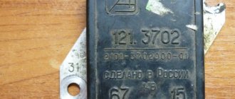
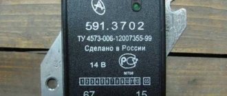
Checking relay type 591.3702-01
Relay test diagram type 591.3702-01
You can also still find a voltage regulator of type 591.3702-01, which was installed on rear-wheel drive VAZs (from VAZ 2101 to VAZ 2107), GAZ and Moskvich. The device is mounted separately and installed on the body. In general, the test is similar to that described above, but the differences are in the contacts used.
In particular, it has two main contacts - “67” and “15”. The first of them is a minus, and the second is a plus. Accordingly, to check it is necessary to assemble the circuit shown in the figure. The verification principle remains the same. In normal condition, at a voltage of 12 V, the light bulb lights up, and when the corresponding value increases to 14.5 V, it goes out. When the value returns to its original value, the light comes on again.
A classic regulator of this type is a device of the PP-380 brand, installed on VAZ 2101 and VAZ 2102 cars. We provide reference data regarding this regulator.
| Adjustable voltage at regulator and ambient temperature (50±3)° C, V: | |
| at the first stage | no more than 0.7 |
| on the second stage | 14,2 ± 0,3 |
| Resistance between plug “15” and ground, Ohm | 17,7 ± 2 |
| Resistance between plug “15” and plug “67” with open contacts, Ohm | 5,65 ± 0,3 |
| Air gap between armature and core, mm | 1,4 ± 0,07 |
| Distance between second stage contacts, mm | 0,45 ± 0,1 |
Testing a three-level relay
Regulated power supply
Some car owners install on their cars, instead of standard “chocolate bars,” three-level relays, which are technologically more advanced. Their difference is the presence of three voltage levels at which the battery power is cut off (for example, 13.7 V, 14.2 V and 14.7 V). The appropriate level can be set manually using a special regulator.
Such relays are more reliable and allow flexible adjustment of the cutoff voltage level. As for checking such a regulator, it is completely similar to the procedures described above. Just do not forget about the value that is set on the relay, and accordingly, check it with a multimeter.
Generator check
There is one method by which you can check the performance of a car generator equipped with a regulator relay 591.3702-01 with diagnostic elements. It is as follows:
- disconnect the wires that went to pins 67 and 15 of the voltage regulator;
- connect a light bulb to it (excluding the regulator from the circuit);
- Remove the wire from the positive terminal of the battery.
If, as a result of these actions, the engine does not stall, then we can say that the car’s generator is in order. Otherwise, it is faulty and needs to be checked and replaced.
How to remove the generator on the LADA Granta
The “Grants” generator has to be removed for various reasons: for repair, maintenance, modification of the unit. You can do this yourself if you know how to remove the generator on the Grant. Depending on the modification of the car (8 or 16 valve engine, presence of air conditioning), the procedure for dismantling the generator has its own characteristics, so it is worth considering each option separately.
How to remove a generator on an 8-valve Grant without air conditioning
To work you will need:
- socket wrenches for 8, 10 and 13;
- mounting blade.
Before removing the generator on a Grant without air conditioning, you should disconnect the ground from the battery by removing the negative terminal. The procedure is as follows:
- unscrew the 2 rear engine protection mounting bolts;
- unscrew the 4 front engine protection bolts;
- remove the engine protection (mudguard) from the car;
- disconnect the wiring block from the generator;
- remove the protective cap of the nut holding the power wire;
- unscrew the nut and disconnect the generator power cable;
- unscrew the top nut securing the “Grant” generator;
- press out the generator with a mounting spatula and remove the upper mounting bolt;
- unscrew the lower bolt securing the generator;
- move the generator away from the engine with a mounting blade and remove the lower mounting bolt;
- move the generator towards the right mudguard;
- remove the generator belt from the unit pulley;
- pull out the generator;
- Remove the alternator belt from the crankshaft pulley.
To put the LADA “Grant” generator in place, you need to perform the steps in reverse order.
Important: when installing the generator belt, make sure that the pulley grooves and the groove tracks on the belt match
How to change the generator on a 16-valve Grant
The generator mount on the 16-valve Granta variation is distinguished by the presence of a belt tensioning mechanism. Therefore, the procedure for replacing the generator on this model is slightly different. To work, you will need socket wrenches 8, 10 and 13. As when dismantling the generator from the 8-valve Granta, before starting work you need to remove the ground terminal from the battery to eliminate the possibility of a short circuit.
After this, you need to remove the engine protection by unscrewing the 4 front and two rear bolts securing it to the body parts. The 16-valve “Granta” generator is removed as follows:
- disconnect the block from terminal “D” on the generator;
- remove the rubber cap covering the “B+” terminal of the generator;
- Using a 10mm wrench, unscrew the nut holding the wire tip;
- loosen the tension bar nut using a 13mm wrench;
- by rotating the tensioner adjusting bolt counterclockwise, loosen the tension on the Grant generator belt (a 10mm socket wrench is required);
- move the generator towards the engine and remove the belt from the pulleys;
- Unscrew and remove the adjusting bolt of the belt tension mechanism from the generator mounting bracket;
- remove the tension bar;
- unscrew the lower nut securing the “Grant” generator;
- remove the spacer bushing and remove the lower mounting bolt;
- remove the tension bar;
- pull out the LADA Granta generator.
To install the generator, you need to do the above in reverse order.
Important: after installing the 16-valve LADA “Grant” generator, it is necessary to adjust the belt tension
How to remove a generator on a Grant with air conditioning
The LADA Granta air conditioner is driven by a generator belt, which complicates the operation. You must first move the air conditioner to the side, and then proceed to remove the generator. To work you will need:
- socket wrenches for 8, 10, 13 and 18;
- wheel wrench;
- jack;
- WD-40 product.
First, as usual, you will have to disconnect the ground from the battery. Removing the generator on a Grant with air conditioning is done as follows:
- treat the bolts holding the engine mounts and bracket with WD-40;
- dismantle the protection by unscrewing the fastening bolts;
- when the WD-40 product takes effect, unscrew the bracket nut;
- place a jack under the right front part of the car;
- loosen the bolts holding the front right wheel;
- raise the jack, hanging the wheel;
- remove the wheel from the car;
- unscrew the tension roller;
- unscrew the bolts securing the pillow;
- carefully lower the car, hanging it (the cushion will move towards the engine, opening access to the belt and generator).
Next, it remains to remove the generator using one of the methods described above.
The procedure for installing the generator is the reverse of the procedure for dismantling. After installing the generator, you need to screw on the cushion, install the engine protection and wheel, and attach the ground terminal to the battery.
Main process
Replacing the generator in the case of Kalina with an 8-valve or 16-valve engine involves performing the following steps:
- First of all, you will need to install the car on the repair site and fix the position of its wheels using wheel chocks. It is also necessary to turn off the engine and disconnect the terminals from the battery to ensure the safety of the work being carried out.
- After this, you need to loosen the belt tensioner roller, which fixes the position of the generator. To do this, you will need to unscrew the fasteners and dismantle them.
- The next step is to disconnect the plug secured by a plastic latch. To remove it, you need to lightly press it and pull it to the side. If everything is done correctly, the plug can be removed without problems.
- You will also need to remove the wire terminals located under the protective cap. Therefore, the car owner will first need to dismantle the protective cap by prying it off, and only then remove the terminals.
- The next step is to unscrew the nut securing the upper part of the generator. It is considered the most complex process among those listed, and it is better to familiarize yourself with the structure of the car in advance so that no problems arise. To make the nut give way quickly, you can move it with a wrench and then work it with a ratchet handle. Finally, all that remains is to lightly tap the protruding bolt so that it moves, after which you can remove it from the reverse side.
- Once the top bolt of the generator is removed, you can proceed to the bottom one. The actions are the same - a knob, a ratchet handle, a light knock and dismantling. However, in this case, it is recommended to hold the nut on the reverse side so that it does not turn.
- Next, you should begin dismantling the rod. This should be done carefully and carefully, since there are bearings and bushings inside. They will need to be held so that they do not fall and get lost.
The final step will be to dismantle the generator, clean the internal space of dirt, rust, possible traces of oil, and install a new unit - a standard generator or its equivalent.
You can check the functionality of the generator with a multimeter by connecting it to the battery terminals. The voltage reading should not be less than 13.4 volts.
The pitfall when replacing a Lada Kalina generator with air conditioning is its changed position, so you will have to approach it from the other side.
Thus, in order not to have to change the generator frequently, it is recommended to regularly inspect the technical condition of the car and, if necessary, repair certain parts, devices, and systems. Undoubtedly, repairs will cost the owner of Kalina somewhat less than buying new spare parts and entire units.
The generator must always be in good working order
Any modern car is equipped with electrical equipment that is absolutely necessary for the vehicle:
- without a starter it is impossible to start the engine;
- a car cannot be driven without lighting at night;
- The heater motor creates heat in the cabin;
- The wiper motor clears the windshield of rain and snow;
- FM radio makes it possible for the driver not to get bored on the road.
But all these devices cannot work without electricity, so the car must have a power source.
The current from which all consumers in the car are powered is produced by the generator, and the performance of the entire electrical circuit of the vehicle depends on its condition.
Therefore, the generator must always be in good working order, and if any breakdowns occur with it, they must be eliminated in a short time.
Types of Voltage Regulators
Having understood what types of these devices there are, what their features and properties are, a complete understanding of the procedures carried out during testing will come. This will also give the answer to what scheme, in what way and how to check the generator voltage regulator. There are two types of regulators:
In the first case, it is meant that the regulator housing is combined with the brush assembly directly in the generator housing. In the second case, the regulator is a separate unit, which is located on the car body, in the engine compartment, and wires from the generator go to it, and wires from it go to the battery.