A three-phase voltage regulator (charging relay) is installed on the generator. Responsible for maintaining the voltage of the on-board network within a given limit in all operating modes.
The output voltage may be affected by changes in rotor speed, electrical load, and ambient temperature.
Failure is considered one of the most common problems associated with the operation of the generator. Replacing an element does not require practical skills.
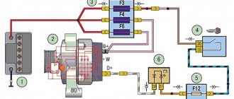
General diagram of electrical equipment of VAZ 1118
1 — block headlight; 2 — windshield wiper gear motor; 3 - generator; 4 - battery; 5 - starter; 6 — sound signal; 7 — hood open sensor; 8 — power window switch for the right front door; 9 — motor-reducer for window lifter of the right front door; 10 — electric pump for windshield washer; 11 — connecting blocks of wires for connecting the right (front) speaker of the audio system; 12 — electric drive for locking the lock of the right front door with an open door sensor; 13 — ambient air temperature sensor; 14 — connecting block of the wiring harness for connection to the engine control system harness; 15 — electric drive for locking the left front door lock (with an open door sensor and a central locking switch); 16 — sensor of insufficient brake fluid level; 17 — connecting blocks of wires for connecting the left (front) speaker of the audio system; 18 — right front door power window switch (installed on the driver’s door); 19 — left front door power window switch; 20 — central locking switch; 21 — motor-reducer for window lifter of the right front door; 22 — remote control unit; 23 — immobilizer control unit (APS-6); 24 — mounting block; 25 — instrument panel; 26 — right side turn signal; 27 — glove box lighting lamp; 28 — switch for the glove compartment lighting lamp; 29 — brake signal switch; 30 — ignition switch (lock); 31 — lighting control unit; 32 — steering column switches; 33 — left side direction indicator; 34 — connecting blocks of wires for connecting the left (rear) speaker of the audio system; 35 — electric drive for locking the left (rear) door with an open door sensor; 36 — electric heater fan; 37 — additional heater resistor; 38 — heater switch; 39 — alarm switch; 40 — reverse lock solenoid switch; 41 — rear window heating switch; 42 — connecting blocks of wires for connecting the right (rear) speaker of the audio system; 43 — electric drive for locking the right rear door lock (with a door open sensor); 44 — fuel module of the engine control system; 45 — reverse light switch; 46 — parking brake warning lamp switch; 47 — cigarette lighter; 48 — reverse lock solenoid; 49 — connecting blocks of wires for connecting the head unit of the audio system; 50 — backlight lamps on the trim of the center console of the instrument panel; 51 — electric power steering control unit; 52 — interior lamp; 53 — rear light; 54 — block for connecting the electric drive for locking the trunk lid lock*; 55 — luggage compartment lid open sensor; 56 — license plate lights; 57 — additional brake light; 58 — rear window heating element; 59 — luggage compartment lighting lamp.
Lada Kalina dashboard diagram
1,2,3,4 – blocks of the instrument panel wiring harness to the blocks of the rear wiring harness; 5,6 – blocks of the instrument panel wiring harness to the blocks of the front wiring harness; 7 – block of the instrument panel wiring harness to the block of the wiring harness 8 – block of the instrument panel wiring harness to the block of the front wiring harness; 9 – lighting control module; 10 – ignition switch; 11 – on-board computer mode switch; 12 – windshield wiper switch; 13 – sound signal switch; 14 – light signaling switch; 15 – instrument cluster; 16 – evaporator temperature sensor; 17 – interior air temperature sensor; 18 – air conditioner switch; 19 – controller of the automatic climate control system; 20 – heater damper gearmotor; 21 – rear window heating switch; 22 – alarm switch; 23 – brake signal switch; 24 – cigarette lighter; 25 – electric amplifier control unit; 26,27 – blocks of the instrument panel wiring harness to the radio; 28 – backlight lamp for the heater control panel; 29 – illuminator; 30 – mounting block: 31 – heater electric motor switch; 32 – heater electric motor; 33 – additional resistance of the heater electric motor; 34 – glove box lighting; 35 – glove box lighting switch; 36 – control unit of the APS-6 automobile anti-theft system; 37 – driver airbag module; 38 – passenger airbag module; 39,40 – blocks of the instrument panel wiring harness to the blocks of the ignition system wiring harness.
Ignition system diagram Lada Kalina Lux
1 – oil pressure warning lamp sensor;
2 – coolant temperature indicator sensor; 3 – additional fuse block; 4 – fuses for the electric fan of the engine cooling system; 5 – electric fuel pump relay; 6 – relay for the electric fan of the engine cooling system; 7 – ignition relay; 8 – relay 2 of the electric fan of the engine cooling system; 9 – relay 3 of the electric fan of the engine cooling system; 10 – electric fan of the engine cooling system; 11 – throttle position sensor; 12 – idle speed regulator; 13 – coolant temperature sensor; 14 – diagnostic block; 15 – ignition system harness block to the instrument panel harness block; 16 – solenoid valve for purge of the adsorber; 17 – speed sensor; 18 – ignition system harness block to instrument panel harness block 2; 19 – mass air flow sensor; 20 – crankshaft position sensor; 21 – oxygen sensor; 22 – controller; 23 – rough road sensor; 24 – diagnostic oxygen sensor; 25 – ignition coil harness block to the ignition system harness block; 26 – ignition coils: 27 – ignition system harness block to the ignition coil harness block; 28 – spark plugs; 29 – nozzles; 30 – resistor; 31 – air conditioning system pressure sensor; 32 – blocks of the ignition system harness and injector wiring harness; 33 – phase sensor; 34 – knock sensor. Ignition system wiring harness -11184-3724026-10. Ignition coil wiring harness -1118-3724148-00. Injector wiring harness -11184-3724036. A – to the “plus” terminal of the battery.
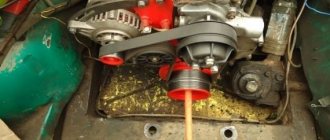
On Kalina cars, the generator is three-phase and produces alternating current. There is no need to go into too much theory; an ordinary motorist only needs to know how to independently diagnose and repair the installation. This means installing the generator and voltage regulator directly. The fact is that at the output of the power windings the voltage jumps in the range of 10-30 V, and to power the entire on-board network you need 12 V. The first step is to rectify the voltage and then stabilize it.
Checking an Individual Regulator
Checking the voltage regulator of the G-222 generator: 1 - battery; 2 - voltage regulator; 3 - control lamp.
As a rule, separate voltage regulators were installed on old cars, including domestic VAZs. But some manufacturers continue to do this to this day. The verification process is similar. To do this, you need to have a power supply with a voltage regulator, a 12 V light bulb, a multimeter and a directly tested regulator.
To check, you need to assemble the circuit shown in the figure. The process itself is similar to the one above. In normal condition (at a voltage of 12 V), the light bulb lights up. When the voltage value increases to 14.5 V, it goes out, and when it decreases, it lights up again. If during the process the lamp lights up or goes out at other values, it means that the regulator has failed.
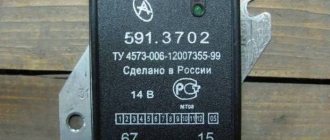
Checking relay type 591.3702-01
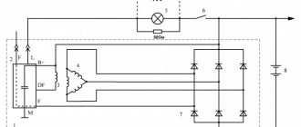
Relay test diagram type 591.3702-01
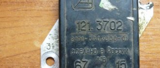
You can also still find a voltage regulator of type 591.3702-01, which was installed on rear-wheel drive VAZs (from VAZ 2101 to VAZ 2107), GAZ and Moskvich. The device is mounted separately and installed on the body. In general, the test is similar to that described above, but the differences are in the contacts used.
In particular, it has two main contacts - “67” and “15”. The first of them is a minus, and the second is a plus. Accordingly, to check it is necessary to assemble the circuit shown in the figure. The verification principle remains the same. In normal condition, at a voltage of 12 V, the light bulb lights up, and when the corresponding value increases to 14.5 V, it goes out. When the value returns to its original value, the light comes on again.
A classic regulator of this type is a device of the PP-380 brand, installed on VAZ 2101 and VAZ 2102 cars. We provide reference data regarding this regulator.
| Adjustable voltage at regulator and ambient temperature (50±3)° C, V: | |
| at the first stage | no more than 0.7 |
| on the second stage | 14,2 ± 0,3 |
| Resistance between plug “15” and ground, Ohm | 17,7 ± 2 |
| Resistance between plug “15” and plug “67” with open contacts, Ohm | 5,65 ± 0,3 |
| Air gap between armature and core, mm | 1,4 ± 0,07 |
| Distance between second stage contacts, mm | 0,45 ± 0,1 |
Testing a three-level relay
Regulated power supply
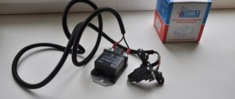
Some car owners install on their cars, instead of standard “chocolate bars,” three-level relays, which are technologically more advanced. Their difference is the presence of three voltage levels at which the battery power is cut off (for example, 13.7 V, 14.2 V and 14.7 V). The appropriate level can be set manually using a special regulator.
Such relays are more reliable and allow flexible adjustment of the cutoff voltage level. As for checking such a regulator, it is completely similar to the procedures described above. Just do not forget about the value that is set on the relay, and accordingly, check it with a multimeter.
Generator check
There is one method by which you can check the performance of a car generator equipped with a regulator relay 591.3702-01 with diagnostic elements. It is as follows:
- disconnect the wires that went to pins 67 and 15 of the voltage regulator;
- connect a light bulb to it (excluding the regulator from the circuit);
- Remove the wire from the positive terminal of the battery.
If, as a result of these actions, the engine does not stall, then we can say that the car’s generator is in order. Otherwise, it is faulty and needs to be checked and replaced.
Generator operating principle
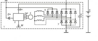
To visually visualize the operation of the installation, use the generator connection diagram. The second component of the installation is a voltage regulator, which is included in the power circuit of the rotor winding. The instrument panel contains a charge control lamp that:
- Lights up when the ignition is turned on and there is a breakdown in the generator set.
- Does not light up in normal mode and when there is a proper charge level.
A relay with normally closed contacts is used to power this lamp. Therefore, when the ignition is turned on, it lights up. Further, as soon as you start the engine, the generator begins to generate voltage. The relay winding is connected to the rotor power circuit; when voltage appears, the contacts switch - they open and the lamp goes out.
Causes and symptoms of malfunction
The regulator will need to be replaced if the part fails. This can happen for several reasons:
- Short circuit in the circuit , which led to its breakdown. This happens quite often, since the “relay” is a power source, and there is no fuse between it and the rotor.
- Brushing of brushes resulting from friction against the rotor .
You can find out about problems with the operation of the generator, in particular with the charging relay, by changing the voltage of the on-board network.
In practice, during the operation of the car this is determined by the following symptoms:
- Headlight beams of different brightness . When you press the gas pedal they light up brighter, at idle they dim.
- An undercharged battery will affect the morning start-up. The starter turns much harder than usual.
Battery overcharging due to increased voltage . It can affect you in several ways:
- Electrolyte boiling in jars . It will manifest itself as a sharp, unpleasant odor emanating from the battery;
- Frequently blown fuses . If they are missing, the “weakest” part of the wiring will burn out (places with pockets of copper oxidation, poor contacts).
Traces of electrolyte are visible along the edges of the battery. This occurs due to overcharging.
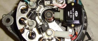
Main Generator Components
In general, a generator is a converter that creates electrical energy from mechanical energy. On all cars, the design and operating principle of these devices are similar. The design consists of the following components:
- The stator winding, a thick copper wire is used for it, since it is with its help that voltage is generated.
- The rotor winding is excitation. Without it, it is impossible for current to appear in the stator winding. In order for any potential difference to appear in the frame, the presence of two components is necessary - rotation and a magnetic field. Thanks to the generator belt on the Kalina, the rotor rotates. It is its winding that fulfills these two conditions - a magnetic field is created around it, and it rotates around its axis.
- The rotor is equipped with slip rings, to which voltage is supplied using a brush assembly.
- A pulley mounted on the rotor allows rotation to be transmitted from the crankshaft via the generator belt on the Kalina.
- A mechanical or electronic voltage regulator changes the voltage on the rotor winding. Due to this, the generator produces a stable voltage.
- The block of semiconductors (valves) mentioned earlier is necessary to convert three-phase alternating voltage into unipolar direct voltage.
- Covers with bearings are designed for rotor alignment and normal operation of the unit.
- The capacitor allows you to get rid of residual alternating current after rectification.
Installation and repair features
Installation occurs in reverse order. If necessary, the generator is replaced or repaired. In some cases, repair will be impractical, since there are many unusable components, including stator and rotor windings. Restoration will be expensive; it will be much easier to completely replace the generator on Kalina. The cost of a new generator in stores is 4-5 thousand rubles. At "showdown" you can buy it 2-3 times cheaper.
Welcome! Voltage regulator - it is installed on the generator and is directly connected to it, thanks to it, the entire current that the generator gives out changes and flows more evenly, for example, the more you turn the engine of a car (increase the speed, that is), the generator will work stronger and much more give out current, all this happens because the generator is connected to the engine (namely, it is connected to the crankshaft), but the voltage in the on-board network will also change from this (The more current the generator gives, the stronger this current increases in the entire on-board network car), therefore, when the speed increases, the light will constantly burn stronger, and when it decreases, it will dim because the current strength will decrease, so no matter what happened, a voltage regulator was invented, thanks to which the current strength in the on-board network always remains the same, but it changes when you turn on additional devices that need more current, that is, for example, you turn on the high beam headlights of a car and the current supply increases through the regulator so that there is enough power for these headlights, in addition, the current supply flowing through The regulator is constant and does not jump higher or lower, so the headlights work in the same mode and do not shine either stronger or weaker.
Note! In order to change or check the voltage regulator, you will need: Two different types of screwdrivers, as well as two wrenches that will be “12” in size, and you will also need a DC voltmeter thanks to which you can clearly determine what voltage you have in your on-board network and whether it is jumping, and among electrical appliances, a megohm meter is also useful, thanks to which you can check the regulator’s capacitor for serviceability, thanks to which the current strength remains constant when supplied to the on-board network!
Summary:
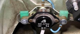
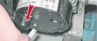
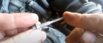
Where is the voltage regulator located? It is located on the generator itself, as was already said a little earlier, a plus wire and a wire block are also suitable for it, so that the regulator does not become dirty; for this purpose it is also closed with a plastic cover, in more detail the pin that comes out of the regulator you can look at photo which is located below, in this photo you can just see the same plastic cover that closes the regulator, and in the other photo (Small) you can see that the cover has already been removed and only one pin sticks out, which comes from the regulator (This pin is on both indicated by a red arrow in the pictures).
When should you change the voltage regulator? It needs to be changed when it begins to pass alternating current into the on-board network (Alternating current is the current that rises or falls under the condition that the circuit leaves its direction unchanged), in other words, if the current strength fluctuates (And this should not happen), then the regulator must be replaced, if the current fluctuates, for example, the headlights may burn either worse or more intensely (Depending on the engine speed, at high speeds the headlights will burn stronger), and the regulator must also be replaced if it begins to produce either less current than necessary (In this case, you will have an undercharge of the battery), or more (With a stronger current, you may burn out the main part of the wiring in the car that will not withstand the heavy load, or if you have fuses, then at best they will have time to open the circuit and nothing bad will happen to the wiring).
Signs of generator failure
To diagnose the generator set, it is not necessary to remove it. Here are some typical symptoms of breakdowns:
- The presence of a hum and whistle from the generator indicates that the bearings are damaged. If you start it, the rotor may jam and the belt may break.
- Whistling, short-term ignition of the charging control lamp - the alternator belt on the Lada Kalina is worn out, or it has low tension. If the lamp is constantly on, there may be a break.
- If the charging lamp is on, this means that there is no voltage at the generator output. The reason may lie in the windings, voltage regulator, slip rings, diodes, wiring.
Troubleshooting should begin from the simplest to the more complex. It is possible that the cause of the generator failure is a break in one wire. But it is quite possible that there is a break in the rotor or stator winding. When making repairs, the generator connection diagram should be at hand.
How to replace the voltage regulator and check its serviceability on a VAZ 1117-VAZ 1119?
Checking the voltage regulator for serviceability:
1) At the beginning of the operation, you will need to find where the generator itself is located and after you find it, move your hand to the side with the rubber cover indicated by the red arrow, this cover covers the “B+” terminal; in simpler words, this is the positive terminal and it comes from the generator to this terminal (By the way, it is also indicated by a blue arrow) you will need to connect the positive wire of the voltmeter and after connecting it, throw another wire (Minus wire) coming from the same voltmeter to ground (The places where you need to connect the wire , indicated by a green arrow), after the operation has been completed, a DC voltmeter will show you the voltage in the vehicle’s on-board network.
Actions when charging disappears
The generator on a Kalina with air conditioning has more power than on cars without an air conditioning system. The design and faults are the same. What to do if charging is lost? Don't panic and check immediately:
- Voltage regulator. The easiest and most expensive way is to replace it with a known good one. But you can also apply voltage of 12 V and 15 V to check operation. Regardless of whether the regulator is mechanical or electrical, it will behave the same. In the first case, voltage will be supplied to the excitation winding, but in the second - not.
- Alternator slip rings and brushes. You can use a simple lamp probe to check the contacts. The length of the brushes must be more than 5 mm, otherwise they should be replaced.
- The integrity of the field winding can be checked with a tester. Moreover, there is no need to remove the generator, just crawl up to the slip rings and check the resistance between them. Please note that they should not short to ground.
- The condition of the stator winding and diode bridge can be assessed only after dismantling the generator.
Checking the rectifier unit (diode bridge)
To perform this diagnostic, it is necessary to remove the diode bridge from the Kalina generator; this was described in more detail in previous articles in this section.
Then we connect the tester with the black wire to the negative plate of the block, and the red one in turn to the three contact terminals of the diodes. This way we check all the rectifiers in the block. The values on the device should be in the range from 400 to 800 Ohms. Personally, on my Kalina, during this test, all diodes showed a resistance within 535 Ohms. But the repair instructions from the Third Rome publishing house talk about numbers of 580-620 Ohms. I will say right away that when I rang two serviceable generators, the values specified in the manual were not achieved, although there were no problems with charging, so I personally doubt the accuracy of the data in this instruction.
How to dismantle the generator
Now we need to tell you how to remove the generator. To do this, proceed according to the following principle:
- Disconnect the battery.
- Disconnect all wires going to the generator.
- Pre-treat threaded connections with penetrating lubricant such as WD-40.
- Unscrew the nut from the top mounting of the generator. The bracket can also be removed.
- Unscrew the nut from the lower mounting bolt. Hold the bolt head from turning.
- Remove the Kalina generator belt from the roller. There is no need to perform any manipulations with the air conditioner and power steering.
- Remove the generator from its seat.
Checking and tensioning the generator drive belt
A loose belt and poor condition can be identified by a characteristic “whistle”, especially when starting the engine.
To perform the work, you can remove the right front wheel or install the car on an inspection ditch or overpass.
1. Remove the right side of the engine mudguard.
2. Visually check the condition of the generator drive belt. We apply a force of 98 N (10 kgf) to the belt exactly in the middle between the generator pulley and the engine crankshaft pulley. (You can use the steelyard).
3. To adjust, remove the windshield washer reservoir.
4. Using a 19-mm open-end wrench, unscrew the locknut of the tensioning mechanism.
By rotating the adjusting pin with a socket wrench by 8, we change the tension of the generator drive belt (clockwise we increase the belt tension, and counterclockwise we decrease it).
Excessive belt tension can lead to failure of the front alternator bearing.
5. Check the tension of the generator belt (see above) and, if necessary, repeat the adjustment.
6. After making sure that the belt is tensioned correctly, hold the adjusting pin and tighten the locknut.
7. Install the engine splash guard.
Disassembling the device
To disassemble the generator, you need to perform several simple manipulations:
- Remove the drive pulley. Try not to lose the key.
- Unscrew the nuts from the back cover that secure all parts of the structure.
- Remove the voltage regulator. At the same time, evaluate the condition of the brush assembly.
- Disconnect all parts of the generator.
After this, you can begin to carry out repairs.
Bearings often fail, especially the one located in the front cover. The reason for this is excessive belt tension. To make a replacement, you need to unscrew four screws and press the bearing out of its seat. Instead, install a new bearing. To increase reliability, change both rollers at once.
About the principle of operation of a car generator
The operation of the Lada Kalina generator unit is based on the following principle: an alternating current is induced in the stator winding, which is subsequently transformed into direct current through a rectifier module located on the body of the unit. The generator cover is also equipped with an electronic voltage regulator and a brush holder. The rotor of the device receives torque from the crankshaft pulley. The transmission link is a poly V-belt.
The basic characteristics of the generator set include the following parameters:
- maximum generated current – 85-90 Amperes;
- operating range of on-board voltage – 14.4-15.1 Volts;
- rotation ratio of the motor and rotor – 1:2.4;
- right-hand direction of rotation.
The housing of the unit is held together by pins that tighten the stator with the covers. The mounting sockets of the indicated covers contain bearings, which ensure the ability of the rotor to rotate. The rear bearing is installed inside the cover with a minimum gap. The front element is equipped with the ability to slide along the surface of the rotor shaft. It is fixed inside the front cover with a slight interference fit, and a pressure plate covers it from the outside. The back of the device is protected by a plastic casing.