As I said earlier, at the opening of the hunt a weak unit appeared in my SUV :( The most annoying thing is that it was almost out of the blue.
Due to a breakdown at the very beginning of the season, the NIV had to be restored in the shortest possible time
.
Therefore, the most rational option was no longer needed
- installing a steel RPM housing.
If it weren’t for the great desire to hunt
, then I
would have gone the route of installing a steel body
and unlinking the bridge.
However, we should not forget that if I had not had a passion for hunting, I would not have had a NIV at all
!
So, in their city of Novomichurinsk they couldn’t find a used front axle, so they had to go the route of installing the RPM in a new building
.
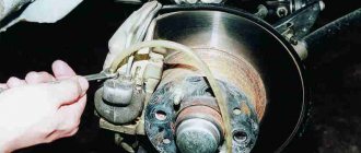
First of all, it was necessary to remove the old bridge
.
Fortunately,
has an inspection hole
in the garage
where the NIVA was parked .
Arriving at lunch on April 17th at the garage, I began to disassemble it, in 4 hours alone
I managed to unscrew everything to pull out the bridge.
But it’s very difficult to extract it alone, so a friend came to the rescue and together we quickly extracted the “patient”
.
The sequence for removing the bridge is as follows
: 0) drain the oil from the RPM; 1) unscrew the lower ball joints to move the steering knuckles to the side, do not forget to jack up the levers so that the spring does not tighten; 2) remove the axle shafts from the fists; 3) unscrew the CV joint from the bridge; 4) unscrew the bridge from the internal combustion engine; 5) use a chisel to mark how the cardan was screwed to the bridge; 6) jack up the bridge; 7) unscrew the front cardan from the axle; With the help of a partner, we pull out the bridge.
The next day, the search began for the necessary spare parts: RPM crankcase - 2121-2302015
- 1 PC.
— 3,020 rub.
Set of gaskets RPM -
2121-2301015/70/308
- 1 pc.
— 40 rub.
Studs
M12x1.25x30
- 2 pcs.
— 80 rub.
Studs
M6x12
- 8 pcs.
— 24 rub.
Studs
M8x20
- 3 pcs.
— 15 rub.
Studs
M8x25
- 3 pcs.
— 18 rub.
Breather -
2101-1700020
- 1 pc.
— 60 rub.
shank nut
M16x1.5
- 1 pc.
— 35 rub.
Spacer sleeve -
2101-2402029-01
- 1 pc.
— 140 rub.
Bearing -
2101-2402025
- 1 pc.
— 397 rub.
Bearing -
2101-2403036
- 2 pcs.
— 840 rub.
Shank oil seal -
2121-2302052
- 1 pc.
— 100 rub.
Flange mounting bolt -
2101-2201107
- 4 pcs.
— 20 rub.
M8
nut - 4 pcs.
— 24 rub.
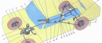
Niva drive device
The chassis of the car is made on the principle of permanent all-wheel drive - torque from the power unit is transmitted to all 4 wheels. This scheme improves the performance of the car when driving in off-road conditions, while simultaneously reducing the load on transmission parts.
The Chevrolet Niva drive consists of the following components:
- Gearbox.
- Transfer case.
- A pair of drive and cardan shafts.
- Front and rear axle gearboxes.
The transfer case is designed to distribute torque between the drive axles of the vehicle. The car is equipped with a two-speed transfer case, which provides:
- stable running of the machine when driving at low speed and at high engine speeds;
- power distribution between drive axles, depending on road grip.
The differential is one of the most important elements of the transmission. Its main purpose is to distribute traction force, and, if necessary, ensure rotation of two consumers at different angular speeds. The Chevrolet Niva drive transmission has three differentials:
- One for each axle (inter-wheel) - they allow the wheels of the same axle to rotate at different speeds.
- The third (interaxle action) - transmits power from the power unit to both axles of the vehicle. It also allows the shafts to operate at different angular speeds, depending on operating conditions, which significantly improves controllability.
A pair of cardan shafts (CV joint or cross design) provide connection between the transfer case and the drive axle gearboxes. Both car shafts have the same design - they are interchangeable.
The front and rear axles transmit force from the transfer case to the drive wheels through external and internal angular velocity joints.
There was a breakdown
The front axle (Niva) often requires replacement, the price of which sometimes reaches 20,000 rubles, for those people who are constantly trying to improve their car or reduce its consumption. The actions of amateurs lead to increased wear of one or another bridge, and sometimes both at once. However, the bridge does not always fail due to human intervention, because no one has canceled simple breakdowns and wear of parts.
It's okay if you've never seen the front axle, Niva will forgive you for that. The sound will immediately let you know about a breakdown - increased noise, squealing and squeaking will be difficult to miss. Another common problem is oil leakage, but this problem can easily be identified during a technical inspection. It is easy to understand that noise occurs when there is poor engagement, wear of bearings and gears, as well as physical damage to the bridge, which is extremely unlikely, but still possible. Oil leakage occurs due to poor assembly and wear of the seals. At the same time, non-man-made transmission breakdowns are an extremely rare occurrence, since the Chevrolet Niva and Niva 2121 are extremely reliable and simple.
The principle of operation of all-wheel drive on a Chevrolet Niva
In normal mode, the Chevrolet Niva operates in high gear with the differential unlocked. Torque is transmitted from the power unit, through the gearbox and intermediate shaft, to a two-stage transfer case gearbox. A center differential is installed in the transfer case housing. It links the front and rear axles, allowing them to rotate at different speeds, depending on road conditions and direction of travel.
How does all-wheel drive work on a Niva with a locked differential?
When all-wheel drive is engaged, both cardan shafts are secured with a locking clutch. This promotes uniform transmission of traction force to both axles of the vehicle. Due to this, the vehicle's cross-country ability increases, but controllability deteriorates.
Advice: It is not recommended to use the lock mode on roads with good grip, as this will lead to accelerated tire wear, increased load on transmission parts and components, and will also increase fuel consumption.
Transfer case alignment
Correct installation of the transfer case can be done in several ways. Most often in auto repair shops, repairmen use the following method:
- hang the car on a lift;
- loosen the transfer case;
- start the engine;
- engage the gear and accelerate the car according to the speedometer to the speed at which vibration occurs (often it occurs at speeds from 40 to 80 km/h);
- without using the brakes, reduce the engine speed, then turn off the ignition.
The transfer case itself is centered in place, all that remains is to tighten the fastenings of the supports.
You can also adjust the position of the RC using a wire; we do it as follows:
- loosen all four fastenings of the transfer case supports;
- fasten one end of the wire to the rubber coupling of the propeller shaft;
- we attach another piece of wire to the CV joint, bring the other ends of the wire to each other;
- rotate the shaft; if the transfer case is not centered, the ends of the wire will diverge during rotation;
- the task comes down to installing the transfer case using the selection method so that the ends of the wire practically do not diverge from each other in any position when turning the shaft.
Source
Differential
This mechanism is a kind of distributor of traction forces coming from the motor to the wheels. An important feature is that the latter have the ability to rotate at different speeds. The importance of having a differential mechanism is due to the fact that during turning maneuvers, the wheel located inside makes fewer revolutions when compared with the number of turns of the outer wheel.
In the absence of a differential mechanism, this would cause detrimental consequences, such as wear and damage, because the result would be the following: when turning, one wheel would be in a slip state, and the second would simply rub against the road surface. The design features of the Niva transmission provide for the presence of 3 differentials. They are located in each of the bridges and in the transfer mechanism.
When the car moves on a flat road and in a straight line with differentials, the traction force is divided equally between all 4 wheels. If there is insufficient adhesion of the wheels to the surface or slipping occurs, the differentials will redistribute the load on the slipping and sliding wheel so that the first receives more force, and the second, accordingly, less.
We have already mentioned UAZ. Despite many similarities, it should be understood that the VAZ’s all-wheel drive is made in the “pat-time” style. This means that when connected, the axes are firmly connected to each other, and rotation occurs at the same speeds. This device imposes some restrictions on the use of all-wheel drive - it can only be used in cases where road conditions allow slipping. In cases with hard asphalt roads and highways, it is recommended to switch the car to single-drive mode.
Possible damage
There can be many types of defects. There are enough parts inside the unit. Most often, gear teeth break off, bearings wear out, or cracks and nicks appear in the elements. All of them are subject to replacement. It is virtually impossible to repair such damage.
Gearboxes are one of the most vulnerable components of Nivas of all generations. The average cross-country ability before the first breakdown is 100 thousand km. Gearboxes are one of the most vulnerable components of Nivas of all generations. The average cross-country ability before the first breakdown is 100 thousand km.
Before starting repairs, it is necessary to identify the malfunction. The operation can be performed in three ways:
1. Eliminate extraneous sounds (road surface, traffic, etc.). Gradually accelerating, reach a speed of 90 km/h, then smoothly brake the engine. Record the nature of the noise, the moments of its appearance and disappearance. On a flat section of the highway, accelerate to 90 km/h, turn off the ignition by turning the key one notch. Continue coasting until you come to a complete stop. If the sound does not correspond to previous experience, failure of the differential bearings or drive gear, as well as gearbox gears, cannot be ruled out.
2. Put the car on the handbrake and start the engine. As you increase the speed, analyze the noise. Their coincidence with the first part of the previous test indicates the absence of obvious malfunctions in the gearbox.
3. To accurately localize the noise, lift the car. Spin the wheels using fourth gear.
A series of downshifts
You can often encounter the following type of misconception: switching the rear handle can increase the power characteristics of the motor. But this is not true. It serves to change the gear ratio between the engine and the wheels. By increasing it, the traction forces on the wheels will increase. There is also a reduction gear in the dispensing mechanism.
DON'T WASTE MONEY ON REPAINTING! Now you can remove any scratch from the body of your car in just 5 seconds.
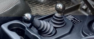
Its operation can be controlled using the rear handle. When we shift the lever back, we will have a gear ratio of 2.135 - this is a low gear. It is recommended to downshift such a gear only when the car is stationary and the clutch is depressed. Despite the fact that the manual does not contain such a restriction, novice and inexperienced Niva drivers are not recommended to switch while driving, since the Niva transfer mechanism is not equipped with a synchronizer.
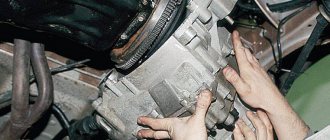
Disassembly
The gearboxes of both bridges have a similar design, which allows us to consider the disassembly process using the example of one of them. The element is first cleaned of dirt and fixed on the workbench. Remove the cover and gasket from the gear housing.
Unscrew the bearing nut locking plate. Mark the original position of the covers.
Remove the right bearing cap bolts using a 17mm wrench.
Then halve it and then remove the adjusting nut and bearing ring.
Repeat the procedure for the elements on the left. Remove the differential box with contents.
Remove the drive gear with accessories. Pull out the spacer sleeve.
Using a drift, remove the inner ring.
Unfasten the flange connection by inserting two bolts into the holes.
Use a screwdriver to pry off the oil seal of the drive gear.
Remove remaining parts.
Using a puller or chisel, disassemble the Niva differential 21214.
Remove the axle, side gears and support washers.
Tips for owners
To make driving your car comfortable, read some important points:
- The usual, standard arrangement of the front and rear handles is forward and backward, respectively. Movement in this mode can and should be carried out in areas characterized by even and smooth surfaces.
- Locking the differential by switching the front handle to the rear position is best on roads characterized by increased slipperiness. This measure will give Niva stability. It is worth understanding that after overcoming the problem area, the handle will need to be returned to its original position.
- As noted earlier, downshift should be activated before a potential obstacle, but not while the car is already stuck.
- It is worth understanding that activating the lock when the vehicle is stationary is sometimes impossible, even if the clutch is depressed. This may be caused by the clutch teeth hitting the gear teeth. In this case, you can try to activate the lock by starting to drive slowly and make a slight turn. If problems arise with disabling the lock, it is recommended to perform the same procedure with the clutch depressed and the steering wheel slightly rocked.
Procedure
Select the adjustment ring 5.
- Thickness is measured by B and G.
To do this, you need to use the formula d1=B – (111, 960 G), calculation accuracy 0.025 mm. Install the ring.
- Place the shaft into the front axle housing. It is necessary to check the torque of the shaft (1-2 N per cm).
- When installing the differential together with the driven gear, measure dimension E by pressing it with a force of 5000 N. The gear must be turned several revolutions so that the bearing is installed correctly. In the crankcase you need to measure size B. Using the actual dimensions B and E, and the installation size of 50 millimeters, select the adjusting ring using the expression d 2 = B - (E 50 X), d 2 - ring thickness, X = 50 mm.
- Place the differential in the housing and secure it.
- Adjust the bearings by tightening nut 23 while turning the differential to ensure the correct location of the rollers. Check the rotation torque of the gear. The clearance of the newly installed gear must be checked after adjustment operations with the indicator.
Special equipment: Neoliner NWX660 packer.
The test is carried out on several teeth. The difference in gaps is not allowed more than 0.05 mm. The nominal side clearance is 0.2 mm. If it is smaller, the ring is changed to a smaller thickness. When checking the size of the gap, there is no need to tighten the tension.
Dismantling and assembling the rear axle gearbox of Chevrolet Niva
Tools:
- Straight box spanner 10 mm
- Straight box spanner 17 mm
- Kern
- Small hammer
- Beard
- Driver for socket attachment
- Extension for socket wrench
- Knob attachment 10 mm
- Knob attachment 17 mm
- Bearing puller
- Soft metal drift
- Device made from an old drive gear
- Level
- Flat feeler gauge
- Torque wrench
- Mounting blade
- Dynamometer
- Pliers
- Calipers
- Vise
Parts and consumables:
- Strong thread
- Differential bearings
- Axle gears
- driven gear
- Pinion shaft
- Tapered pinion shaft bearing
- Spacer
- Cuff
- Flange nut
- Kerosene
- Rags
- Adjustment ring
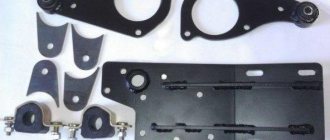
1. Having installed the gearbox on the workbench, use a 10mm wrench to unscrew the two bolts securing the locking plates of the differential bearing nuts and remove the plates.
2. Use a core to make marks on the bed and the corresponding bearing cover so that during assembly you can install the covers in their places.
3. Using a 17mm wrench, unscrew the bolts securing the bearing caps.
4. Remove the adjusting nuts from the differential housing.
5. Remove the outer rings of the bearings from the differential housing. If we do not change the bearings, then we mark the outer rings so as not to mix them up during installation, because The bearings are individually worn in and it is not advisable to disassemble them.
6. We check the absence of radial play in the axle gears.
7. Use a puller to compress the inner rings of the bearings.
8. Using a 17mm wrench, unscrew the eight bolts securing the driven gear to the differential housing and remove it.
9. Using a beard, knock out the satellite axis.
10. Turn the axle gears and remove the satellite gears.
11. We take out the axle gears with adjusting washers, marking their position.
12. Remove the drive gear and the deformed spacer from the crankcase. When assembling the gearbox, replace the bushing with a new one.
13. Use a soft metal drift to knock the inner ring of the tapered bearing off the drive gear shaft.
14. An adjusting ring is installed under the bearing to ensure the correct relative position of the main gear gears.
15. Use a suitable tool to knock out the outer rings of the tapered bearings from the crankcase.
16. We thoroughly wash the gearbox parts in kerosene and carefully inspect them. If at least one tooth is damaged (chipping, waves, scratches, scuffs on the working surfaces), we replace the gears with new ones.
The edges between the tops and working surfaces of the driven gear teeth must be sharp. If the slightest nicks or roundings are visible, replace the main pair with a new one.
Minor damage to the satellite axle, axle pinion journals and their mounting holes can be eliminated with fine sandpaper followed by polishing. When assembling, replace the cuff, flange nut and spacer with new ones.
17. If the gearbox is assembled in the same crankcase, then the change in the thickness of the drive gear adjusting ring can be calculated as the difference in the deviations in the sizes of the old and new gears. The deviation in size with a “+” or “–” sign in hundredths of a millimeter is engraved on the drive gear shaft.
For example, the old gear is engraved with –12, and the new gear is 4. The difference between the two corrections will be 4–(–12)=16. This means that the new adjusting ring should be 0.16 mm thinner than the old one. With the opposite ratio of corrections (4 on the old one, and 12 on the new one), the ring should be 0.16 mm thicker than the old one. To more accurately determine the thickness of the adjusting ring, we make a device from the old drive gear.
18. We weld a plate 80 mm long and trim it to a size of 50–0.02 mm relative to the plane for the bearing. The serial number and size deviation are engraved on the conical part of the shaft.
Source
How to change?
If the mechanism is seriously damaged, it makes sense to replace it with a new one. To do this you will need a new gearbox and a small set of tools:
- wheel wrench;
- jack (if the work is done in an inspection hole);
- chisel:
- hammer;
- hex wrench 12;
- ring or open-end wrenches for 13, 17 and 27;
- syringe for filling transmission oil;
- container for processing.
Important: replacement or repair of the gearbox cannot be performed without a lift, inspection ditch or overpass.
Operating procedure
- Place a waste container under the gearbox.
- Unscrew the drain plug, then the filler plug.
- Wait until the entire transmission flows out of the gearbox.
- Unscrew and remove the front wheels.
- Unscrew the cardan shaft from the flange on the shank.
- Undocking and hanging the cardan.
- Unscrew the fastening of the right cover from the suspension cross member.
- Unscrew the fastening nuts and disconnect the shock absorbers from the front control arms.
- Unscrew the threaded connections holding the wheel drive bearing caps.
- Unscrew the nuts securing the brackets holding the gearbox.
- Unscrew the nut securing the left gearbox cover to the cross member.
- Remove the hub cap and unscrew the right wheel hub nut.
- Remove the centering sleeve.
- Compress the suspension spring and unscrew the ball joints.
- Move the steering knuckle to the side.
- Disconnect the exhaust pipe from the exhaust manifold.
- Pull the gearbox back.
- Remove the right wheel drive.
- Remove the gearbox from the machine
To install the new unit in place, you must perform the operations in reverse order.
Important: after installing the gearbox, do not forget to fill it with transmission oil. Otherwise, you will soon have to change it again with another one
Repair
It is not necessary to buy a new unit. You can replace the oil seals or gears yourself, and then adjust the mechanism. It makes sense to repair the mechanism if most of the parts are not worn out. Otherwise, it’s worth overpaying and installing a unit that is known to work, so as not to return to repairs.
To repair and adjust the front axle gearbox you will need:
- mark;
- hammer;
- spanners for 10 and 17;
- knob with extension;
- end attachments at 10, 17,19;
- punch;
- bearing puller;
- mounting blade;
- caliper;
- pliers;
- dynamometer;
- flat probe;
- level;
- vice.
You will also need new gaskets for the covers.
Adjustment
It will not be possible to adjust the drive gear without a torque wrench and mandrel A.70184 . You will also need:
- level;
- calipers;
- flat feelers for measuring gaps;
- adjusting rings with a pitch of 0.05 mm;
- perfectly straight metal rod.
The drive gear is adjusted as follows:
- Align the crankcase mating plane horizontally (you will need a level);
- Install a metal rod onto the bearing bed.
- Place the adjusting rings and measure the distance from the rod to the mandrel.
- Install the adjusting ring. Its thickness is calculated as the difference between the actual clearance and the deflection value indicated on the new gear.
- Install the shaft and related parts in place, secure the drive gear flange.
- Using a torque wrench, tighten the nut with a force of 12 kgf.
- Using a dynamometer, check the moment at which the drive gear shaft begins to rotate. If this value does not correspond to 7.6 to 9.5 kgf, the nut needs to be tightened.
Important: the tightening torque should not exceed 26 kgf. If it is not enough, the spacer sleeve must be replaced.
Adjusting the gap between the parts of the main pair is carried out in several stages:
- Tighten the nut located on the driven gear side to completely eliminate the gap.
- Using a caliper, measure the distance between both covers.
- Tighten the second nut.
- Check the distance between the two covers. It should grow by 0.1 mm.
- By rotating the first nut, achieve a gap between the gears in the range of 0.08-0.13.
All that remains is to turn the gear while checking the clearance. If it remains unchanged, the adjustment is complete. A decrease or increase in backlash during gear rotation indicates deformation of the differential housing. You can try to trim it on a lathe, but it is better to replace it with a new one.