Print this article Font size 16
The differences between the ignition systems with injection and carburetor engines on the VAZ 2109 are quite significant.
On carburetor versions, the coil and distributor are responsible for ignition distribution. On injectors, this role is assigned to a special ignition module. It includes a pair of coils and control electronics.
How does the SZ work?
Another important difference between the carburetor and injection ignition systems (SZ) is the absence of the need for settings on the electronic type, setting the ignition timing, or adjusting the gaps. The sensors are responsible for distributing the ignition among the cylinders.
Classification of ignition systems
According to their type, ignition systems are divided into:
- Contact;
- Contactless;
- Contact transistor.
All of the listed ignition systems receive electricity from the battery or generator and are the most common.
Based on their characteristics, they are divided into:
- Inductive - electricity is concentrated in a magnetic field;
- Capacitive - electrical energy is collected in an electric field.
The difference here is where exactly the electricity is accumulated and then released to the spark plugs.
Contact SZ
The ignition power in this system comes from the battery or generator (mostly) - this is a classic.
However, the contact SZ, over time, during operation, ceased to be reliable.
The reason for this was the emergence of more modern engines, which began to operate under different load conditions, with different fuel mixtures and had a larger number of cylinders.
Therefore, in the mid-60s of the last century, the contact ignition system completely outlived its usefulness and was replaced by a contact-transistor SZ.
Injection motor
Injectors differ from the internal combustion engines described above in the presence of many electronic devices. In the case of an injector, failures are usually related to the operation of the sensors or the wiring itself.
To accurately identify the cause of an injector failure, you must perform the following steps:
- first disconnect the cable from the sensor;
- then, using an ohmmeter, measure the resistance level;
- After this, the received data will need to be checked with that indicated in the table in the car’s operating instructions.
Contact-transistor ignition system
It is an intermediate link between the contact - classic SZ and modern electronic ignition.
We will not delve into the weeds of the operating principle of this ignition system; for many, this information will be boring and uninteresting.
I would just like to note that in the contact-transistor system you will no longer find the capacitor familiar to the classical SZ, since due to the low current strength of 0.5A, it is no longer necessary (sparks are not formed when the contacts are opened or closed).
It is also worth noting that with a classic SZ installed, every 10 thousand km it is necessary to clean the contacts and it will serve you in the end from 35 to 45 thousand km of the car.
With a contact-transistor SZ installed, these indicators increase significantly, the service life of the ignition system has increased to 100 thousand km of vehicle mileage, and it does not require cleaning the contacts.
This is achieved through a built-in switch, which is not present in the classical system, the operating principle of which makes no sense to consider now.
But still there are problems here, which are expressed in the following disadvantages:
- The intermittent mechanism requires periodic adjustments to the contact gaps, since incorrectly set gaps affect the ignition timing;
- Contacts are constantly dirty and oxidized, so they require periodic cleaning;
- The possibility of the occurrence of resonance phenomena led to the establishment of restrictions on the maximum value of the engine operating frequency. As a rule, for a 4-cylinder engine this figure is no more than 6 thousand rpm.
Car modifications
VAZ-2108. The base model of the car, it was equipped with a 1.3-liter carburetor engine, was equipped with both a 4- and 5-speed gearbox.
VAZ-21081. Modification of a car with a derated 1.1 liter engine and a 4-speed gearbox.
VAZ-21083. Modification of a car with a 1.5 liter carburetor engine. This car was equipped with a 5-speed gearbox.
VAZ-21083-00. A modification of the VAZ-21083 car as standard, an index of this length began to be assigned in 2001.
VAZ-21083-01. Modification of the VAZ-21083 car in the “norm” configuration.
VAZ-21083-02. Modification of the VAZ-21083 car in the “luxury” configuration.
VAZ-21083-20. Modification of the VAZ-21083, but with an injection 1.5 liter engine. The car was equipped with a 5-speed gearbox.
VAZ-21083-21. Like the previous model, but in the “norm” configuration.
VAZ-21083-22. Modification of the VAZ-21083 car with an injection engine and a 5-speed gearbox in the “luxury” configuration.
VAZ-21083-37. A sports model with a 1.5-liter fuel-injected engine and a 5-speed gearbox. Designed for participation in the NGS "Lada Cup"
VAZ-210834 “Tarzan”. A prototype of an all-wheel drive SUV, developed in 1998 based on model 21083. The car was made as follows: on the frame of the VAZ-21213 Niva, on which the suspension, steering, engine, gearbox and transfer case were already installed, the body from the VAZ-21083 was installed . The junctions between the frame and the body were covered with plastic covers that look like thresholds. The wheel arches were also enlarged, on which linings were installed, and the bumpers were changed.
VAZ-21084. Pilot production batch of cars with a larger 1.6-liter engine. It was a VAZ-21083 engine, but with a block increased in height by 1.2 millimeters, in which the head was slightly modified and a new crankshaft and camshafts were installed. The piston was also modified, the new pistons were cut by 1.8 millimeters in height, and their diameter was 82 millimeters.
VAZ-21085. Modification with an injection 16-valve engine from a VAZ-2112 with a volume of 1500 cm3 and a power of 92 horsepower. The car was equipped with a 5-speed gearbox.
VAZ-21086. Export VAZ-2108 with right-hand drive for countries with left-hand traffic.
VAZ-21087. Export deformed modification of the VAZ-21081 for countries with left-hand traffic.
VAZ-21088. Export modification of the VAZ-21083 model with right-hand drive.
VAZ-2108-91. A modified V8 with a two-section VAZ-415 rotary piston engine, 1.3 liters and 140 horsepower.
VAZ-2108 X. The development of this modification began in 1985 by order of Aeroflot. A total of 10 cars were produced, which were designed to measure runway friction coefficient. Based on the information received, the braking distance of aircraft is predicted, and in the case of a wet runway, the speed at which aquaplaning begins. The dispatcher transmits the data from these measurements on board the landing aircraft.
Contactless - transistor ignition system (BTIS)
Now we have come close to the ignition system of the VAZ 2109. This VAZ car model is equipped with a non-contact ignition system, which has been used since the mid-80s.
In this system, the chopper mechanism has been replaced by a more modern non-contact sensor, which instantly and accurately determines the engine speed and angle of rotation.
Unlike earlier ignition systems, where their operation was based on the mechanical action of parts with each other, the principle of operation of the new ignition system is based on an electrical impulse, which is generated using a non-contact sensor. But first things first.
Good to know - How to set the ignition on a VAZ 2109 with a carburetor and injection engine with your own hands.
Features of work
The Samara Baltic car body and power unit serve well for many years, which cannot be said about the electrical part of the car.
But there are objective reasons for this:
- Harsh climatic conditions;
- Frequent loads during urban operation;
- Natural aging of insulation and materials.
Accordingly, owners are forced to quickly solve all sorts of problems and failures, and there are several ways to do this:
- Contact a branded service;
- Conduct diagnostics and repairs yourself.
Conclusions: we hope that we have clarified the situation regarding the features of the Samara Baltic model, which still remains the standard of quality and style for the domestic automobile industry. And its lucky owners will continue to operate the car without breakdowns or failures of electronic systems.
Brief acquaintance - advantages
As noted above, the ignition system of the VAZ 2109 is non-contact transistor.
During its existence, this SZ has proven itself to be quite reliable, despite the fact that it produces high energy up to 50 J, and the breakdown voltage in it can reach 30 kV or more. The operating efficiency of a contactless transistor SZ is considered very high.
Advantages of this SZ:
- If the operation of the SZ is provided with a Hall sensor, then the spark energy indicator is not affected in any way by either the engine operating frequency or the voltage indicator in the vehicle’s electrical network. This happens because the time period of energy concentration in the ignition coil always remains unchanged, which is one of the reasons for the high efficiency of this ignition system;
- Since there is no direct mechanical interaction between the contacts, this means they do not burn or become dirty, and of course there is no need to clean them;
- There is no need to adjust the position of the contacts, for one reason, they simply do not exist;
- Since the mechanical impact of parts on each other in this system is minimized, this means that phenomena such as rotor vibration, resonance phenomena, and uneven spark distribution across the spark plugs are completely absent;
- Thanks to the constant increased energy in the spark plug, which can reach 50 J, ignition of the fuel mixture in the cylinders occurs without failure. This is especially felt during car acceleration, when everything happens smoothly, steadily and without jerks;
- Fuel economy has increased by approximately 5% and CO emissions have been reduced by 20–25%;
- In cold weather, starting a cold engine, even with a battery discharged to 6V, is more stable than with other ignition systems.
BTSZ device
The ignition system of the VAZ 2109 consists of:
- Switch 3620.3734;
- Spark plugs A17DVR;
- Distributor sensor 40.3706;
- Ignition coils 27.3705;
- Ignition switch;
- — A locking device that prevents the starter from being turned on again until the ignition is completely turned off;
- — Locking and anti-theft device.
Design features and operating principle:
- The operating principle of the VAZ 2109 ignition system is based on the Hall effect.
- The sensor-distributor shaft receives torque from the engine camshaft and is located horizontally.
- Spontaneous shutdown of the ignition system occurs 2-8 seconds after turning the ignition key to the extreme left position and the engine is turned off.
- During the operation of the SZ, the switched current is equalized in the case when the voltage in the network varies from 6 to 18 V.
- At low engine operating frequencies, thanks to a special system built into the switch, the time of accumulation of electricity in the ignition coil is regulated, and the current is limited.
The ignition system of the VAZ 2109 operates at a voltage of up to 26 kilovolts, the duration of the spark discharge varies in the range of 1.6-2.0 ms and during this time 35 - 50 MJ of energy is released.
Distributor.
Sensor-distributor.
Comprises:
- There are two types of ignition timing regulators - vacuum and centrifugal;
- A voltage pulse sensor that regulates the operation of the switch.
Table 9-4. Purpose of plugs in the MC 2713-02 controller connector
| Plug no. | Plug purpose |
| 1 | EPHH valve control signal output |
| 2 | Supply voltage supply, +12 V |
| 3 | Output to the SZ signal switch |
| 4 | Output to VK signal switch |
| 5 | NO output for diagnostics |
| 6 | Input from carburetor limit switch |
| 7 | UI output for diagnostics |
| 8 | Input H01 for signal from NO sensor |
| 9 | UI input 1 for signal from the UI sensor |
| 10 | Total (weight) |
| 13 | Diagnostic output |
| 15 | Input for signal from temperature sensor (common) |
| 16 | Input for signal from temperature sensor |
| 18 | UI2 input for signal from the UI sensor |
| 19 | Input H02 for signal from NO sensor |
The “Channel Select” signal, or VC (II, in Fig. 9-16, a), has an angular pulse duration of 180° along the crankshaft. The moment of sparking corresponds in cylinders I and IV to the transition from a low signal level to a high one, and in cylinders II and III - from a high level to a low one.
The “Start of reference” signal, or BUT (III, in Fig. 9-16, a), is generated once per revolution of the crankshaft. The transition from low to high level corresponds to the position of the pistons of cylinders I and IV at TDC.
The “Angular impulse” signal, or UI (IV, in Fig. 9-16, a), is generated 128 times (according to the number of teeth on the flywheel rim) per revolution of the crankshaft. Therefore, the period of the UI signal is 2.8° along the crankshaft.
All controller outputs are designed as an “open collector” transistor of an npn structure with a load capacity of no more than 10 mA.
The purpose of the plugs in the controller connector is given in table. 9-4.
The switch is two-channel, type 42. 3734. Based on the control pulses (SZ and VK) of the controller, it produces:
— alternate switching on of channels and, consequently, ignition coils;
— formation of current pulses during the time tн (Fig. 9-16, b) accumulation in the primary windings of the ignition coils;
— the amplitude of the current pulses I— (see oscillogram V in Fig. 9-16, b) is equal to 8-10 A, and the accumulation time to in the crankshaft speed range from 750 to 4500 min1 and with a supply voltage of 14 V should be 9 -4 ms. The amplitude of the voltage pulses U— (see oscillogram VII) on the output transistors of the switch at the moment of interruption of the primary current (I—) is 350-400 V.
The purpose of the output plugs in the switch connector is given in Table. 9-5.
Sparking moment
Spark formation in the ignition system of the VAZ 2109 occurs as follows:
- The rotating ignition distributor shaft simultaneously rotates the screen with slots, which has the shape of a cylinder, and part of its inner surface consists of metal. By rotating, this screen forms an electromagnetic field.
- The highest sensor signal is generated when a metal part of the screen appears in the microswitch gap, and the smallest sensor signal is formed when there is no metal part of the screen in the working gap.
- The moment of signal level changes from higher to lower lasts only from 1 to 5 micro seconds and at this time sparking occurs.
Of course, the sparking process is more complicated and largely depends on the geometry of the screen slits, but there is no point in describing complex physical processes here, since they will not be clear to many people.
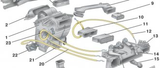
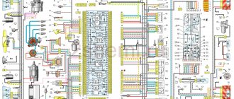
VAZ 2109 Electrical diagram
Electrical diagram of the VAZ-2108 VAZ-2109 car
1
.
Block headlight (headlight combined with a front light); 2
.
Geared motors for headlight cleaners; 3
.
Temperature indicator sensor; 4
.
Engine compartment lamp switch; 5
.
Sound signal; 6
.
Reversing light switch; 7.
Electric fan motor;
8
.
Fan motor sensor; 9
.
Headlight washer valve; 10
.
Generator; eleven
.
Rear window washer valve; 12
.
Windshield washer valve; 13
.
Window washer motor; 14
.
Engine compartment lamp; 15
.
Ignition circuits; 16
.
Portable lamp plug socket; 17
.
Oil pressure warning light sensor; 18
.
Ignition distributor sensor; 19
.
Carburetor solenoid valve; 20
.
Limit switch in the carburetor: 21
.
Switch; 22
.
Ignition coil; 23
.
Diagnostic block; 24
.
V.m.t. sensor; 25
.
Rechargeable battery; 26
.
Brake fluid level sensor; 27
.
Starter; 28
.
Carburetor valve control unit; 29
.
Additional starter activation relay; thirty
.
Windshield wiper motor; 31
.
Illumination lamp for the heater control panel; 32
.
Heater fan electric motor; 33
.
Additional resistor; 34
.
Heater motor switch; 35
.
Cigarette lighter; 36
.
Glove compartment lamp; 37
.
Assembly block; 38
.
Instrument cluster; 39
.
Brake light switch; 41
.
Parking brake warning lamp switch; 42
.
Carburetor choke warning lamp switch; 43
.
Instrument lighting switch; 44
.
External lighting switch; 45
.
Hazard switch; 46
.
Rear fog light switch: 47
.
Rear window heating switch; 48
.
Side direction indicators; 49
.
Light switches in the front door pillars: 50
.
Lamp switches in the rear door pillars (for VAZ-2109); 51
.
Interior lighting; 52
.
Ignition switch; 53
.
Wiper and washer switch; 54
.
Horn switch; 55
.
Switch for direction indicators, parking lights and headlights; 56.
Rear lights;
57
.
Fuel level indicator sensor; 58
.
Rear window heating element; 59
.
License plate lights; 60
.
Rear window wiper motor. A
.
Wire lug for connecting to the brake pad wear sensor; IN
.
Plug connector for connecting to the lamp for individual interior lighting; I.
_
Conventional numbers of plugs in the mounting block blocks; II
.
Numbering of plugs in the motor reductor block; III
.
Conventional numbers of plugs in the block and contacts of the ignition switch; K1
.
Rear window washer timing relay: K2
.
Relay-breaker for direction indicators and hazard warning lights; KZ
.
Windshield wiper relay; K4
.
Contact jumpers at the installation site of the lamp health monitoring relay; K5
.
Headlight high beam relay; KB
.
Headlight cleaner activation relay; K7
.
Window lift relay (not installed): K8
.
Horn relay; K9
.
Fan motor relay; K10
.
Heated rear window relay; K11
. Relay for low beam headlights.
This is interesting: What happens if you spray deodorant and smoke in the car?
Rice. 1.
Diagram of the contactless ignition system for VAZ 2108, VAZ 2109, VAZ 21099
8 - ignition switch
Rice. 2
Carburetor solenoid valve control system on VAZ 2108, VAZ 2109, VAZ 21099 cars
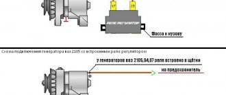
Rice. 3.
Connection diagram of the generator VAZ 2108, VAZ 2109, VAZ 21099
Rice. 5.
Starter connection diagram for VAZ 2108, VAZ 2109, VAZ 21099
SZ maintenance procedure
The ignition system of the VAZ 2109, like other components and assemblies of the car, must be periodically serviced.
Late maintenance can lead to:
- Loss of reliability of the ignition system, as a rule, this is manifested in frequent malfunctions in its operation;
- Reduction of technical indicators in operation;
- A sharp increase in fuel consumption;
- Failure to detect failures of SZ parts at the initial stage can lead to more serious malfunctions.
Maintenance must be carried out continuously at the intervals specified in the technical documentation for the vehicle.
Since the ignition system on a VAZ 2109 car includes a sufficient number of various electronics and during its operation a very high voltage is generated in it, for safety reasons and to eliminate the possibility of damage to important electronic parts, compliance with the rules listed below is mandatory:
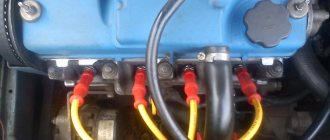
- When the engine is running, do not touch the ignition coil, switch housing, or wires transmitting high voltage with your hands;
- It is prohibited to test the functionality of the entire ignition circuit using the “spark” method, as this can lead not only to injury, but also to breakdown of the entire ignition system.
- It is forbidden to start the car using the spark gap method between the central terminal of the distributor sensor and the high-voltage wire.
Maintenance work is not complicated and includes:
- Cleaning spark plugs from carbon deposits or replacing them;
- Checking the insulation of wires and their fastening;
- Control of ignition timing and its correct installation;
- Cleaning all sides of the rotor cover and distributor sensor from dirt;
- Cleaning the current spacer plate of the rotor and the electrodes of the side terminals;
- Check the fastening of all parts of the ignition system, pay attention to the protective caps, and prevent the formation of cracks in them;
- Check the fastening of all types of wires, do not allow them to dangle.
Practical advice
The operation of an injection power unit, and in particular the maintenance of its electronic components, is fundamentally different from carburetor engine systems.
Owners of converted cars must learn a few basic rules:
Before dismantling the injection control system components, be sure to disconnect the negative cable from the battery terminal;
Working with car wiring requires care and precision.
- Do not start the engine if the terminals of the wires on the battery have poor contact. Be sure to check how tightly they are tightened;
- Do not disconnect the battery while the vehicle engine is running. This is guaranteed to lead to failure of the ECU;
- Monitor the ECU temperature. It is not allowed to overheat (65°C when the car is running and above 80°C, for example when drying in a paint booth). If such a process is unavoidable, remove the ECU from the vehicle for the duration of the work;
- It is also necessary to remove the ECU or disconnect it from the vehicle’s on-board system when carrying out welding work on body parts.
Checking the ignition system
Ignition installation.
Turning to the theory, we can recall that the ignition of the fuel mixture in the engine cylinder occurs due to a spark from the spark plug.
However, it should be understood that sparking must occur at a certain moment, at a certain position of the piston relative to top dead center.
In order to maintain the required operating parameters of the ignition system, there is such a thing as setting the ignition timing.
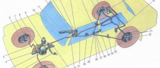
To perform such work, the VAZ 2109 has a scale specially placed in the clutch housing hatch, and there is a mark on the flywheel.
When shifted by one scale division, the crankshaft rotates by 1 degree.
The scale of the crankcase hatch has the longest mark, which is located in the middle. To set the 1st and 4th cylinders of the engine to TDC (top dead center), you need to align this long mark with the mark on the flywheel.
Standard indicators in the screenshot.
Note to Nine owners - VAZ 2109 wiring diagram
Car owners of domestic cars often encounter electrical wiring faults, which can lead not only to the inoperability of certain systems, but also to the impossibility of movement in general. To prevent this, owners of “nines” need to know what the VAZ 2109 electrical circuit is and what symptoms indicate its malfunction.
Using a strobe to check ignition
The most acceptable way to check the ignition on a VAZ 2109 is to use a strobe light.
Although the name of this device confuses some drivers, there is nothing complicated in its operation.
To check you need:
- Connect the wires “+” to “+” and “-” to “–” of the strobe light with the battery, and connect the wire of the device sensor to the high voltage wire suitable for the first cylinder.
- We start the car, with the engine idling, we direct the flashing beam of light emanating from the strobe into the clutch housing hatch.
- The ignition timing is set correctly if the mark on the clutch housing coincides with the mark on the flywheel, which corresponds to the initial ignition timing.
To change the ignition timing angle (IAF), you must:
- Position yourself so as to look at the sensor-distributor cover;
- To increase the SOP, turn the housing of the sensor-distributor clockwise;
- To reduce the OZ - counterclockwise.
Ignition distributor sensor
The VAZ 2109 ignition distributor has a dual purpose:
- Redirection of spark generation through the engine cylinders;
- Determine the correct moment of sparking depending on the load on the engine and the rotation speed of the crankshaft.
Redirection of spark generation through the cylinders occurs thanks to the rotor and the distributor cap itself.
The outer and central contacts are fixed on the cover, between which there is a resistor with a resistance of 5-6 kOhm.
Voltage is supplied from the ignition coil to the rotor through the central contact using a special carbon electrode.
During rotation of the rotor, current pulses with a certain frequency are supplied through an external contact to the side electrodes, which are located in the ignition distributor cover.
From the side electrodes, pulsed voltage is supplied through high-voltage wires directly to the spark plugs.
It is worth paying attention that the carbon electrode must move freely in the lid. If it jams, it will soon burn out. Therefore, it is necessary to monitor the wear of the contact carbon and not allow it to reach more than 0.5 mm.
For the VAZ-2109 ignition system, special blue high-voltage wires are used, which are characterized by a high breakdown voltage of 30 kV.
Many have heard of such concepts as earlier and later ignition.
Earlier ignition occurs when the ignition timing angle (IAF) is greater than the standard and sparking occurs much earlier than the piston has approached top dead center.
Late ignition is characterized by the fact that the spark appears later, when the piston has either reached TDC or has already passed it. Those. The OZ is much less than the normative value.
Depending on the speed of rotation of the crankshaft and the load on the engine, the ignition timing should be different and be adjusted literally on the fly.
A centrifugal regulator is provided for this purpose.
The maximum ignition timing varies from 30 to 40 degrees in accordance with the engine crankshaft rotation angle.
If you remember even a little of the school physics curriculum, you should know such a concept as centrifugal forces. This physical phenomenon forms the basis of the principle of operation of the centrifugal regulator.
When rotating, under the influence of centrifugal forces, the weights that are installed in the regulator move away from each other and rotate the rotor further along the rotation of the main roller.
The springs shown in the figure specifically have different stiffnesses, thereby achieving the desired ignition timing angles at a certain engine operating frequency.
A little history
The following basic systems are known that ensure the ignition of gasoline vapors in the internal combustion engine of a car:
- contact;
- contactless;
- microprocessor ignition system (MPI).
- Contact. Historically, this was the first attempt, it was quite successful and worked for many years. The diagram of such a system is shown below. The principle of operation of the device is simple - opening the contacts of the breaker breaks the primary circuit, which is why high voltage is induced in the secondary winding of the bobbin, which is directed by the distributor to one of the spark plugs. It was a simple, proven product, of course with its shortcomings, which were eliminated as technology and elemental base developed.
- Contactless. The operating principle is basically the same as the previous one, but the product is more reliable. In it, the contact mechanical breaker is replaced by electronic devices - a switch and a sensor. The diagram of such a product is shown in the figure.
- A microprocessor system that does not contain mechanical components and is built entirely on electronic components. The principle of operation also remains unchanged, the functional diagram of such a device is shown in the figure.
Vacuum regulator
The vacuum regulator, depending on how much the throttle valve is open and the load on the engine has increased, changes the angle of rotation, the maximum value of which for the VAZ 2109 should be in the range from 20 to 24 degrees according to the angle of rotation of the engine crankshaft.
Principle of operation:
- When the engine load increases and the gas pedal is pressed, the throttle valve opens;
- There is a decrease in vacuum in one of the compartments of the vacuum regulator;
- Reducing the vacuum in the chamber leads to movement of the spring-loaded rod;
- The moving rod pulls the plate along with it and rotates the breaker as the rotor rotates, thereby setting a smaller ignition timing angle.
- When the load decreases, the throttle valve closes, the vacuum in the chamber increases and the process occurs in the opposite direction.
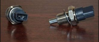
Spark plugs
The VAZ-2109 ignition system uses spark plugs A17DVR, A17DVRM where:
The importance of spark plugs in the overall operation of a car's ignition system cannot be underestimated.
It’s not for nothing that many drivers, out of habit that remains from past times, carry a spare set of spark plugs with them. This may be unnecessary, since modern candles are quite reliable, but breaking any habit is not so easy, even this one.
Read here what to carry in your trunk...
During operation, the spark plug endures huge ranges of loads, which are expressed in high operating temperatures, mechanical, electrical and chemical influences.
For example, in the combustion chamber, the operating temperature can vary from 60 to 2800 degrees, pressure up to 10 MPa, voltage up to 30 kV, not to mention the constant chemical effect on the spark plug from combustion products.
During the operation of the spark plug, carbon deposits form in all its areas, which leads to loss of current, and the gap between the contacts in the spark plug can increase from 0.012 to 0.016 mm or more for every 1000 km of travel.
Using the spark plug, you can simply diagnose the condition of the engine, but as a rule, we pay attention to the spark plugs only when malfunctions begin in the engine or when it’s time for scheduled maintenance.
The engine is in good condition if:
- No phlegm on the threads;
- A thin layer of soot on a dark rim;
- All electrodes are light grey, light brown, whitish or light yellow.
Signs of engine problems:
- There are oil or gasoline residues on the threads;
- There is loose black carbon deposits with spots on the rim;
- All electrodes are dark brown with spots;
- The candle is wet with dark soot;
- A dark rim on the outer part of the candle (if the candle is not sealed).
The use of only spark plugs of the A17DVR, A17DVRM brands in the ignition system of the VAZ 2109 is not a panacea, of course there are alternative options, but you need to be able to choose the right spark plugs for your car, and for this you should familiarize yourself with these concepts:
- What are hot and cold spark plugs and what engines are they used on?
- What is heat number;
- What is the compression ratio and a number of other indicators.
Therefore, if you do not understand these issues, then before replacing the spark plugs recommended by the manufacturer with others, seek recommendations from specialists.
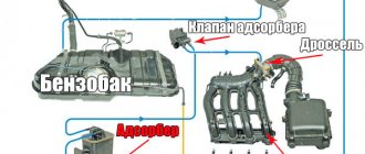
Carburetor internal combustion engine
Before we talk about breakdowns of carburetors and electrical equipment, we suggest you understand the scheme by which the system works:
- When the driver turns on the ignition, but does not start the engine, power is supplied through the high-voltage wiring harness to the motor terminals, and the indicators on the instrument panel light up.
- Next, the starter activates the crankshaft, as well as the entire piston group. In the same way, the voltage through the high-voltage wiring harness starts the generator. The panel continues to work.
- Then power from the device is supplied to the ignition coil, which begins to generate a pulse. The impulse arrives through the high-voltage wire harness to the distributor, the instrument panel works.
- After this, the crankshaft of the motor begins to rotate the distributor drive. The device begins to close the contacts, thus transmitting the discharge through the same high-voltage wire harness to the carburetor spark plugs. The instrument panel continues to operate normally.
Classic ignition
If you cannot start the engine on a carburetor, you need to pay attention to diagnosing the following elements:
- Inspect the electrical wiring between the coil and the generator. You need to check the contacts for breaks or oxidation, sometimes you can simply clean them, in some cases they require replacement. If the electrical circuit itself is in poor condition, then it may make sense to replace the wires.
- You should also diagnose the ignition coil. First of all, you need to check for the presence of a spark. To do this, remove the high-voltage wire from the distributor harness and bring it to the metal elements of the engine compartment. When you try to start the engine by turning the ignition key, a spark should appear from the high-voltage wire. If it is not there, then the coil is faulty and needs to be repaired or replaced.
- In addition, you need to check the distributor chain and the spark plugs themselves. If you see that the high-voltage wires in the harness are in a sad state, then it may make sense to change them. Carry out diagnostics of the internal slider, as well as the carburetor spark plugs themselves (video author - MR. Boroda).
Electronic ignition
The VAZ 2109 can be equipped with an electronic, that is, contactless switch, which is mounted between the coil itself and the distributor. The electronic system is designed to provide a better spark if the engine operates on a lean fuel mixture. If the pulse is too low or completely absent, as you were able to verify when checking for the presence of a spark, then it would be better to change the switch. If the installation of a new device does not solve the problem, it will be necessary to completely or partially change the electrical wiring. There is a possibility that the resistance level in the circuit is very high, and this contributes to a too weak spark.
Ignition coil
The VAZ 2109 car is equipped with an ignition coil whose operating principle is based on the principle of an open magnetic circuit.
Like many ignition coils, model 27.3705 consists of a core, primary and secondary windings. The coil body is filled with transformer oil.
A design feature of this ignition coil is the presence of a special one-time emergency safety valve. This valve is activated only when the oil pressure in the housing becomes higher than the standard one.
If the valve is triggered, immediately replace the ignition coil. If there were no such valve, the coil would simply rupture with the ensuing consequences.
Summary
We hope that we have covered in sufficient detail the danger that awaits owners of VAZ 2109 cars due to the poor technical condition of the standard wiring. This is especially true for older cars, which often have had more than one owner during their operation. And the best way to protect yourself and preserve your car is to correctly and timely replace the wiring.
Wiring VAZ 2109: special control is needed under the hood
Hello. In past records, I mentioned that I want to change the wiring harness and that I already have a wiring harness from the spot I purchased on the auto-parcel. But she needed further work. And if it had to be adapted to the carburetor. In the shoe where the bundle from the commutator and the reel should be connected, part of the wires did not suffice, and part was not in those nests. In addition, there was no starter relay. But there is no thin without good in this bundle were the findings for most sensors of the BSK and that was very pleased with the presence of the relay fogs (that luxury car was therefore a complete set of consumers) my PTFs were turned on directly can turn off forget and the xen sucks the power out of the battery is not childish.
I wired the wires of the color I needed from the old saloon spit and started to implement this business, but then I remembered about the speed sensor that it hooked in knows how and not from the place where the snot"s got a snot and it "s ordering to sort this thing out. It works, but when everything is hanging around like a spider web, it’s unpleasant and not practical. I also plan to put the janitors on the headlights together with the bilanzers and not later to climb into the wiring and not hang new snot decided to immediately include in the chain the planned consumers. He drew a schematics from the book for the washers of headlights in passing trying to understand how it works. Then he began to dig into his supplies of wires and realized that everything is short and if you do it from different colors with a bunch of twists then this is nonsense which will turn out sooner or later. Again going to Andryukha to parse I take from him for a half-waggon back plait from the chirp, then I went to the building store and bought there corrugated paper to hide there what I already prepared for the starter and speed sensor. And he began to ennoble. I also included the fan relay in the relay so that when the machine is turned off, it is also chopped off, and does not rotate until it cools down, making Akum unsuccessful. Here's what I got
The starter relay and output to the speed sensor
Fan relay and wires to the left headlight cleaning device
On the right-hand headlamp and pump
The scheme of additions
And now the wiring is ready. I changed for half a day tore the old set a new one, that day my drugan arrived set gravefeli. He reworked the carburetor on the injector. I quickly made my wiring and helped him ring and patch the braid from the brains, and there the nuts together twisted the fuel lines.
A completely different kind
It's nice to see
The result is satisfied with everything neatly hangs nothing, nothing closes and places like a bud, it would have become more just a little twisted, it was necessary to lead wires to the right headlight cleaner near the chips of fogs, and not in the region of the genes, but this is not critical. The motor must have its own leash with a chip.
Ignition coil malfunctions
The most common faults are:
- Interturn short circuit between the primary and secondary windings;
- Open circuit in the 1st or 2nd windings;
- Insulation breakdown of the second winding on the coil body.
The main signs of a faulty ignition coil:
- There are traces of oil leakage on the cover;
- Cracks and scabs on the lid;
- The ohmmeter readings are not correct (read on).
If these problems are detected, the ignition coil should be replaced.
Checking the resistance in the 1st and 2nd windings
Primary winding
To perform such work, you will need an ohmmeter and an ambient temperature of 20 - 25 degrees.
Connect an ohmmeter to the right and left terminals of the coil, the readings should be between 0.4 - 0.5 Ohms. For any other indicators, the coil is replaced with a new one.
Secondary winding
To check, connect the ohmmeter wires to terminal B and to the high-voltage terminal, which is located in the middle of the coil. The air temperature is the same 20 - 25 degrees. The ohmmeter readings should be in the range of 4.5 - 5.5 kOhm; if there are any other readings, the coil is replaced with a new one.
Insulation resistance per “body”
Everything is very simple, we connect one ohmmeter wire to the coil body, the second wire in series to each terminal. The ohmmeter reading in all cases should be at least 50 MOhm. For other indications, the coil is replaced with a new one.
Although the VAZ 2109 ignition system is not complex in its design, the principle of its operation is based on complex electrophysical phenomena, which means that you need to approach the adjustment and maintenance of the ignition carefully and competently.