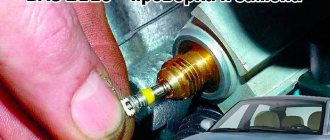
During operation of the injection power system, a portion of fuel is mixed into the passing air flow (or directly injected into the cylinders). But in order for the injectors to inject gasoline, it must be under pressure. Fuel is pumped by an electric fuel pump.
In this case, the pressure created inside the fuel system must be within a strictly specified range. And the fuel pressure regulator used in the design of the injection system maintains it at the required value.
Installation locations
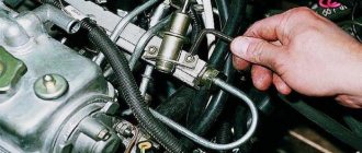
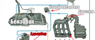
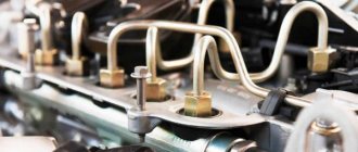
On cars, the injection system is equipped with a separate line for draining excess gasoline, which goes from the fuel rail to the gas tank (fuel recirculation). In such injectors, the regulator is installed directly on the fuel rail (or connected to it), so the unit quickly “reacts” to changes in engine operating conditions and adjusts the pressure in the rail. In this design of the power system, a mechanical type RTD is used.
There is another version of the injector - without gasoline recirculation. In this system there is no “return” at all, and regulation is carried out at the output of their fuel pump. A feature of such a system is the location of the regulator - in the tank or near it. An RTD is already used here, the operation of which is controlled by the ECU - the control unit, through a sensor installed in the ramp, monitors the necessary parameters and corrects them by sending signals to the regulator.
Power systems with electronic regulators are used less frequently than mechanical ones due to their complex design and, accordingly, lower reliability.
Location in the vehicle structure
A modern car in which such a device will be installed can use one of two regulator layouts:
- The fuel supply system line is equipped with a return line. In this case, the regulator, or valve, will be installed on the fuel rail. A supply hose will be attached to the valve inlet (input from the pump at one end, and output to the nozzles at the other), and a return hose is connected at the outlet;
- Main line without recirculation. In this case, the regulator is installed next to the fuel pump in the gas tank (often included in its design). Its operation is regulated either by the ECU or by the mechanism of the pump itself. Fuel is dumped in the tank itself.
The first scheme has several disadvantages. Firstly, if the unit depressurizes, gasoline or diesel fuel will spill into the engine compartment. Secondly, unused fuel is unnecessarily heated and returned to the gas tank.
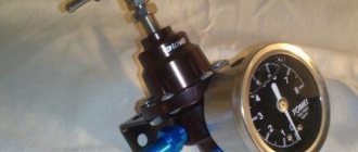
For each engine model, its own modification of the regulator is created. In some cars you can use universal RTDs. Such models can have manual adjustment and be equipped with a pressure gauge. They can be used as an alternative to the standard regulator, which is installed on the ramp.
Regulator design
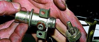
The design of the mechanical fuel pressure regulator is simple. It consists of a body, which is internally divided by a membrane into two chambers. One of them is called the fuel chamber, the second is called the vacuum chamber (or simply vacuum). Each of the chambers is connected to the system components by fittings and channels. The fuel chamber is connected through channels to the fuel rail, and a fitting for the line for draining excess gasoline (“return”) also comes from it. The vacuum chamber also has a fitting, which is designed to connect to the intake manifold.
A needle valve is fixed to the membrane, the seat for which is the channel of the drain line fitting. This valve is constantly in the closed position, and a spring installed in the vacuum chamber presses it to the seat.
Design and principle of operation
Fuel pressure regulator in closed (a) and open (b) positions.
The fuel regulator consists of the following elements:
- Frame. It is made of metal and has a high tightness necessary to prevent fuel leakage and loss of pressure.
- Membrane (diaphragm). Reacts to excess pressure and opens the drain line.
- Check valve. Located at the entrance.
- Spring. Places additional pressure on the valve diaphragm.
- Fittings for fastening fuel inlet and drain lines.
- Seals. Ensure the tightness of the system at the inlet and outlet.
The operating principle of a mechanical fuel volume regulator is simple. The membrane divides the internal space of the housing into two chambers (fuel and air). The first is supplied with fuel using a pump, which exerts some pressure on the membrane. The check valve prevents fuel from returning to the intake manifold, which allows the pressure necessary for engine operation to be created.
The classic valve design is a mechanical unit whose operation is based on pressure differences. In common rail systems, instead of a fuel regulator, a solenoid valve controlled by the engine ECU can be used.
On the reverse side of the membrane (in the second chamber) there is a spring that locks the regulator. This chamber is connected with a hose to the intake manifold, in which, under various modes, a certain level of air rarefaction is formed, which also affects the diaphragm. At the moment when the fuel pressure exceeds the total effect of the spring and vacuum in the intake manifold, the valve opens, dumping part of the fuel.
Thus, the lower the vacuum in the intake manifold, the greater the pressure of the fuel supplied to the fuel injectors. The control mode of the fuel regulator is engine idling, when the vacuum is minimal and the pressure is maximum.
Data from this mode are usually recorded on the outside of the housing, which simplifies the process of diagnosing and repairing the engine power system. When the engine stops, the valve closes completely, which maintains constant high pressure in the fuel rail (rail) and simplifies restarting.
Operating principle of the fuel pressure regulator
The principle of operation of the regulator is as follows: when the engine is stopped (when the pump is not pumping fuel), a spring through a membrane presses the valve to the seat on the drain channel, and it is in the closed position. After starting the engine, the fuel pump pumps gasoline into the ramp, from where it enters the fuel chamber of the RTD. While the pressure is insignificant, due to the stiffness of the spring, the valve remains closed, which will ensure an increase in pressure.
As the pressure increases, the fuel acts on the membrane, and as soon as it exceeds the spring stiffness, the membrane shifts towards the vacuum chamber, which pulls the valve along with it. As a result, the “return” channel opens slightly and part of the gasoline goes into the drain - the pressure is released to a level at which the spring again closes the drain channel with a valve. But as already noted, the fuel pressure regulator “adapts” to the operation of the engine. And for this, the vacuum created in the intake manifold is used.
The vacuum chamber of the RTD is connected to the manifold, so the resulting vacuum is transferred to the specified chamber. Let's consider the effect of vacuum on the functioning of the regulator using two examples:
- The engine is idling. In this mode, a large supply of gasoline in the ramp is not required, since the consumption at idle is minimal, which means that increased pressure is not needed. At XX, the throttle valve is closed and no air is supplied through it. As a result, a lack of air—a vacuum—forms in the collector. This vacuum, acting on the regulator membrane, creates additional resistance to the stiffness of the spring - its force is reduced and less fuel pressure is needed to open the valve; excess fuel is discharged at the lower limit of the operating pressure range.
- The motor is operating under maximum load. Fuel consumption in this mode is high and requires increased pressure in the rail, in fact, a reserve of it, so that it is enough for normal operation of the engine. Under this operating condition, the throttle valve is open and air flows freely into the intake manifold, which is why there is no vacuum. And since there is no vacuum, there is no additional resistance to the spring. Only fuel pressure is used to compress it. As a result, the reset occurs at the upper limit of the range, which ensures the necessary supply of gasoline in the ramp.
Device
The design of classic regulators consists of the following parts:
- Durable metal housing (must have perfect tightness, as it is subject to changes in fuel pressure);
- The interior of the body is divided into two cavities by a diaphragm;
- To ensure that the fuel pumped into the ramp is retained there, a check valve is installed in the housing;
- A rigid spring is installed under the diaphragm (in the part where there is no fuel). This element is selected by the manufacturer in accordance with the modification of the fuel system;
- There are three fittings on the body: two for connecting the supply (input to the regulator and output to the injectors), and the other for return;
- Sealing elements for sealing the high pressure fuel system.