Print this article Font size 16
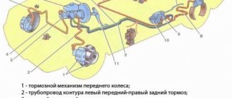
On a VAZ 2110 car, the brake system has a hydraulic dual-circuit drive. It’s no secret that you can’t go far in a car without brakes and safety in this case is close to zero.
Today we will talk to you about how the brake system works on the domestic VAZ 2110 car, or, more simply, the “ten”, we will analyze its main malfunctions, as well as ways to eliminate potential and existing problems.
Principle of operation
Hydraulic dual-circuit brakes with diagonal distribution are predominantly efficient and reliable. This is due to the fact that if one circuit fails, the second will allow your car to brake.
The circuit system is arranged as follows - one of them is responsible for the left rear and right front wheel, and the second circuit is responsible for the left front and right rear wheel.
This way, you will be able to brake without damaging the brakes or causing other problems with the system.
Consequences of brake fluid leakage from the GTZ
When brake fluid leaks from the master cylinder, brake fluid can get onto various parts of the car. As you know, TZ is quite chemically active and often damages other parts of the car.
For example, when liquid leaks, it can fall on the vacuum booster membrane, which will soon lead to its rupture and, as a result, air leakage from the receiver, and of course, replacement of the vacuum booster itself.
VUT membrane rupture
Also, when brake fluid leaks, it gets into part of the engine compartment, behind the steering rack, and causes great damage to the paintwork.
Braking system design
The most important component of the VAZ 2110 brake system circuit is a vacuum booster and a dual-circuit regulator. The latter is responsible for creating pressure in the rear brake devices.
The brake drive is equipped with a piping system, which is divided into two circuits, brake devices and hoses. They allow the front and rear wheels to brake.
To activate the braking system, a special pedal is located inside the passenger compartment at the driver’s feet. In the VAZ 2110 car it is located in the middle.
The main elements of the hydraulic drive are:
- Vacuum booster. Its design helps create pressure directed towards the master cylinder piston. This creates a braking effect.
- Pressure regulator drive. Through it, the brake fluid is directed to the rear devices of the braking system.
- Directly the brake pressure regulator of the VAZ 2110. Its function is to be responsible for the pressure force. The unit reduces or increases this indicator, depending on the load on the rear axle of the car.
- Master cylinder with reservoir and pistons. On the filler neck of this tank there is a sensor that monitors the emergency level of brake fluid.
- Front wheel brake mechanism. Its design includes cylinders, pads and a disc, plus a special alarm that warns of wear or malfunction of the lining.
- Rear wheel brake mechanism. Here the system is not disk, but drum. At least, this is the design the factory envisages. Some VAZ 2110 owners believe that drum mechanisms are not reliable and efficient enough, and therefore install disk devices in their place.
Let's get started
Only after a thorough inspection of the parts is the brakes properly pumped. The VAZ-2110 is placed on a flat platform. First, the rear right part is hung out and the wheel is removed. Next, check the fluid level in the plastic tank. It should be at an average level, but not below the minimum. So, add fluid to the MAX mark and start bleeding the brakes. First, clean the valve from dirt. Next, remove the protective rubber cap from it. A hose is placed over the valve head. Its second end is lowered into a clean transparent bottle (for example, a mineral water bottle).
Why do you need a pressure regulator?
Not every owner of a domestic “ten” will understand why the brake pressure regulator on a VAZ 2110 needs to be replaced. Simply, this name is not familiar to everyone. A popular designation for a regulator is a sorcerer.
This very sorcerer is located on the rear suspension of your car. It has a lever with a movable position. Depending on the moment of load on the spring, its position changes.
The voltage generated during actuation is directed and distributed to the brake piston. Pressing the piston pedal reduces the load on the rear pads. If the brake system is working properly, the loads are distributed evenly.
In order for the unit to function efficiently and without errors, it is necessary to adjust the brake pressure regulator on your VAZ 2110. This way you can prevent untimely wheel locking.
Which master brake cylinder is better for the VAZ-2110
The main brake cylinder of the VAZ-2110 can be repaired, but not always.
Currently, many companies produce analogues of the VAZ-2110 GTZ. Most of them are a higher quality product than recommended by the manufacturer.
Products from Fenox or Kraft are in great demand.
For aesthetes, we can recommend a product from Bosch, which costs three times more. In addition, many manufacturers produce parts with or without a tank.
Fenox
Brake cylinder FENOX T2043C3
For example, the company Fenox GTZ has the following article numbers:
- FENOX T2043C3 – this part is without a tank;
- FENOX T2043.5C3 – with tank.
Since the difference between these modifications is small, it is better to purchase a GTZ with a tank, especially if the old one contains dirt that is very difficult to remove.
Improvement of the braking system
Many VAZ 2110 owners agree that the factory brake system is far from perfect. Therefore, they decide to modernize and improve the unit using technical tuning.
A popular solution to the issue of brake efficiency is to replace drum mechanisms with disc ones. Of course, in the case of the “ten” we are talking about the rear wheels. When replacing brakes, be sure to take into account the fact that the rear wheels must brake more softly and somewhat later than the front wheels. This way the car won't skid and you won't fly off the road.
Another option is to remove the factory brake master cylinder and vacuum booster. Instead, units from Priora are excellent. Such tuning will eliminate vibrations and also allow you to use the brake pedal effectively and without excessive effort.
Regardless of the changes made to the brake system, after each modification it is mandatory to pump the brakes.
Brake system for VAZ 2110 - design, repair
If the brakes are faulty, driving a car is strictly prohibited, so it is important to monitor the condition of the brake system. The brake system needs to be monitored and repaired in a timely manner, and repairing the brake system on a VAZ 2110 is not lengthy and labor-intensive, but if you lack the skills and tools, it is better to contact specialists.
In order to know for sure whether the technical condition of the most important function of the car is in order, you need to understand how the brake system on the VAZ 2110 is designed. What sore spots do all the well-known “ten” have and how to solve possible or already pressing problems yourself.
Problems and their solutions
There are several common problems associated with brakes on a VAZ 2110 car. The reasons for their occurrence may be different, but the solution is always the same - timely and high-quality repairs.
- The brakes have completely lost their effectiveness, pressing the pedal does not cause any reaction. In such a situation, it is categorically impossible to drive anywhere under your own power, even if we are talking about a trip to a service station? How do you brake? About a wall or pillar? Call a tow truck and start repairs. In some situations, the problem can be solved on the spot, but these are temporary measures.
- During braking, strong vibrations are observed, most often in the steering column. At the same time, when you press the pedal, it is difficult to hold the steering wheel in your hands. There may be several reasons for this: If you have non-ventilated discs installed, similar situations may arise during rain or when braking through a puddle. Such devices do not like moisture, so to get rid of vibrations, replace the disks with ventilated ones;
- Another cause of vibrations is faulty drums. If there are dark spots on the working surface of the drums, the unit wears unevenly. Immediate repair or complete replacement of mechanisms is required;
- Be sure to check for signs of deformation on the front brake discs. They often cause vibrations.
- The vacuum booster air filter may be clogged, causing the brake pedal to feel stiff;
As you can see, the brake system of the VAZ 2110 car is far from perfect in its factory version, but it performs its functions effectively and reliably. All possible malfunctions can easily be fixed independently, but in some situations it is advisable to contact a professional service station.
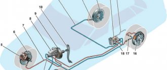
Hydraulic brake circuit diagram
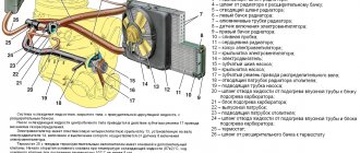
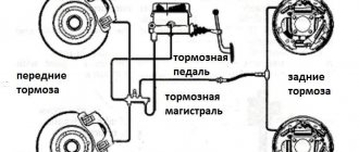
1 – front wheel brake mechanism; 2 – pipeline of the “left front–right rear brake” circuit; 3 – main cylinder for hydraulic brakes; 4 – pipeline of the “right front–left rear brake” circuit; 5 – master cylinder reservoir; 6 – vacuum booster; 7 – rear wheel brake mechanism; 8 – elastic lever of the pressure regulator drive; 9 – pressure regulator; 10 – pressure regulator drive lever; 11 – brake pedal; A – flexible hose of the front brake; B – flexible rear brake hose
The car uses a working brake system with diagonally separated circuits, which ensures high active safety of the car. One hydraulic drive circuit ensures the operation of the right front and left rear brake mechanisms, the other - the left front and right rear.
If one of the circuits of the service brake system fails, the second circuit is used to stop the vehicle with sufficient efficiency.
The hydraulic drive includes a vacuum booster 6 and a dual-circuit pressure regulator 9 for the rear brakes.
The parking brake system is driven by the brake mechanisms of the rear wheels.
2110 brake design
A dual-circuit hydraulic system with a vacuum brake booster is not uncommon on cars developed in the 80s. Easy to maintain, without unnecessary electronic bells and whistles, like ABS, cheap spare parts and pads. The front brakes are disc, and on models 2112, in the hatchback body, they are also ventilated with a larger diameter. This is because on the twelfth only 16-valve engines were installed and more effective brakes were needed to stop this incredible hundred-horsepower power. And also in order to cope with the Opel engine of 150 horsepower, which was also sometimes used for modification by dozens.
The rear brakes are tens of drum type, and the parking brake is mechanical. Everything is like in the good old classics. The car has a vacuum brake booster and the system is divided into two circuits. If one of them fails, the second one remains operational, so there won’t be a dozen left without brakes. The circuits work in a diagonal pattern - front-rear wheel diagonally. Also, the brake system of the VAZ 2110, the diagram of which is presented above, has a pressure regulator for uniform distribution of braking force, depending on the load of the rear axle. Both brake circuits are connected through the regulator.
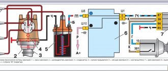
Vacuum booster
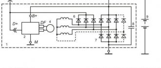
1 – vacuum booster housing;
2 – amplifier housing cup; 3 – rod; 4 – adjusting bolt; 5 – rod seal; 6 – sealing ring of the master cylinder flange; 7 – diaphragm return spring; 8 – amplifier pin; 9 – tip mounting flange; 10 – valve; 11 – hose tip; 12 – diaphragm; 13 – amplifier housing cover; 14 – sealing cover; 15 – piston; 16 – protective cover of the valve body; 17 – air filter; 18 – pusher; 19 – pusher return spring; 20 – valve spring; 21 – valve; 22 – valve body bushing; 23 – rod buffer; 24 – valve body; A – vacuum chamber; B – atmospheric chamber; C, D – channels The rubber diaphragm 12 together with the valve body 24 divides the cavity of the vacuum amplifier into two chambers: vacuum A and atmospheric B. Chamber A is connected to the engine inlet pipe through the check valve of the tip 11 and a hose.
The 24 valve body is plastic. At the exit from the cover, it is sealed with a corrugated protective cover 16. The valve body contains the main cylinder drive rod 3 with a support sleeve, rod buffer 23, valve body piston 15, valve assembly 21, pusher and valve return springs 19 and 20, air filter 17 , pusher 18.
When you press the pedal, the pusher 18, the piston 15, and after them the valve 21 move until it stops against the seat of the valve body. In this case, cameras A and B are separated. As the piston moves further, its seat moves away from the valve and through the resulting gap, chamber B is connected to the atmosphere. The air entering through filter 17, the gap between the piston and the valve and channel D creates pressure on the diaphragm 12. Due to the difference in pressure in chambers A and B, the valve body moves along with the rod 3, which acts on the piston of the main cylinder.
When the pedal is released, valve 21 moves away from the body seat and through the resulting gap and channel C of chambers A and B communicate with each other.
Pressure regulator drive
1 – pressure regulator; 2, 16 – pressure regulator mounting bolts; 3 – bracket for the pressure regulator drive lever; 4 – pin; 5 – pressure regulator drive lever; 6 – axis of the pressure regulator drive lever; 7 – lever spring; 8 – body bracket; 9 – pressure regulator mounting bracket; 10 – elastic lever of the pressure regulator drive; 11 – earring; 12 – earring bracket; 13 – washer; 14 – retaining ring; 15 – bracket pin; A, B, C – holes
Pressure regulator
1 – pressure regulator housing;
2 – piston; 3 – protective cap; 4, 8 – retaining rings; 5 – piston sleeve; 6 – piston spring; 7 – body bushing; 9, 22 – support washers; 10 – sealing rings of the pusher; 11 – support plate; 12 – pusher bushing spring; 13 – valve seat sealing ring; 14 – valve seat; 15 – sealing gasket; 16 – plug; 17 – valve spring; 18 – valve; 19 – pusher bushing; 20 – pusher; 21 – piston head seal; 23 – piston rod seal; 24 – plug; A, D – chambers connected to the main cylinder; B, C – chambers connected to the wheel cylinders of the rear brakes; K, M, N – clearances The pressure regulator regulates the pressure in the hydraulic drive of the brake mechanisms of the rear wheels depending on the load on the rear axle of the car. It is included in both circuits of the brake system and through it brake fluid flows to both rear brake mechanisms.
Pressure regulator 1 (Fig. Pressure regulator drive) is attached to bracket 9 with two bolts 2 and 16. At the same time, front bolt 2 simultaneously secures fork bracket 3 of lever 5 of the pressure regulator drive. A double-arm lever 5 is hinged on the pin of this bracket with a pin 4. Its upper arm is connected to an elastic lever 10, the other end of which is pivotally connected to the rear suspension arm bracket through an earring 11.
Bracket 3 together with lever 5 can be moved relative to the pressure regulator due to the oval holes for the fastening bolt. This regulates the force with which lever 5 acts on the regulator piston (see subsection 6.4.2). The regulator has four chambers: A and D (Fig. Pressure regulator) are connected to the main cylinder, B to the left, and C to the right wheel cylinders of the rear brakes.
In the initial position of the brake pedal, piston 2 (see Fig. Pressure regulator) is pressed by lever 5 (see Fig. Pressure regulator drive) through leaf spring 7 to pusher 20 (see Fig. Pressure regulator), which is pressed against the saddle under this force 14 of valve 18. In this case, valve 18 is pressed away from the seat and a gap H is formed, as well as a gap K between the piston head and seal 21. Through these gaps, chambers A and D communicate with chambers B and C.
When you press the brake pedal, fluid flows through gaps K and H and chambers B and C into the wheel cylinders of the brake mechanisms. As the fluid pressure increases, the force on the piston increases, tending to push it out of the housing. When the force from the liquid pressure exceeds the force from the elastic lever, the piston begins to move out of the body, and after it, under the action of springs 12 and 17, the pusher 20 moves together with the sleeve 19 and rings 10. In this case, the gap M increases, and the gaps H and K decrease . When the gap H is completely selected and the valve 18 isolates chamber D from chamber C, the pusher 20, together with the parts located on it, stops moving after the piston. Now the pressure in chamber C will vary depending on the pressure in chamber B. With a further increase in the force on the brake pedal, the pressure in chambers D, B and A increases, piston 2 continues to move out of the body, and sleeve 19 together with o-rings 10 and plate 11 under increasing pressure in chamber B, it shifts towards plug 16. At the same time, the gap M begins to decrease. Due to the decrease in the volume of chamber C, the pressure in it, and therefore in the brake drive, increases and will be practically equal to the pressure in chamber B. When the gap K becomes zero, the pressure in chamber B, and therefore in chamber C, will increase less degree than the pressure in chamber A due to throttling of the liquid between the piston head and seal 21. The relationship between the pressure in chambers B and A is determined by the ratio of the difference in the areas of the head and piston rod to the area of the head.
As the vehicle load increases, the elastic lever 10 (see Fig. Pressure regulator drive) is loaded more and the force from lever 5 on the piston increases, that is, the moment of contact between the piston head and seal 21 (see Fig. Pressure regulator) is achieved at greater pressure in the main brake cylinder. Thus, the effectiveness of the rear brakes increases with increasing load.
If the brake circuit “left front – right rear brake” fails, the o-rings 10, bushing 19, under the fluid pressure in chamber B, will move towards the plug 16 until the plate 11 rests on the seat 14. The pressure in the rear brake will be regulated by part of the regulator, which includes piston 2 with seal 21 and bushing 7. The operation of this part of the regulator, in the event of a failure of the said circuit, is similar to the operation with a working system. The nature of the change in pressure at the outlet of the regulator is the same as with a working system.
If the brake circuit “right front – left rear brake” fails, the pressure of the brake fluid forces the pusher 20 with the bushing 19 and sealing rings 10 toward the piston, pushing it out of the housing. The M gap increases and the H gap decreases. When valve 18 touches seat 14, the increase in pressure in chamber C stops, that is, the regulator in this case works as a pressure limiter. However, the achieved pressure is sufficient for reliable operation of the rear brake.
There is a hole in housing 1, closed by plug 24. Liquid leakage from under the plug when it is squeezed out indicates a leak in rings 10.
Master cylinder with reservoir
1 – main cylinder body;
2 – low pressure sealing ring; 3 – drive piston of the “left front–right rear brake” circuit; 4 – spacer ring; 5 – high pressure sealing ring; 6 – pressure spring of the sealing ring; 7 – spring plate; 8 – piston return spring; 9 – washer; 10 – locking screw; 11 – drive piston of the “right front–left rear brake” circuit; 12 – connecting sleeve; 13 – tank; 14 – brake fluid emergency level sensor; A – clearance Master cylinder with sequential arrangement of pistons. A tank 13 is mounted on the master cylinder body, in the filler neck of which a sensor 14 for emergency brake fluid level is installed. The high pressure O-rings 5 and the rear wheel cylinder rings are interchangeable.
Preparatory stage before pumping
Preparation for bleeding the system and removing air begins with choosing brake fluid. One of the most popular is a liquid produced in the USA by Step Up Brands + an analogue of DOT 4, its cost is approximately 400 rubles. The next popular brand in the mid-price category belongs to the Mobil brand. The most affordable option is to use a domestically produced product. Typically, such brands cost no more than 125 rubles per bottle, but this does not mean that their quality is low.
You can actually do the pumping yourself or contact the service. In the first case, you can save money, since the procedure is not the most complicated and even beginners can do it, and there are ways to level up both alone and with an assistant. When contacting the service, time is saved, and the cost of such a service starts from 500 rubles.
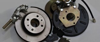
Front wheel brake
1 – brake disc;
2 – pad guide; 3 – caliper; 4 – brake pads; 5 – cylinder; 6 – piston; 7 – pad wear indicator; 8 – sealing ring; 9 – protective cover of the guide pin; 10 – guide pin; 11 – protective casing The front wheel brake mechanism is disc, with automatic adjustment of the gap between the pads and the disc, with a floating caliper and a brake pad wear indicator. The bracket is formed by a caliper 3 and a wheel cylinder 5, which are tightened with bolts. The movable bracket is bolted to pins 10, which are installed in the holes of the guide 2 of the pads. Lubricant is placed in these holes, rubber covers 9 are installed between the pins and the pad guide. Brake pads 4 are pressed against the grooves of the guide by springs, the inner one of which has a lining wear indicator 7.
A piston 6 with a sealing ring 8 is installed in the cavity of the cylinder 5. Due to the elasticity of this ring, the optimal gap between the pads and the disk is maintained.
Wheel cylinder
1 – block stop;
2 – protective cap; 3 – cylinder body; 4 – piston; 5 – seal; 6 – support plate; 7 – spring; 8 – crackers; 9 – thrust ring; 10 – thrust screw; 11 – fitting; A – slot on the thrust ring The brake mechanism of the rear wheel (Fig. Brake mechanism of the rear wheel) is drum, with automatic adjustment of the gap between the shoes and the drum. The automatic clearance adjustment device is located in the wheel cylinder. Its main element is a split thrust ring 9 (Fig. Wheel cylinder), installed on the piston 4 between the shoulder of the thrust screw 10 and two nuts 8 with a gap of 1.25–1.65 mm.
The thrust rings 9 are inserted into the cylinder with tension, providing a shear force of the ring along the cylinder mirror of at least 343 N (35 kgf), which exceeds the force on the piston from tension springs 3 and 7 (see Fig. Brake mechanism of the rear wheel) of the brake pads.
When, due to wear of the linings, the gap of 1.25–1.65 mm is completely removed, the shoulder on the thrust screw 10 (see Fig. Wheel cylinder) is pressed against the shoulder of the ring 9, as a result of which the thrust ring moves after the piston by the amount of wear. When the braking stops, the pistons are moved by the force of the tension springs until the cracks stop against the shoulder of the thrust ring. This automatically maintains the optimal clearance between the pads and the drum.
Tools that will be needed during the replacement process
To replace the brake cylinder you will need a tool.
Before starting any repair work, you should prepare thoroughly. Replacing the brake master cylinder is no exception. To replace this part you will need:
- Set of keys. Having a variety of sockets and socket wrenches will be a huge advantage.
- Screwdriver Set.
- Round nose pliers will help when changing cuffs.
- Special “brake” wrench for 10.
In addition, during the replacement process, brake fluid will spill out, which is generally advisable to replace with new one. DOT-4 brake fluid is suitable for the VAZ-2110.
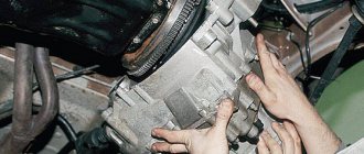
The process of removing the old part
In order to remove the brake master cylinder, you need to open the hood and do the following:
Parking brake system drive
The mechanically actuated parking brake system acts on the brake mechanisms of the rear wheels. The parking brake drive consists of lever 2, adjusting rod 4, equalizer 5, cable 8, lever 10 (see Fig. Rear wheel brake mechanism), manual pad drive and expansion bar 8.
1 – protective cap; 2 – sensor housing; 3 – sensor base; 4 – sealing ring; 5 – clamping ring; 6 – reflector; 7 – pusher; 8 – bushing; 9 – float; 10 – fixed contacts; 11 – moving contact
Mechanical brake fluid emergency level sensor. The sensor body 2 with a seal 4 and the base 3 with a reflector 6 are pressed by a clamping ring 5 to the end of the tank neck.
A pusher 7 passes through the hole in the base, connected to the float 9 by means of a sleeve 8. There is a moving contact 11 on the pusher, and fixed contacts 10 are located on the sensor body. The contact cavity is sealed with a protective cap 1. When the level of brake fluid in the reservoir drops to the maximum permissible, the moveable the contact moves down onto the fixed contacts and closes the circuit of the hazard warning lamp on the instrument panel.
What's next?
After this, close the valve. We repeat the operation again. This is done until the air is completely removed from the system. The liquid should not have bubbles. This is usually achieved in two to three repetitions. During bleeding, it is important to monitor the fluid level in the plastic reservoir under the hood. If the level has dropped to the minimum, add it to at least halfway and repeat the operation again. Upon completion of work, remove the rubber hoses from the valve and close the latter with a special cap.
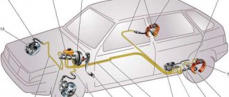
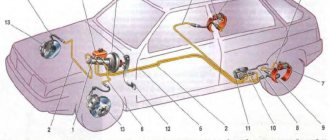
Device
Hydraulic brakes are installed on the machine and operate generally reliably. They are double-circuit and have a diagonal distribution. That is, if one part suddenly fails, then braking by another circuit is possible. For the sake of safety, the VAZ 2110 brakes operate diagonally, one circuit is the right front and left rear wheels, the other is also diagonal.
This device allows you to brake efficiently (without skidding and other troubles) even in the event of a malfunction, if the brakes in one of the circuits are lost.
Let's consider the design of the brake system. The hydraulic drive includes a vacuum booster, as well as a dual-circuit regulator that creates pressure in the rear brakes.
In addition, the hydraulic drive is equipped with pipelines divided into two circuits, hoses and brake mechanisms that provide braking to the front and rear mechanisms.
The hydraulic drive is activated by a pedal located in the cabin (middle). Here are the main components of the hydraulic drive:
- Vacuum booster.
It is designed in such a way that it creates pressure on the master cylinder piston, and thus causes braking; Vacuum brake booster - Pressure regulator drive.
It is through it that the working brake fluid flows to the rear brake mechanisms; Brake pressure regulator drive - The pressure regulator itself.
Already from the name it is clear that this device is responsible for the force of pressure, its decrease or increase. He does this depending on how loaded the rear axle of the car is; Pressure regulator - Main cylinder with pistons, equipped with a reservoir.
The filler neck of the tank is equipped with an emergency fuel level sensor; Master brake cylinder - Brake mechanism for the front wheel.
Its main parts are the disc, pads and wheel cylinders. The mechanism also provides an indicator to prevent complete wear and malfunction of the linings; Front wheel brake - Brake mechanism for the rear wheel.
Unlike the front disc brakes, the rear ones are drum brakes. This is the factory configuration. However, many car owners believe that their device does not provide high-quality braking, and change them to disc ones. Rear wheel brake
The brakes require attention. Without waiting for the warning light to come on, indicating a critical level of fuel fluid or wear of the linings, and even more so, without allowing the brakes to completely disappear, you need to carry out preventive checks.
Particular attention should be paid to all connections and hoses, since the “escaped” brake fluid will not make it possible to brake, and from here it’s not far from tragedy.
Bleeding brakes and replacing parts
Pumping is carried out for various reasons, but they have one thing in common: eliminating malfunctions associated with interference with the integrity of the entire system. VAZ 2110 brakes need to be bled after the following procedures:
- replacement of brake hoses and line pipes;
- installation and dismantling of front brake calipers;
- replacement of the “sorcerer” - pressure regulator;
- repair and dismantling of the main brake cylinder;
- replacing brake fluid.
If you need to remove or replace the vacuum brake booster on a VAZ 2110, bleeding is not a necessary procedure. However, only if the master cylinder piston has not accidentally fallen out. Brake fluid contains many special chemical additives designed to improve brake performance. During operation, under the influence of pressure, the temperature of the liquid increases, and over time the chemical composition changes, and the beneficial properties of the additives decrease.
On average, brake fluid retains its characteristics for about two years, so scheduled replacement is carried out at least once every two years.
Replacing brake pipes
During a preventative check of the system, it is necessary to inspect the condition of the tubes. They should be free from abrasions, cracks and other mechanical damage that lead to fluid leakage. For a more effective check, it is recommended to use a mirror and a lamp with a high degree of brightness. If damage is detected early, you can avoid problems with ineffective brakes (disc and drum) due to constant leakage of brake fluid. If faults are detected in the tubes, repair work is impractical; they should be urgently replaced.
To change the brake pipes with your own hands, you will need a special wrench to unscrew the fittings of the VAZ 2110 brake system on the main and other cylinders, as well as to disconnect the fasteners of the pipes themselves. Additionally, you will need a standard set of wrenches and a penetrating fluid such as WD-40. Since a leak will certainly occur due to dismantling, you also need to purchase new fluid for topping up. The replacement process is as follows:
- First of all, turn off the power to the on-board network by disconnecting the terminals from the battery.
- Replacement of pipes begins with the main brake cylinder, moving in turn to each cylinder on the front and rear wheels.
- Loosen the bolts on the wheels and lift the car on a jack (if it is not possible to use a lift or inspection pit).
- Following in turn, disconnect the tube fittings from the GTZ, close each hole with a plug.
- The tubes are carefully released from the fastenings, and the protective plastic casing must be removed.
- The tube fitting on the wheel brake cylinder is unscrewed and the tube is completely removed.
- The new tube is installed in the reverse order, strictly from the wheel cylinder to the cylinder under the hood.
If the plastic fasteners of the line were damaged during the dismantling process, they should be replaced.
The updated pipeline is purged with air, then the procedure should be completed by finally connecting the fittings to the holes in the cylinders.
All other tubes are changed in the same way.
Replacing calipers
In some cases, repair work requires dismantling the VAZ 2110 calipers on the front wheels. If you need to replace a VAZ 2110 brake disc or pads, the caliper is removed along with the hose assembly; there is no need to disassemble it. To work you will need the following set of tools:
- tire carrier and jack (unscrew and remove the wheel);
- 17mm socket and wrench.
Replacement algorithm:
- loosen the wheel bolts and jack up the car, unscrew the bolts and remove the wheel;
- remove the brake hose from the mounting on the shock absorber strut;
- Unscrew the two mounting bolts from the inside and remove the caliper, first unscrewing the brake hose.
The whole process takes no more than 10 minutes if you have all the necessary tools at hand. The new brake caliper is installed in the reverse order; it is recommended to replace the brake pads on the VAZ 2110 on both sides at the front along with it.
Replacing the pressure regulator
Sometimes when braking, the car pulls to the side or skids. One of the main reasons for this behavior is a faulty or misconfigured system pressure regulator. Problems with this element mainly occur due to fluid leakage, the presence of an air lock, or damage to rubber seals and hoses. If the problem is air in the system or a leak, the problem will be solved by removing the air lock and replacing the hoses, but if this is not the problem, you will need to remove and replace the regulator.
You can replace the “sorcerer” in a garage with your own hands without contacting service. Considering the primitive design of the VAZ 2110 brake system, even a beginner can handle the job, having wrenches, a screwdriver and pliers on hand. The procedure for replacing a sorcerer is simple if you follow the instructions:
- Lift the bracket up and thereby release the “sorcerer” drive lever. If necessary, you can open the earring using a screwdriver; all further actions are performed with a 10 mm wrench.
- After releasing the lever, you need to remove the bracket.
- You must first prepare a suitable container, which must be placed under the joints of the pipes and the holes of the regulator; brake fluid will begin to flow out from there.
- Unscrew all the brake pipe nuts and move them to the side, wait until all the fluid has drained.
- Plug the tubes with suitable devices (rubber caps for fittings from cylinders on wheels will do). Mark the tubes so as not to mix them up during installation.
- Unscrew the front and rear mounting bolts of the regulator bracket.
- Remove the regulator (there is no need to dismantle the drive).
- If it is necessary to replace drive elements, unscrew the bolt holding the lock lever, then disconnect the drive lever.
The new “sorcerer” is installed in the reverse order of removal; during assembly, it should be taken into account that the front bolt is longer than the rear. After completing the replacement procedure, all that remains is to compress the earring bracket with pliers and bleed the brakes.
Replacing the master cylinder
If the master cylinder is faulty, brake fluid may leak; when you press the pedal, you need to apply significant force, or vice versa, the pedal falls without any resistance. In most cases, this element cannot be repaired and must be replaced. The exception is damage to the rubber seals - in this case, you can use a repair kit, but proper operation of the part is not guaranteed. Therefore, the best option is to install a new cylinder.
Replacement Tools:
- screwdrivers (curly and flat);
- set of wrenches;
- container with liquid;
- syringe and fresh brake fluid.
Disconnect the wire connector from the brake fluid level sensor in the cylinder reservoir and unscrew the cap. Using a syringe, you should pump out all the liquid from the expansion tank. Next, use a 10 mm wrench to unscrew two tubes on the right and two on the left one by one. They should be carefully bent to the side so that they do not interfere with the subsequent dismantling of the old unit and installation of a new one.
To unscrew the bolts securing the cylinder to the vacuum booster, you need to partially remove the engine compartment trim by unscrewing several screws. After this, you can bend the upholstery and gain free access to the two fastening nuts.
They need to be unscrewed with a 17 mm wrench or a socket head. After this, the brake cylinder is removed along with the expansion tank. If you need to remove the tank, just pry it up with a screwdriver and pull it out of its seat. Installation of the new part is carried out in the reverse order, but some rules must be followed. You need to get the vacuum pump pusher into the hole on the cylinder, only after that the assembly is put on the studs and secured with two nuts. Next, you should connect and fix all the tubes one by one, but there is no need to tighten them, since you will still need to loosen them when pumping. Now you can screw the engine compartment trim back into place and fill the expansion tank with brake fluid.
Replacing fluid in the system
The main unpleasant property of brake fluid is its non-hygroscopicity - it absorbs moisture well. If the water content in its composition is more than 5 percent, under the influence of pressure it can boil, and the brakes will actually fail. The liquid should be free of various impurities and dirt; it should appear clean and transparent. In specialized service stations, to check the quality of the liquid, they use special testers that measure the percentage of moisture, but they are expensive - they cost about one and a half thousand rubles. But it is very convenient to have such a device in your use - you can always conduct a test and find out when you should replace the fluid in the brake system.
The replacement process cannot be called difficult and lengthy, but you need to know the features of the procedure, without which it is impossible to carry out a correct replacement. To work, you will need a suitable container to drain the waste liquid. You can also drain it onto the ground, but the old liquid can still be useful for flushing system parts. When using this substance, you should be careful, as it is a fairly aggressive chemical mixture and can corrode plastic parts or wire insulation. If it gets on the car body, wipe it off immediately with a dry cloth. Contact with skin and mucous membranes (eyes, mouth and nose) is not allowed. Draining brake fluid into sewer lines is also not allowed.
Before you begin the replacement, you need to unlock the “sorcerer”. To do this, just insert a flat-head screwdriver between the piston and the pressure plate. The fittings on the wheel cylinders should be cleaned of dust and dirt.
Now you need to open the hood and unscrew the cap of the expansion tank of the brake master cylinder. On all four wheel cylinders, unscrew the fittings and allow the fluid to drain; at the same time, the system will be cleaned of dirt and deposits. After some time, you can pour new fluid into the tank, but you do not need to tighten the fittings on the cylinders until the air bubbles disappear from the streams coming out of the fittings. After replacement, it is imperative to bleed the system to completely remove air.
Alarm Signals
The following symptoms are quite unsafe, please note:
- If the brakes are completely gone, then it’s clear that you can’t go any further, even to a service station! If independent repairs on site are beyond your capabilities, or simply impossible, you need to call a tow truck;
- When braking there is a strong vibration, especially felt in the steering column. You press the pedal, and it’s just hard to hold the steering wheel in your hands. There can be several reasons for vibration: • Many argue that vibration can occur due to the fact that there are non-ventilated disks. Their design is such that they really don’t like it when braking occurs in the rain, or even right in a puddle. No repair will help here - you need to replace the disks with ventilated ones; • Vibration may also occur if there is a problem with the rear drums. If upon inspection you find dark spots on the working surface, this indicates uneven wear. The vibration is usually very strong. Such drums need urgent repairs, and possibly replacement with disc brakes; • Check the front brake discs for deformation. At the same time, vibration is also observed.
- The brake pedal is too tight. There may also be several reasons for this: • A clogged air filter for the vacuum booster can cause the pedal to become stiff; • Check the vacuum booster itself. Its possible malfunctions are destruction of the diaphragm, tip, sticking of the check valve, damage to the hose connecting the intake manifold to the amplifier. In all these cases, a stiff pedal syndrome may occur, and repair of any of the indicated faults is necessary; • Also, the pedal may become stiffer as the pads wear, check them too.
- Hisses when you press the brake. If it hisses exactly when you press the pedal, you need to urgently check the vacuum booster, and then decide whether it needs repair or replacement. But if it hisses when you release the brake, then this is a normal phenomenon. Unless, of course, the hiss is too obvious.
Determination of breakdowns of the GTZ VAZ-2110
You can determine the faulty part yourself; to do this, you just need to know what to look for:
- Leaks in the brake fluid on the vacuum booster at the junction with the main brake cylinder indicate that the cuff in the cylinder is worn out.
In any case, you need to determine for yourself whether it’s worth bothering with disassembling the GTZ and repairing it or immediately installing a new part.
Is it worth buying a repair kit and is it profitable?
Buying a repair kit can save the money spent several times, but it will increase the time costs.
Based on the cost of the GTZ at 1,000 rubles, you need to think carefully about whether it is worth disassembling the brake cylinder for such a sum. Repair kits can be incomplete or complete . In any case, you need to purchase a complete one, since no one will measure the forces on the return springs.
You can also repair the brake master cylinder yourself.
An attempt to save money will result in a long procedure of disassembling, washing and drying all parts. When washing, you need to make sure that no gasoline or oil gets on the rubber parts, as this can damage them.
Therefore, the use of a repair kit can only be justified in the following cases:
- The assembled part is not available for sale.
- Inability to allocate 1,000 rubles for a purchase.
- The desire to understand the brake system with your own hands from beginning to end.
In other cases, it is better to immediately install the assembled part.