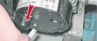
1200 rub. for the photo report
We pay for photo reports on car repairs. Earnings from 10,000 rubles/month.
Write:
Checking the generator voltage regulator may be necessary when problems with the battery begin to occur. In particular, it began to undercharge or overcharge. When such a malfunction occurs, it’s time to check the generator voltage regulator relay.
The relay should turn off at 14.2-14.5V
The task of this simple device is to regulate the voltage of the electric current that is supplied from the generator to the battery. When it fails, the battery is either not charged enough or, on the contrary, overcharged, which is also dangerous, since this significantly reduces the battery life.
Agree that such a prospect is not very good because of one small detail. This is why it is so important to monitor the operating condition of the voltage regulator (it can also be called a pill or a chocolate bar). But in order to properly check the voltage regulator, you need to know its type and several important features.
Types of Voltage Regulators
Having understood what types of these devices there are, what their features and properties are, a complete understanding of the procedures carried out during testing will come. This will also give the answer to what scheme, in what way and how to check the generator voltage regulator. There are two types of regulators:
In the first case, it is meant that the regulator housing is combined with the brush assembly directly in the generator housing. In the second case, the regulator is a separate unit, which is located on the car body, in the engine compartment, and wires from the generator go to it, and wires from it go to the battery.
A special feature of the regulators is that their housings are non-separable. They are usually filled with sealant or special resin. And there is no particular point in repairing them, since the device is inexpensive. Therefore, the main problem in this regard is to check the generator voltage regulator relay. Regardless of the type of regulator, the voltage symptoms will be the same.
Remote controller
ATTENTION! A completely simple way to reduce fuel consumption has been found! Don't believe me? An auto mechanic with 15 years of experience also didn’t believe it until he tried it. And now he saves 35,000 rubles a year on gasoline! Read more"
This often happens to drivers. The brushes of the generating device burn out. The regulator is built in along with the brushes. We have to change everything together. And here’s some advice from experts: it’s better to install an external regulator than a built-in one. The models released recently have not been praised very much.
Okay, do you think I’ll install an external one, but how do I connect it? It turns out that there is a convenient scheme that makes it easy to carry out all this modernization.
Some important points:
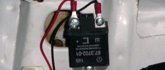
- do not confuse the chips on the regulator numbered 67 and 15 (the first should be connected to the generating device, and the second should go to the fuses);
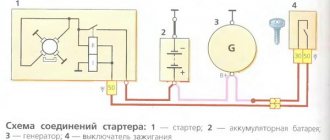
This is what the connection diagram looks like
In the lower photo we see a diagram that shows the connection of the already built-in regulator relay.
It is suitable for connecting to “fives”, “sevens”, VAZ 2104, if the PG is installed from a VAZ “kopek”. As you can see, the remote-type regulator relay is connected via two terminals. Pin 15 goes to the fuse.
The second pin 67 is connected to the generator. The wire is connected to the brush chip.
Also, the remote-type relay must be connected to ground - any part of the body.
A relay is nothing more than a switch that serves to close and disconnect individual zones of an electrical circuit that occur at specific electrical values. A machine relay is otherwise called a load voltage switch, and this is 100 percent true. When the power supply unit, fan or starter consumes more current than necessary, the relay trips.
The relay consists of an electric type magnet, an armature and a switch. In this case, the electromagnet is a cable twisted around an inductor with a magnetic rod, and the armature is a special plate that controls the contacts.
As soon as electrical voltage passes through the magnet winding, an electric field is created. A special pusher presses the armature against the core and, thereby, the contacts switch.
Attention. There are two types of relays used on VAZ cars. This is a non-contact relay-regulator and MER (electric). It is the diagram of the last relay that is shown in the picture below.
The non-contact relay or NERR is a fairly new unit that does not require any additional adjustments or regulation. As for the MED, this is an old-style device, the production of which has currently been suspended.
So, the BRN or built-in regulator is a device consisting of a microcircuit, a transistor and a housing with brushes. If the built-in regulator fails, it is replaced with a new one, or an external one is installed.
The external regulator is easy to install if you strictly follow the instructions.
Modernization involves dismantling and disassembling the generating device.
Symptoms of a problem
So, in case of low voltage, the battery simply will not charge. That is, in the morning you will not be able to start the car, the lights on the dashboard may not even light up, or troubles will arise while driving. For example, dim headlights at night, unstable operation of the electrical system (problems with electrical appliances - wipers, heaters, radio, etc.).
In case of increased voltage, there is a high probability of a decrease in the electrolyte level in the battery banks, or its boiling. A white coating may also appear on the battery case. When overcharging, the battery may behave inappropriately.
Signs, malfunctions and repair of the generator and voltage regulator
In addition, you can also identify the following signs of a faulty voltage regulator (in some cases, some of them may or may not be present, it all depends on the specific situation):
- the control light on the dashboard (although this may be a sign of other malfunctions, for example, that it has burned out, the contact has fallen out, and so on);
- after starting, the battery indicator on the dashboard does not go out, that is, there are obvious malfunctions in charging the battery;
- the brightness of the headlights becomes dependent on the engine speed (you can check this somewhere in a deserted place by placing the car against a wall and accelerating - if the glow changes, then most likely the voltage regulator is faulty);
- the car stopped starting normally the first time;
- The battery is constantly ;
- when the engine speed exceeds 2000 rpm, the indicators on the dashboard turn off ;
- the dynamic characteristics of the car decrease , this is especially noticeable at high engine speeds;
- In some cases, the battery may boil .
Reasons for failure of the relay regulator
The reasons for the failure of the voltage regulator may be:
- short circuit in the circuit, including interturn short circuit of the excitation winding;
- failure of the rectifier bridge (diode breakdown);
- reverse polarity or incorrect connection to the battery terminals;
- penetration of moisture into the housing of the regulator and/or generator (for example, when washing a car or driving in heavy rain);
- mechanical damage to the unit;
- natural wear and tear of the unit, including brushes;
- poor quality of the device being directly tested.
There are a number of simple methods for checking the regulator, regardless of whether the unit is removable or not.
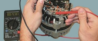
The simplest way to check the generator voltage regulator
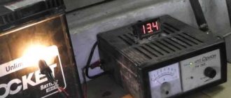
The simplest method of checking the regulator is to measure the voltage at the battery terminals with a multimeter. However, it is worth immediately making a reservation that the algorithm given below does not give a 100% probability of failure of the regulator. Perhaps the generator itself has failed. But the advantage of this method is that it is simple and there is no need to dismantle the device from the car. So, the algorithm for checking the generator voltage regulator with a multimeter is as follows:
- Set the tester to DC voltage measurement mode at a limit of about 20 V (depending on the specific model, the main thing is that it displays values up to 20 V as accurately as possible).
- Start the engine.
- Measure the voltage at the battery terminals in idle mode (1000. 1500 rpm). If the regulator and generator are working properly, the value should be within 13.2. 14 V.
- Increase the speed to 2000. 2500 rpm. In the normal state of the electrical circuit, the corresponding voltage will increase to 13.6. 14.2 V.
- When the speed increases to 3500 rpm and above, the voltage should not exceed 14.5 V.
If during the test the voltage values are very different from those given, then most likely the machine’s voltage regulator is faulty. Remember that the voltage should not fall below 12V and should not rise above 14.5V.
Voltage regulator 59.3702-01 – modification.
The proposed improvements to the regulator provide increased stability of the output voltage of a car generator when its load current and engine operating mode change. Modern cars have complex and multifunctional electrical equipment,
the reliable operation of which ensures the operability of the vehicle and the safety of its operation. The reliability of electrical equipment largely depends on the stability of the voltage in the on-board network. Ensuring that this voltage remains constant is a difficult task, especially during transient conditions when the generator rotation speed and its load current change sharply.
Together with a voltage regulator that maintains its constant, the generator forms an automatic control system. Under certain conditions, such a system may lose stability, which manifests itself in the form of sharp fluctuations in the output voltage of the generator and the charging current of the battery. Therefore, it is very important to ensure the stability of the control system under all operating conditions.
The most widely used today are electronic regulators operating in relay self-oscillating mode. Such a regulator, when the output voltage of the generator exceeds a given upper threshold, disconnects its excitation winding from the on-board network.
The current in the winding begins to decrease, which leads to a decrease in the generated voltage. As soon as it becomes less than the lower threshold, the excitation winding is reconnected to the on-board network and the current in it, and with it the output voltage of the generator, increases. Thus, the generator voltage fluctuates all the time, but its average value is maintained stable.
Regulators with “forced” PWM are more advanced. Due to the increased switching frequency of the excitation winding, the generator voltage in steady state is practically unchanged, although oscillations can still occur in transient modes.
Such regulators (one of them is described in the article by E. Tyshkevich “SHI voltage regulator.” - Radio, 1984, No. 6, pp. 27, 28) are not widely used, probably due to the fact that their parameters are not much better than conventional self-oscillating ones. Although they are mass-produced, they are difficult to find in stores. Sellers either know nothing at all about such regulators or claim that they are not in demand.
When operating a vehicle, an important parameter is the load capacity of the generator at low engine speeds. The minimum engine speed at which the battery is charged depends on it. Electronic voltage regulators most often lose stability precisely in situations where the rotation speed is low and the load current is high.
This feature is well known to motorists, some of whom replace electronic regulators with outdated contact-vibration ones, which are more reliable in this regard. But along with increased stability, they receive the disadvantages inherent in this type of regulator. Many motorists replace the standard battery with another one with increased capacity, as they believe that this improves the stability of the electronic regulators.
Unfortunately, fluctuations in the generator output voltage cannot be eliminated in car repair shops. At the same time, their employees claim that there is no malfunction, since the battery is still charging, although both the charging current and the generator voltage pulsate.
Considering all that has been said, the author tried to increase the stability of the standard electronic voltage regulator 59.3702-01. In Fig. 1 shows its circuit after the first modification, which boiled down to installing an additional circuit of resistor R8 and capacitor C2, highlighted in color in the figure. The imported S1M diode can be replaced with a domestic one from the KD202 or KD209 series.
The principle of operation of the regulator remains the same. As the voltage in the onboard network increases, applied to pin “15” of the regulator, the base potential of transistor VT1 relative to its emitter becomes more negative and at a certain value of this voltage (set by jumpers S1-S3), the transistor opens.
As a result, transistors VT2 and VT3 close, breaking the power supply circuit of the generator excitation winding connected between terminal “67” of the regulator and the common wire. But the current in a winding with significant inductance cannot stop instantly. It continues to flow through the opened diode VD2, gradually decreasing.
Along with the excitation current , the voltage supplied by the generator to the on-board network also decreases. After some time, transistor VT1 closes, and VT2 and VT3 open, which leads to an increase in current in the excitation winding of the generator and an increase in voltage. The described process is repeated periodically, and the average value of the generator voltage is maintained unchanged. Circuit R7C3 speeds up the process of switching transistors VT1-VT3.
When the voltage in the on-board network increases, caused, for example, by turning off a powerful load or increasing the engine speed, the newly installed capacitor C2 is charged, and the charging current, part of which flows through the base circuit of the transistor VT1, is proportional to the rate of voltage rise.
As a result, VT1 opens, and transistors VT2 and VT3 close earlier than it would have been without the capacitor. The decrease in current in the field winding also begins earlier, which significantly slows down or completely eliminates the increase in voltage caused by an external factor. A similar process occurs with a rapid decrease in voltage.
The resulting vibrations are damped and their range is significantly reduced. With slow voltage changes, the current through capacitor C2 is small and has virtually no effect on the operation of the regulator in steady state, as well as on the accuracy of stabilization of the average voltage value.
To check the stability of the voltage stabilization system, you can turn on and off a powerful consumer, such as headlights, while the engine and generator are running, monitoring the battery current with an ammeter.
In this case, the ammeter needle, after the initial maximum deviation from the steady-state position (this is associated with the inertia of the generator and is inevitable even with an ideal regulator), should return to the old or arrive at a new steady-state position monotonically without any oscillations.
It is possible, within certain limits, to regulate the dynamic characteristics of the system by selecting the capacitance of capacitor C2 and the resistance of resistor R8 connected in series with it. The minimum duration of the transient process is usually achieved with a capacitance of capacitor C2 slightly larger than that at which oscillations occur. A further increase in capacity leads to a significant slowdown in the system’s response to changing external conditions.
It should be noted that for a regulator with the described modification, the moment of its initial connection to the on-board network is very dangerous. Capacitor C2 is completely discharged at this time. Its charging current may well reach a dangerous value for transistor VT1 and damage it. Therefore, you should not significantly reduce the value of resistor R8 or eliminate it altogether.
Rice.
2 Although in the author’s practice failures of the modified regulator for the described reason did not occur, it is recommended to take measures to limit the current flowing through the base of transistor VT1, for example, include an additional resistor in the open circuit connecting the base with the connection point of resistors R6-R8, capacitor C1 and zener diode VD1. Its value should be chosen to be the maximum that does not noticeably worsen the operation of the regulator without capacitor C2.
It is known that to increase the service life of the battery, the voltage in the on-board network must increase with decreasing temperature. Therefore, in practice, seasonal voltage adjustment is carried out. In the regulator 59.3702-01, using jumpers S1-S3, closing resistors R1-R3, the average voltage of the generator can be changed within 13.8 ... 14.6 V. When the jumpers are removed, it decreases. Resistors R1—R3 can be replaced with one trimmer, which will allow you to regulate the generator voltage smoothly.
The purpose of the HL1 and HL2 LEDs has not changed after modification. They allow you to assess the performance of the control system. When the ignition is on and the engine is not running, only the HL2 LED should light, indicating that voltage is applied to the generator excitation winding. When the HL1 LED lights up when the engine is not running, it means that the regulator is faulty. When the engine is running, both LEDs light up.
Reducing its rotation speed or increasing the load on the on-board network leads to the fact that the brightness of LED HL2 increases, and HL1 decreases. As the rotation speed increases or the load decreases, the brightness changes in the opposite direction.
The regulator, before and after the described modification, was tested on an old car with an old battery. It was noticed that on this car, due to oxidation of the contacts, the resistance of the electrical wiring noticeably increased, and the internal resistance of the battery increased. Both of these factors lead to a decrease in the stability of the voltage regulation system.
With an unfinished regulator 59.3702-01, the ammeter needle, connected to the gap in the wire connecting the positive terminal of the battery to the car's electrical system, usually fluctuated with a range of 5... 10 A. Immediately after starting the engine, the range of fluctuations often exceeded 10 A and the headlights began to blink. When driving for a long time at high speed, the swing sometimes became less than 5 A, but this happened infrequently.
After the modification of the regulator discussed above, the ammeter needle never fluctuated with a range of more than 0.5 ... 1 A. After starting the engine, the headlights were on and never blinked. When driving for a long time at high speed, the range of the needle fluctuations usually decreased so much that they were difficult to notice.
During further refinement, resistor R7 and capacitor S3 were removed from the controller under consideration, and a node was inserted between the base of transistor VT2 and the connection point of the collector of transistor VT1 with capacitor C1 and resistor R9, the diagram of which is shown in Fig. 2. In the diagram shown in Fig. 1, places of circuit breaks are shown by crosses. Numbering of elements in Fig. 2 continues what was started in Fig. 1.
The regulator contains an exponential pulse generator based on logic elements DD1.1 and DD1.3 and a threshold device based on element DD1 2 with a pulse amplifier based on transistor VT4. The DD1 chip is powered by a voltage of 5 V from the integrated stabilizer DA1.
After modification, transistor VT1 serves as an amplifier for the mismatch signal. The voltage across its load—resistor R9—depends linearly on the difference between the current and nominal voltage values in the on-board network. This voltage is summed with the generator pulses using resistors R13 and R14. The amount is received at the input of the threshold device.
As a result, pulses are formed at its output, the duration of which depends on the deviation of the voltage in the on-board network from the nominal value, and the repetition frequency is constant (about 2 kHz). Through an amplifier on transistor VT4, they go to the base of transistor VT2 and control the voltage on the excitation winding of the generator.
A view of the modified regulator with the cover removed is shown in Fig. 3.
Additional parts are added to it by hanging installation. After installing this regulator on the car, the ammeter needle never fluctuated with a swing of more than 0.5 A. It can be assumed that with a low transient resistance of the electrical wiring contacts and with a new battery, the current fluctuations will be even less.
Author; A. SERGEEV, Sasovo, Ryazan region Radio 3\14
Checking the combined relay-regulator
Checking the VAZ 2110 voltage regulator
To perform the corresponding check, it is necessary to assemble the circuit shown in the figure. To do this, use a charger or power supply with an adjustable load (it is important that it be used to regulate the voltage value in the circuit), a 12 V light bulb (for example, from a turn signal or headlight, with a power of 3.4 W), a multimeter, and the regulator itself voltage (this can be from a Bosch, Valeo or other generator). It is advisable to have the wires used for switching with “crocodiles”.
Checking the voltage regulator of the generator 37.3701: 1 - battery; 2 — ground terminal of the voltage regulator; 3 - voltage regulator; 4 – terminal “Ш” of the regulator; 5 — output “B” of the regulator; 6 — control lamp; 7 — terminal “B” of the voltage regulator.
If you assemble a circuit in which the voltage is at a standard value of 12.7 V, then the light bulb will simply glow. But if you use a voltage regulator to raise its value to 14.14.5 V, then if the relay is working, the light should go out. Otherwise the regulator is faulty. That is, when the voltage reaches 14.14.5 V (depending on the model of the machine and, accordingly, the regulator) and above, the light goes out, and when it drops to the same level, it lights up again.
Checking the VAZ 2107 voltage regulator
Checking the voltage regulator on VAZ 2108/2109 cars
Until 1996, a VAZ 2107 with a 37.3701 generator was equipped with an old-style voltage regulator (17.3702). The verification procedure is given above. After 1996, a more modern generator of the G-222 brand was used (integrated regulator RN Ya112V (V1).
As you can see, the verification algorithm for all regulators is almost the same. The only difference is the cutoff values when the relay is activated.
Types of relay regulators VAZ
In recent years, a relay regulator with the designation 121.3702 was installed, which worked in symbiosis with the G-221 alternating current generator. But such a perfect device, which does not require any adjustments or additional maintenance, began to be used in the 90s. Initially, cars came off the assembly line with a PP-380 vibration regulator. So it needed adjustments, settings, and even maintenance. When working with the PP-380 regulator, you need to follow simple rules.
- Do not under any circumstances confuse the wires marked “67” and “15”. If this happens, the relay regulator will not function; its contacts located on top will be short-circuited. The result is a sharp increase in voltage at the output terminal of the generator, boiling of the battery, failure of all electricity consumers and the VAZ 2106 voltage regulator itself.
- It is not allowed to connect capacitors to the circuit of plug “67” to counteract radio interference. The contacts end up working incorrectly and as a result they are destroyed.
- It is prohibited to include any electrical energy consumers in the excitation winding circuit. Otherwise, the output voltage increases several times.
- The plugs numbered “67” and “15” cannot be connected to each other, since the output voltage increases significantly and the probability of failure of the semiconductor rectifier is very high.
- It is not recommended to remove the cover from the regulator, because dust and moisture can get into it, the contacts will begin to burn and become dirty, which will lead to improper operation of the mechanism. Installation of gaskets made from scrap materials is prohibited.
- Do not hit the regulator body, keep it clean.
- The electrical connections between the ground of the VAZ 2106 car and the device body must be reliable, with minimal resistance. If the connection is weak, then the probability of voltage increase is very high.
The requirements for the old type of VAZ 2106 relay-regulators are listed, but for the non-contact one, all points can be applied except 5. It will not be possible to remove the cover from the non-contact voltage regulator, since it does not have one. Therefore, if the entire unit fails, it will need to be completely replaced; repair is impossible.
Checking an Individual Regulator
Checking the voltage regulator of the G-222 generator: 1 - battery; 2 - voltage regulator; 3 - control lamp.
As a rule, separate voltage regulators were installed on old cars, including domestic VAZs. But some manufacturers continue to do this to this day. The verification process is similar. To do this, you need to have a power supply with a voltage regulator, a 12 V light bulb, a multimeter and a directly tested regulator.
To check, you need to assemble the circuit shown in the figure. The process itself is similar to the one above. In normal condition (at a voltage of 12 V), the light bulb lights up. When the voltage value increases to 14.5 V, it goes out, and when it decreases, it lights up again. If during the process the lamp lights up or goes out at other values, it means that the regulator has failed.
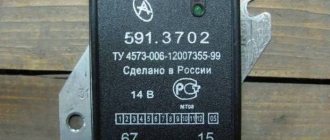
Checking relay type 591.3702-01
Relay test diagram type 591.3702-01
You can also still find a voltage regulator of type 591.3702-01, which was installed on rear-wheel drive VAZs (from VAZ 2101 to VAZ 2107), GAZ and Moskvich. The device is mounted separately and installed on the body. In general, the test is similar to that described above, but the differences are in the contacts used.
In particular, it has two main contacts - “67” and “15”. The first of them is a minus, and the second is a plus. Accordingly, to check it is necessary to assemble the circuit shown in the figure. The verification principle remains the same. In normal condition, at a voltage of 12 V, the light bulb lights up, and when the corresponding value increases to 14.5 V, it goes out. When the value returns to its original value, the light comes on again.
A classic regulator of this type is a device of the PP-380 brand, installed on VAZ 2101 and VAZ 2102 cars. We provide reference data regarding this regulator.
| Adjustable voltage at regulator and ambient temperature (50±3)° C, V: | |
| at the first stage | no more than 0.7 |
| on the second stage | 14,2 ± 0,3 |
| Resistance between plug “15” and ground, Ohm | 17,7 ± 2 |
| Resistance between plug “15” and plug “67” with open contacts, Ohm | 5,65 ± 0,3 |
| Air gap between armature and core, mm | 1,4 ± 0,07 |
| Distance between second stage contacts, mm | 0,45 ± 0,1 |
Testing a three-level relay
Regulated power supply
Some car owners install on their cars, instead of standard “chocolate bars,” three-level relays, which are technologically more advanced. Their difference is the presence of three voltage levels at which the battery power is cut off (for example, 13.7 V, 14.2 V and 14.7 V). The appropriate level can be set manually using a special regulator.
Such relays are more reliable and allow flexible adjustment of the cutoff voltage level. As for checking such a regulator, it is completely similar to the procedures described above. Just do not forget about the value that is set on the relay, and accordingly, check it with a multimeter.
Generator check
There is one method by which you can check the performance of a car generator equipped with a regulator relay 591.3702-01 with diagnostic elements. It is as follows:
- disconnect the wires that went to pins 67 and 15 of the voltage regulator;
- connect a light bulb to it (excluding the regulator from the circuit);
- Remove the wire from the positive terminal of the battery.
If, as a result of these actions, the engine does not stall, then we can say that the car’s generator is in order. Otherwise, it is faulty and needs to be checked and replaced.
Operating modes of a three-level relay-regulator
The “Minimum” level or mode, which corresponds to the generator output voltage of 13.6 V, is used for operation at air temperatures above 20°C and is used under high engine load (traffic jams, mountainous areas).
The “Normal” level assumes an output voltage of 14.2 V, corresponds to the average load on the engine, and is used in spring and autumn at ambient temperatures of 0–20 °C.
It is recommended to switch the regulator to “Maximum” mode at negative air temperatures. In the warm season, it is activated for a short time to charge the battery, which is heavily “dead” after a long stay, for example, by the speaker system or for other reasons.
The consumer qualities of some models of three-level relays are improved by introducing an additional semiconductor switch into the circuit, which ensures safe engine starting. This unit blocks the supply of current to the generator windings if it does not have a stable output voltage.
Something else useful for you:
Recommendations for increasing the service life of the regulator
In order to increase the service life of the voltage regulator, it is necessary to adhere to several simple rules aimed at implementing preventive measures. Among them:
- do not allow excessive contamination of the generator, periodically inspect its condition, and, if necessary, dismantle and clean the unit;
- check the tension of the alternator belt, tighten it if necessary (either yourself or in a car service);
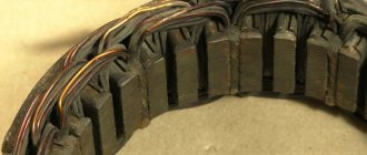
- monitor the condition of the generator windings, in particular, do not allow them to darken;
- check the contact on the control wire of the relay-regulator, both its quality and the presence of oxidation on it;
- Perform periodic voltage checks on the vehicle battery with the engine running.
Removing and installing the voltage regulator
Replacing the external voltage regulator VAZ 2101-2106
1) Using the “8” socket, unscrew the two nuts and remove the regulator.
2) Disconnect the two wires.
3) Attach the new regulator to the mudguard and connect the wires: orange to terminal “15”, and gray to terminal “67”.
Voltage regulator relay connection diagram
ATTENTION! Before starting the engine, make sure that the contact between the voltage regulator housing and the vehicle ground is reliable, and that the wires to terminals “15” and “67” are connected correctly.
Replacing the battery charging indicator relay
Work on replacing the VAZ 2106 charging lamp relay should be carried out in the following sequence:
- We unscrew the 2 fasteners of the charging lamp relay and remove the product from the installed studs.
- We mark the supply wiring with a marker or felt-tip pen to control the correctness of the reverse connection of the updated product. If the relay is incorrectly connected to the vehicle's power supply network, it stops functioning, which will create an emergency situation due to a sharp increase in the potential difference at the output contacts of the generator device.
- We disconnect the wire circuit, replace the relay with a working product and carry out the reverse installation.
When testing the charging lamp relay, it is strictly forbidden to make a short circuit between the output elements of the circuit, because this will cause defects in the current rectifier unit. Before testing the charge regulator relay, you must ensure that the alternator belt tension is optimal. Other energy resources should not be connected to the electrical circuit of the generator excitation winding, because the voltage drop on the VAZ 2106 charging relay under study may exceed the optimal values.
On the “classic” you can find 2 types of voltage regulator relays: built into the generator and external. The difference lies in the model of the generator that is installed on the car.
On older Zhiguli models (VAZ 2101, 2102, 2103, 2106, 2121 with carburetor engines) a G-221 generator is installed, and the external voltage regulator is a small “box”, which is secured with two nuts on the left mudguard of the body. It is precisely the replacement of such a regulator that will be discussed in this article.
On later VAZ models (2104, 2105 and 2107) there is a G-222 generator, and the voltage regulator is already built into the generator housing and is a small black “tablet”.
Cost and interchangeability
Built-in relay voltage regulator 71.3702 for generator G-222
The average price for a voltage regulator, both built into the brushes and remote, is about 100 rubles.
Models of generators G-221 and G-222 are interchangeable, that is, you can easily install a new generator from the “seven” for a “penny”, but you should pay attention to the correct charge of the battery. To do this, it is necessary to modify the electrical wiring according to the standard connection diagram.
Depending on the situation, either install an external voltage regulator relay, or, conversely, remove the external one and leave one built into the generator.
The normal voltage in the car's on-board network is considered to be in the range of 13.5-14.5 Volts.
The generator voltage regulator relay is an integral part of the electrical system of any car. It is used to maintain voltage within a certain range of values. In this article you will learn about what designs of regulators currently exist, including mechanisms that have not been used for a long time.
Electric relay device
An automobile charging relay, a photo of which can be found on our Internet portal, contains the following elements:
- Electromagnetic device - consists of a coil with a metal core that exhibits magnetic properties, and a wire of a certain cross-section that plays the role of a winding.
- An anchor element is a product made from a special plate that directs the contacts to the desired action, depending on the impulse received from an electromagnetic type coil.
- Position switch - combines the functions of switching, opening and closing contacts.
When voltage is applied through the electromagnetic winding of the coil, an electric field is created that attracts the armature element to the core, and the pusher, under the influence of the coil current, stirs the armature element, thereby switching the contacts of the “six” charging relay, the price of which is quite reasonable for Russian motorists. The correct connection of the charging relay can be seen in the image below
There are 2 main types of charging regulator relays used on “sixes”. These include:
- Automotive relay-regulator charging VAZ 2106 non-contact type, having the nomenclature number 121.3702. This is a relatively new electronic device used to complete the power equipment of the Six. The main advantage of this device is its complete autoregulation.
- The product under the symbol PP-380 with the same functions is installed on the “six” from the beginning of its release from the assembly line. The part is currently discontinued.
These charging relays are interchangeable, and, which is very convenient, without subsequent modifications and adjustments to the VAZ 2106 charging circuit, which is presented below
The VAZ 2106 charging circuit diagram includes a charging lamp relay (RS-702), which serves to receive signals from an indicator lamp on the instrument panel, which shows whether the charge current is flowing to the windings of the generator device and indicates its functionality. This charging lamp relay is located on the right fender liner in the engine compartment.
To check the functionality of the charging relay regulator of the VAZ 2106, you need to turn on the ignition, start the engine and achieve the required number of revolutions (2500-3000 rpm) of the power plant. Next, you should turn off all automotive electrical consumers (except for the ignition), and measure the potential difference at the output contacts of the product. The voltage at the ends should be 14.2 Volts.
If, when the charging relay is connected correctly, a problem is observed with its functionality, then this device should be repaired. To do this, you must have certain skills in electrical engineering and the ability to use an ampere-voltmeter and other measuring instruments and, possibly, a soldering iron. Otherwise, it is necessary to replace this element of the vehicle's electrical system, which can be purchased at a specialized store of automotive spare parts and components. Such a charging relay has a relatively low price, at least quite comparable with other components of the vehicle’s power supply system.
Basic automatic control processes
It doesn't matter what type of generator set is used in the car. In any case, it has a regulator in its design. The automatic voltage regulation system allows you to maintain a certain parameter value, regardless of the frequency at which the generator rotor rotates. The figure shows the generator voltage regulator relay, its diagram and appearance.
By analyzing the physics by which a generator set operates, it can be concluded that the output voltage increases as the rotor speed becomes higher. It can also be concluded that voltage regulation is carried out by reducing the current supplied to the rotor winding as the rotation speed increases.
What is a generator
Any car generator consists of several parts:
1. A rotor with an excitation winding, around which an electromagnetic field is created during operation.
2. A stator with three windings connected in a star configuration (alternating voltage is removed from them in the range from 12 to 30 Volts).
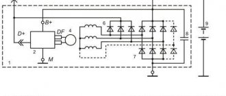
3. In addition, the design contains a three-phase rectifier consisting of six semiconductor diodes. It is worth noting that the VAZ 2107 generator voltage relay-regulator (injector or carburetor in the injection system) is the same.
But the generator will not be able to operate without a voltage regulation device. The reason for this is the voltage change over a very wide range. Therefore, it is necessary to use an automatic control system. It consists of a comparison device, control, executive, master and special sensor. The main element is the regulatory body. It can be either electrical or mechanical.
GU or generator
The generator in any automotive electrical circuit performs the dominant functions. The normal functioning and operation of the machine depends on it. Reliable PG is installed in all foreign cars and models of the domestic automobile industry.
For example, a GU is placed on the “six”, the charge of which satisfies the need for electricity of any standard component. If you do not overload the generating device of the “six”, then the car is capable of driving many, many more kilometers. However, it is important to carry out preventive procedures in a timely manner - monitor the belt tension and the condition of the brushes.
The GU is connected according to the classical scheme. Using the VAZ 2106 generator as an example, let’s consider its functioning. This GU is marked as G-221. It is an AC synchronous electric machine with ELMG excitation. A VB (rectifier) with 6 diodes is built inside the GU.
| 1 | generator rotor winding |
| 2 | generator |
| 3 | generator stator winding |
| 4 | generator rectifier |
| 5 | accumulator battery |
| 6 | ignition switch |
| 7 | battery charge indicator lamp |
| 8 | battery warning light relay |
| 9 | fuse box VAZ -2106 |
| 10 | throttle |
| 11 | temperature compensation resistor |
| 12 | additional resistors |
| 13 | voltage regulator |
A simple and understandable scheme that does not require any subtleties or specific knowledge. On the “six” the PG is located on the engine on the right. It is attached to the tension bar with a nut and to the bracket with its claws.
As you can see, the diagram shows an external regulator. It is marked with the number 13. The generator is indicated with the number 2, the fuse box is indicated with the number 9.
Generator operation
When the rotor begins to rotate, some voltage appears at the generator output. And it is supplied to the excitation winding through a control element. It is also worth noting that the generator set output is connected directly to the battery. Therefore, voltage is constantly present on the excitation winding. When the rotor speed increases, the voltage at the generator set output begins to change. A voltage regulator relay from a Valeo generator or any other manufacturer is connected to the generator output.
In this case, the sensor detects the change, sends a signal to a comparing device, which analyzes it, comparing it with a given parameter. Next, the signal goes to the control device, from which it is supplied to the actuator. The regulatory body is able to reduce the value of the current that flows to the rotor winding. As a result, the voltage at the generator set output is reduced. In a similar way, the mentioned parameter is increased in the event of a decrease in rotor speed.
SHI stabilizer
Pulse-width stabilizers are characterized by more stable operation, that is, an almost constant voltage is supplied to the vehicle network, and small deviations within the normal range are smooth. The device circuit uses the same parts as in the original, but at the same time the K561TL1 microcircuit is included. This made it possible to assemble a multivibrator and a short pulse shaper on the 1st node. The output switch control unit has also been simplified due to the use of a field-effect transistor with increased power.
Stabilizer operation cycle
When the ignition is turned on, a low logic level appears at the output of trigger DD1.1. As a result, transistor VT1 opens with the charging current of the capacitor SZ. It, in turn, begins to supply a high level to the inputs of element DD1.2, simultaneously discharging capacitor C4. When a low level appears at the output, DD1.2 opens the field-effect transistor VT3. The current from the stabilizer output flows through the excitation winding of the generator.
After the pulse stops, a high level is formed at the output of DD1.1 and transistor VT1 closes. Capacitor C4 is charged by the current passing through resistor R5 from the generator, which is controlled by transistor VT2. While the voltage on capacitor C4 drops to the lower switching limit of trigger DD1.2, it will switch. A high level will appear at its output, which will close transistor VT3. In order to protect the input circuits of the DD1 microcircuit, the voltage of capacitor C4 is limited by the diode VD4, which, when it is subsequently charged, will not lead to switching DD1.2. When a low-level pulse is again formed at the output of the generator, the process begins to repeat.
Thus, stabilization is carried out by the duration of the on state of the field-effect transistor, and the process is controlled by a measuring device, as well as a current generator. When the voltage at the generator output increases, the collector current of transistor VT2 increases. As the amperage increases, capacitor C4 begins to charge faster and the duration of the on state of transistor VT3 decreases. As a result, the current that flows through the excitation winding of the generator decreases and, of course, the output voltage of the generator decreases.
When the voltage at the output from the generator decreases, the current at the collector of transistor VT2 decreases. As a result, the charging time of capacitor C4 increases. This leads to a longer period of switching on of the transistor VT3 and the current that flows through the excitation winding of the generator increases. The generator output voltage also increases.
Two-level regulators
A two-level automatic control system consists of a generator, a rectifier element, and a battery. It is based on an electric magnet, its winding is connected to the sensor. The driving devices in these types of mechanisms are very simple. These are ordinary springs. A small lever is used as a comparison device. It is mobile and makes switching. The actuator is the contact group. The control element is a constant resistance. Such a generator voltage regulator relay, the diagram of which is given in the article, is very often used in technology, although it is morally outdated.
Operation of a two-level regulator
When the generator operates, a voltage appears at the output, which is supplied to the winding of the electromagnetic relay. In this case, a magnetic field arises, with its help the lever arm is attracted. The latter is acted upon by a spring, which is used as a comparing device. If the voltage becomes higher than expected, the contacts of the electromagnetic relay open. In this case, a constant resistance is included in the circuit. Less current is supplied to the field winding. The voltage regulator relay for the VAZ 21099 generator and other domestic and imported cars operates on a similar principle. If the voltage at the output decreases, then the contacts are closed, and the current strength changes upward.
Electronic regulator
Two-level mechanical voltage regulators have a big drawback - excessive wear of the elements. For this reason, instead of an electromagnetic relay, semiconductor elements operating in key mode began to be used. The operating principle is similar, only the mechanical elements are replaced by electronic ones. The sensing element is made on a voltage divider, which consists of constant resistors. A zener diode is used as a driving device.
The modern relay-voltage regulator of the VAZ 21099 generator is a more advanced device, reliable and durable. The executive part of the control device operates on transistors. As the voltage at the generator output changes, the electronic switch closes or opens the circuit, and additional resistance is connected if necessary. It is worth noting that two-level regulators are imperfect devices. Instead, it is better to use more modern developments.
Three-level regulation system
The quality of regulation of such structures is much higher than that of those previously discussed. Previously, mechanical designs were used, but today non-contact devices are more common. All elements used in this system are the same as those discussed above. But the operating principle is slightly different. First, voltage is applied through a divider to a special circuit in which information is processed. It is possible to install such a generator voltage regulator relay (Ford Sierra can also be equipped with similar equipment) on any car if you know the device and connection diagram.
Here the actual value is compared with the minimum and maximum. If the voltage deviates from the value that is set, then a certain signal appears. It is called a mismatch signal. It is used to regulate the current flowing to the excitation winding. The difference from a two-level system is that there are several additional resistances.
Modern voltage regulation systems
If the voltage regulator relay for the generator of a Chinese scooter is two-level, then more advanced devices are used on expensive cars. Multilevel control systems can contain 3, 4, 5 or more additional resistances. There are also tracking automatic control systems. In some designs, you can refuse to use additional resistances.
Instead, the frequency of operation of the electronic key increases. It is simply impossible to use circuits with electromagnetic relays in servo control systems. One of the latest developments is a multi-level control system that uses frequency modulation. In such designs, additional resistances are required, which are used to control logic elements.
List of elements.
| Symbol | Item name | Item type |
| VT1, VT2, VT4 | Transistors | KT3107B |
| VT3 | Transistor | KT817G |
| VT5, VT6 | Transistors | KT837X |
| VD1, VD4, VD5 | Diodes | KD209A |
| VD2 | Zener diode | D818B |
| VD3 | Zener diode | D814B |
| VD6 | Diode | KD202V |
| C1, C3 | Capacitors | K73-9-0.47uF |
| C2 | Capacitor | K73-9-0.22uF |
| R1 | Resistor | MLT-0.5-820 Ohm |
| R2 | Resistor | MLT-0.5-11 kOhm |
| R3 | Resistor | MLT-0.5-620 Ohm |
| R4 | Resistor | MLT-0.5-910 Ohm |
| R5 | Resistor | MLT-0.5-4.3 kOhm |
| R6 | Resistor | MLT-0.5-1 kOhm |
| R7 | Resistor | MLT-0.25-1 kOhm |
| R8 | Resistor | MLT-0.25-10 kOhm |
| R9 | Resistor | MLT-0.25-3.6 kOhm |
| R10 | Resistor | MLT-2-1 kOhm |
| R11 | Resistor | MLT-0.5-2.2 kOhm |
| R12 | Resistor | MLT-0.5-220 Ohm |
| K1 | Relay | Load current limiter |
| K2 | Relay | 115.3747 |
How to remove the relay regulator
Removing the generator voltage regulator relay ("Lanos" or domestic "nine" - it doesn't matter) is quite simple. It is worth noting that when replacing the voltage regulator, you only need one tool - a flat-head or Phillips screwdriver. There is no need to remove the generator or the belt and its drive. Most of the devices are located on the back cover of the generator, and are combined into a single unit with a brush mechanism. The most common breakdowns occur in several cases.
Firstly, when completely erasing the graphite brushes. Secondly, in case of breakdown of a semiconductor element. How to check the regulator will be discussed below. When removing, you will need to disconnect the battery. Disconnect the wire that connects the voltage regulator to the generator output. By unscrewing both mounting bolts, you can pull out the device body. But the voltage regulator relay of the VAZ 2101 generator has an outdated design - it is mounted in the engine compartment, separately from the brush assembly.
Car alternator output voltage problem
The list of functions of the generator necessarily includes recharging the on-board battery, which is carried out with a certain current to ensure a long service life. The simplest way to set its value is to slightly exceed the voltage taken from the output of the relay-regulator over the current value of the battery voltage. In this case, a serious problem immediately arises, which is due to the fact that, depending on the ambient temperature, the value of this excess should be different.
An obvious and fairly easily implemented solution to obtain a given output voltage using temperature correction of the regulator response threshold by installing an appropriate sensor is of low efficiency. The reason for this is that the temperature in the engine compartment, due to its proximity to a heated engine, differs from the air temperature, and it is not possible to determine the degree of this difference by simple means.
Another problem in determining the set value of the charging current is due to the fact that even at a constant ambient temperature, the load on the on-board network varies within wide limits. This leads to a “failure” in the battery charge level and difficulty starting a cooled engine after parking.
A good way to solve these problems is to switch to a relay-regulator, which makes the necessary adjustments by discretely changing the voltage that the generator creates. The specified value of the response threshold of this device is set by the driver independently using a three-position toggle switch. Some regulators connect automatically and contain an internal sensor that monitors the instantaneous value of the on-board network voltage. In both cases, the selection of the cutoff threshold is carried out taking into account external factors, primarily the current temperature and operating conditions of the vehicle.
Device check
The relay-regulator of the voltage of the VAZ 2106 generator, “kopecks”, and foreign cars is checked equally. As soon as you remove it, look at the brushes - they should be more than 5 millimeters long. If this parameter is different, the device must be replaced. To carry out diagnostics, you will need a constant voltage source. It would be desirable to be able to change the output characteristic. You can use a battery and a couple of AA batteries as a power source. You also need a lamp, it must run on 12 Volts. You can use a voltmeter instead. Connect the plus from the power supply to the voltage regulator connector.
Accordingly, connect the negative contact to the common plate of the device. Connect a light bulb or voltmeter to the brushes. In this state, voltage should be present between the brushes if 12-13 Volts are supplied to the input. But if you supply more than 15 Volts to the input, there should be no voltage between the brushes. This is a sign that the device is working properly. And it doesn’t matter at all whether the voltage regulator relay of the VAZ 2107 generator or another car is diagnosed. If the control lamp lights up at any voltage value or does not light up at all, it means that there is a malfunction of the unit.
Modern stabilizers
On modern vehicles, as a rule, self-oscillating relays are installed. They work on the principle of turning off the power to the excitation coil when the voltage reaches the upper limit of 13.5-13.8 V and connecting at the lower voltage threshold of 14.5-14.6 V.
Thus, the output voltage fluctuates constantly. Theoretically, this is not considered a disadvantage, since the voltage does not exceed acceptable limits. Still, this is not entirely safe. Surely experienced drivers know that the weak point of this type of relay is the transition moments when the rotor speed or load current changes sharply. A particularly unfavorable moment occurs with a large load current at low speeds. At these moments, voltage fluctuations often exceed the upper threshold. Due to the short duration of such surges, the battery will not fail immediately, but each time its capacity and, accordingly, resource is reduced.
This problem is solved in different ways. Sometimes car enthusiasts simply replace the self-oscillating relay with an outdated contact-vibration relay. A more optimal solution would be to replace the relay with a pulse-width stabilizer or upgrade the “native” one with the help of small additions.
conclusions
In the electrical system of a car, the voltage regulator relay of the Bosch generator (as, indeed, of any other company) plays a very important role. Monitor its condition as often as possible and check for damage and defects. Cases of failure of such a device are not uncommon. In this case, in the best case, the battery will be discharged. And in the worst case, the supply voltage in the on-board network may increase. This will lead to the failure of most electricity consumers. In addition, the generator itself may fail. And its repair will cost a tidy sum, and considering that the battery will fail very quickly, the costs will be astronomical. It is also worth noting that the Bosch generator voltage regulator relay is one of the leaders in sales. It has high reliability and durability, and its characteristics are as stable as possible.
Checking the work
- Switch position “min” - for operation at high ambient temperatures (above 20ºС), as well as during operation in particularly difficult conditions (traffic in traffic jams, long climbs in the mountains, etc.);
- The middle position of the switch is for operation at ambient temperatures from 0ºС to 20ºС;
- The “max” switch position is for operation at low ambient temperatures (below 0ºC), as well as for recharging a discharged battery.
Average load (PTF, dimensions, music and heater fan at first speed)
:
Maximum load, maximum number of consumers activated
:
Will you be installing a three-level voltage regulator on your car? Take part in the survey and leave your feedback in the comments.
Let us remind you that another reason for low voltage on the on-board network may be a bad ground.
Share on social networks: