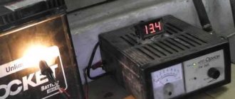
The VAZ 2107 generator is checked without removing it from the car. To do this, you will need a voltmeter or multimeter and a test lamp. Checking the VAZ 2107 generator consists of measuring the voltage it produces under load and without turning on consumers. If you suspect a generator malfunction, you must first check the tension of the generator drive belt. If the belt tension is normal, then check the voltage at the battery terminals. The voltage value at medium crankshaft speeds and high beam headlights on should be in the range of 14.5 - 13.5V.
Overcharging is characterized by increased voltage at the battery terminals, that is, a voltage above 14.5 V. The reason is related to the voltage regulator. Most often it is faulty, but poor contact in its connections is possible. The cost of the regulator is usually not high and in this case it is easier to replace it. Before replacing, clean the contact area between the negative terminal of the regulator and the generator housing.
Check procedure for different engine operating modes
An assistant will be needed to perform this operation. Sequence of actions to check the functionality of the generator:
- Set the digital or indicator multimeter to DC voltage measurement mode. We check the parameters at the battery terminals. According to the instruction manual, the voltage should be in the range from 11.9 to 12.6 V, perhaps a little less, taking into account the fact that the network consumes a small amount of energy.
- The assistant starts the engine and leaves it running at idle speed, we check the voltage again. If it drops, this means that the generator either does not work completely, or the parameters are insufficient to charge the battery.
- Exceeding the voltage value of 14.5 V for a long time will lead to boiling of the electrolyte in the banks.
If a generator malfunction is detected, you will need to check the diode bridge, electronic voltage regulator, stator and rotor windings, as well as the condition of the brush assembly.
In what situations is replacement necessary?
Wear of the element is characterized by such manifestations as cracks or tears in the canvas, worn teeth and uneven edges. If you ignore such a deplorable state of a very important element, it will come back to haunt you with overheating and boiling of the engine, independent operation of the battery, which will lead to its rapid discharge.
If the belt is severely worn, it also shows signs of noise to the owner - it begins to whistle, especially at low speeds. The next reason for a whistling belt may be water getting on its surface, which occurs due to worn-out pipes of the cooling system - antifreeze begins to leak.
Some belts - oak ones - whistle when the car starts in frosty weather, and after warming up the sound is lost. A weak tension is expressed by a whistle, but in this case it is quite easy to overtighten.
how to remove the generator
from a
VAZ
of the traditional model range.
More details: 2107
.html Subscribe!
Monitoring the performance of components
To perform this operation, it is necessary to remove the device from the vehicle and clean it of dirt. The verification procedure is as follows:
- We switch the multimeter to resistance measurement mode. We install the positive probe on terminal “30”, and the negative probe on ground. Readings close to zero indicate that the bridge or generator stator has failed.
- Positive diodes are checked by installing a positive probe on the terminal of one of the rectifier unit mounting bolts, and a negative probe on ground. Zero or close to zero instrument readings indicate that the diode bridge is faulty.
- To check the rotor, it is necessary to measure the resistance between the slip rings. In working condition it should be within a few ohms. If the resistance is near zero, then a short circuit has occurred in the winding.
The diode bridge and other faulty elements of the generator must be replaced with new ones from spare parts.
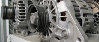
The generator is a miniature electrical station that supplies power to many components of the car: ignition, cooling, electrical wiring. Therefore, its failure will certainly entail other malfunctions. To prevent problems, you need to have this part diagnosed and repaired from time to time.
It will be useful for any motorist to know how to check the operation of a generator in a car, but first you need to understand the possible signs of a breakdown.
Types of relay-regulator
To exaggerate, there are only two types, but each works on the same principle, namely, “cuts” or increases the voltage to the desired level.
Combined with brush assembly. Usually it is mounted on the generator itself, in the housing where the brushes are located, there is also a relay regulator.
Separate. Usually it is mounted on the car body, the wires go from the generator to it, and only then to the battery.
The housings are non-separable and tight and of a different type (often filled with sealants or special adhesives), that is, they cannot be repaired. To be honest, they are quite cheap, especially for our VAZs, so it’s easier to buy a new one than to tinker with an old one.
These are the most common types, of course, previously there were so-called ones combined with terminals, but they didn’t catch on because the device is not very convenient, so I won’t talk about them.
If your relay is “broken” and is constantly recharging, then it’s worth changing it, but first you need to make sure that this is the problem. Now there are only two ways to check: - without removing it on the car itself, and checking an already removed relay. Let's look at both options.
Diagnostics without dismantling
To troubleshoot, you will need a multimeter and a test light. By measuring voltages, you can determine a potential breakdown that needs to be eliminated.
Initially, determine the voltage value while the engine is running at medium speeds with the load on (high beam, for example). Indicators in the range of 14.5-13.5 V indicate that everything is normal. Otherwise, repeat the test with electrical appliances turned off. Additionally, find out what voltage is supplied between pin 30 and the generator housing.
If, during the diagnostic process, the voltage at the battery terminals with the load on is below 13.5 V, and with the consumers turned off, the indicators slowly rise to 13-13.4. Then the problem most likely lies in poor contact from pin 30 to the battery and poor contact of the negative terminal to the motor housing.
To check the reliability of the connection in the 30th terminal of the unit, measure the voltage between the contact and the generator housing. If the indicator is significantly higher than the number on the battery terminals then do the following:
- Unscrew the nut securing the wire.
- Clean the connections.
- Pull the terminal nut that is located between the wire and the generator.
If you leave everything as is, a poor connection will cause the contact bolt to become very hot.
If the measurements show a value greater than 13.5 V, then do the following:
- Take a measurement between the positive side of the generator and its housing.
- If the value is the same as between the 30th pin and the housing, then eliminate the contact between the negative terminal of the generator and the motor housing.
- If the value is lower, check the voltage readings in the contact connections of the circuit from the generator to the battery.
- The same results at the battery terminals and pin 30 indicate that the generator itself is faulty. In this case, the rectifier bridge diode most often fails.
Generator faults
During the operation of any car, unpleasant situations often arise in the form of failure of one or another element. Niva is no exception, and most often the generator suffers.
If the generator seems to be faulty, it is recommended to check its functionality using a multimeter. To do this, you will need to start the engine and check the voltage at the battery terminals. The standard value that a multimeter should read is 13.6 V.
If the readings during measurement are higher, it means that a break or short circuit in the windings has occurred in the structure. The same can be said about the case when the voltage is below the specified number. This procedure is carried out regardless of the engine: injector or carburetor.
Also, if the breakdown is caused by another reason, you can replace the generator itself. Usually, for replacement, they turn to special service stations, but if necessary, the work can be done with your own hands.
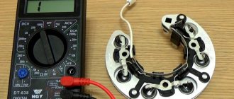
How to check a diode bridge with a multimeter?
Proceed in the following sequence:
Remove the diode bridge from the generator (otherwise the test will not work). Each diode must be tested separately.
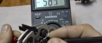
Set the multimeter to “beeper” mode. In this case, when the probes are closed, a characteristic squeak will be emitted. If there is no such function, you can set the tester switch to the “1 kOhm” position.
Touch the probes to the edges of one diode and take measurements by swapping the probes. The diode can be considered serviceable if it shows infinity in one direction and about 500-700 Ohms in the other.
If in both measurements the resistance is too low or, conversely, infinite, then the diode (group of diodes) is faulty.
Checking individual nodes.
If problems are detected in the operation of the electric generator, it is necessary to check individual components in order to decide on further actions - the ability to continue driving (if a breakdown occurred during a trip), the need for repair or complete replacement of the device.
In general, if problems arise on the road, it is recommended to turn off the generator and get to the nearest service station (on the battery, if there is enough charge) or in tow (tow truck). Operating a vehicle with a faulty power supply can result in serious problems (for example, complete failure of the on-board electronics).
Mechanical check.
At first glance, wear of bushings and bearings seems to be the least serious problem. However, their wear leads to increased friction, overheating of the device, and additional (albeit insignificant) engine power take-off. Distortions, destruction of parts, complete jamming of the rotor, and breakage of the drive belt are possible.
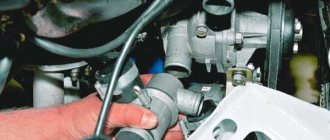
The integrity of the drive pulley is checked visually. To check the condition of the bearings (bushings), it is enough to rotate the rotor manually and try to move it perpendicular to the axis of rotation. When parts wear out, a characteristic sound is heard and the rotor rotates with significant resistance. Play perpendicular to the axis is a sign of significant wear and indicates the need to replace parts.
Brush unit.
To check the brushes, it is enough to dismantle the brush assembly and visually inspect the parts. If the brushes are severely worn, it is recommended to replace them. Before installation, you should check the condition of the collector.
Collector (slip rings).
The node is responsible for supplying the excitation voltage. Accordingly, significant wear of the collector rings leads to disruption of generation and instability of the output voltage. When brushes slide over the surface of worn rings, sparking is observed, which becomes a source of interference and malfunction of the on-board electronics.
The condition of the rings after dismantling the brush assembly is determined visually (by examining the surface) or by touch. A sign of significant wear is the sparking mentioned above.
The problem can be eliminated by grinding the surface of the collector rings (however, this cannot be done indefinitely - the thickness of the conductive layer is limited, and eventually the rotor will need to be replaced).
A short circuit between the rings is possible when current-carrying bridges are formed (from graphite or metal dust deposited when the brushes and rings operate). It can be eliminated by cleaning the surface of the collector assembly.
Condition of the windings.
In an electric generator it is possible:
- Breakage of stator phase windings, field windings.
- Interturn short circuit;
- Breakdown to the body.
Faults can be partially diagnosed using a tester. The device is used in resistance measurement mode, the measurement limit is units of ohms. Before measurements, disconnect the connected conductors and remove the brushes.
Checking the field winding:
- Measure the resistance between the collector rings. In the case of a serviceable winding, the value is 2.3-5.1 Ohms (nominal resistance 4.3 Ohms). “Infinity” on the ohmmeter indicates a break; a lower value is an indirect sign of an interturn short circuit.
- Check the winding for an interturn short circuit. 12 V is supplied to the slip rings from the battery through a multimeter turned on in DC measurement mode (limit more than 5 A). Readings of more than 5 A indicate the presence of a short circuit between the turns.
- Check for insulation breakdown by measuring the resistance between one of the collector rings and the housing. A value of more than 50 kOhm is a sign of breakdown.
It is impossible to carry out similar checks (except for testing for breakdown) without removing the device. First, you need to disconnect the winding leads from the rectifier bridge. Secondly, their resistance is low, about 0.3 Ohm, and it is difficult to measure it without precision instruments.
Rectifier bridge.
Failure of rectifier diodes is a fairly common malfunction that poses a serious danger. The breakdown of the diodes is equivalent to a short circuit at the output of the electric generator, creating shock current loads for the windings, overheating, insulation failure with further failure.
A detailed check and identification of a burnt-out diode can only be carried out by removing the bridge. However, it is possible to draw conclusions about its performance without dismantling the device.
- Disconnect the wires and dismantle the brush assembly.
- A tester (multimeter) measures the resistance between terminal B+ (30) and the housing. The measurement limit is 1 kOhm, “positive” probe at B+ (30). If the diodes are not broken, the measurement result is infinite resistance. Low resistance indicates a breakdown of the bridge strut (the most common fault).
- Change polarity (swap tester probes). The readings should correspond to a pair of open diodes (maximum within 200-500 Ohms).
- The additional rectifier that supplies the relay-regulator is checked in the same way - instead of terminal B+ (30), the probe of the device is placed on contact D+ (61).
Common breakdowns
Generator faults can be electrical or mechanical. These include:
- loss of functionality of the voltage regulator;
- breakdown of the rectifier unit (diode bridge);
- short circuit of stator windings;
- current short circuit in the rotor winding;
- wear of bearings and brushes.
Voltage regulator
The purpose of this unit is to normalize the voltage before feeding it into the automotive electrical circuit. You can check the serviceability of the regulator by checking the voltage that it supplies to the battery terminals. This indicator depends on the model and brand of the vehicle and varies between 13.5-15.5 V. Therefore, you should find out in advance what voltage your particular type of regulator produces. This can be done by studying the manual for using the machine. For example, you can take a VAZ 2107 or 2110 car, since these vehicles have the most typical faults associated with the integral and relays.
Using a Multimeter
To check the VAZ 2110 generator with a multimeter, you need to switch the device to voltmeter mode. Then you need to connect its probes to the battery terminals. The most important thing is to observe the polarity and turn off the car engine. The voltage normally varies from 12 to 12.8 V. Next, the procedure should be repeated, but with the engine running. The voltage readings should rise to 13.5-15.5 V. Lower and higher voltage values indicate a malfunction of the generator.
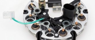
The main function of the diode bridge on the VAZ 2107
The diode bridge of the VAZ 2107 generator is its integral and integral part, which serves to transform alternating current into direct current. The current is converted due to the fact that the vehicle's on-board network has a constant voltage of 12 V. An alternating current is supplied to the bridge, which is converted, and then goes to the battery in rectified form. And the voltage is removed from the battery and used to power all electrical appliances on the car.
This is interesting! Many people are accustomed to thinking that the on-board network of a car has a voltage of 12V. However, 12V is the battery voltage at rest, and in order to charge it, a charge of 13.5 to 14.5 volts must be generated. To ensure normal voltage supplied from the battery, the diode bridge is assembled from 2D219B diodes.
Signs and reasons why a diode bridge breaks
Malfunctions of the rectifier unit on the seven and other cars lead to complete immobilization of the car. If at least one diode located inside the generator fails, the supply of charging current to the battery will stop. The car will not drive for a long time without charging the battery (maximum 1.5-2 hours, provided that the car has a new and working battery and all electricity consumers are turned off) . Like all parts on a car, diodes tend to deteriorate (burn out), so if a decrease in the voltage of the on-board network is detected, which usually drops below 12V, and then begins to gradually fall, then the device should be checked and repaired.
The causes of breakdowns of the generator rectifier unit are as follows:
- Moisture getting into the generator. This can be either condensation or water that comes from outside during the operation of the car in rainy weather.
- Development of diode life. Usually in this case one diode fails, while all the others remain intact. The average service life of diodes is about 10 years, but it also depends on the mileage of the car.
- Burnout due to motorist negligence. Most often, diodes burn out when the car is not properly lit. If you light it incorrectly, then in this case you may have to change not only the diode bridge, but also the entire generator.
The first symptoms of rectifier unit breakdowns are identified by the following signs:
- The voltage of the on-board network decreases while the engine is running. This can be detected by the presence of an electronic voltmeter, which can be installed independently by the owner of the VAZ 2107. If the car has an on-board computer, it will also notify the driver of the malfunction. If there is no voltmeter or on-board computer, then a decrease in voltage can be diagnosed by such a sign as a decrease in the brightness of the lighting fixtures.
- The car loses power, and the longer you continue to drive with a faulty generator, the more the battery will discharge.
To establish the exact cause of such symptoms on the VAZ 2107, it is necessary to test first the charging current of the generator, and then the diodes. Sometimes the cause of a decrease in voltage may be oxidation of the terminals and contacts on the generator, and after cleaning them, the problem will be solved.
Checking the diode bridge
You can find out why the on-board network voltage is decreasing by checking the generator to ensure its serviceability. Burnout of the generator winding occurs rarely, but such a breakdown cannot be ruled out. The diode bridge can be checked by the vehicle owner independently without the need to visit a service station. If the check shows that the element is working, it means that the generator itself needs repair, but looking ahead, it must be said that sometimes it is easier to buy a new element than to change the winding on the old one.
Types and location of voltage regulators
As you know, the VAZ 2107 car began to be produced a very long time ago. And over the years, not only different motors were installed on it, but also different voltage regulators. On the earliest models, the relay regulators were external. On later “sevens” the regulators were internal three-level. Let's take a closer look at these devices.
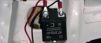
External voltage regulator VAZ 2107
It is the external voltage regulator that many motorists in the old fashioned way call a “relay-regulator”. Today, external voltage regulators can only be seen on very old “Sevens” produced before 1995. These cars were equipped with an old generator model 37.3701, which was equipped with external relays.
External relay regulators were installed on the very first VAZ 2107 models
The external regulator was located under the hood of the car; it was mounted on the left front wheel arch of the car. As a rule, external relays were made on the basis of a single semiconductor, although after 1998 on some VAZ 2107 there were external regulators made on a common printed circuit board.
The external regulator was not built into the generator, but was located under the hood of the car
External relays had certain advantages:
- Replacing the external regulator was fairly easy. It was held on by only two bolts, which were not difficult to reach. The only mistake that a beginner could make when replacing this device is to mix up terminals 15 and 67 (they are located next to each other on the regulator);
- the cost of the external regulator was quite affordable, and they were sold in almost all car stores.
Of course, the device also had disadvantages:
- bulky design. Compared to later electronic regulators, the external relay seems very large and takes up too much engine compartment space;
- low reliability. External VAZ regulators have never been of high quality. It is difficult to say what is causing this: the low quality of individual components or the poor build quality of the device itself. But the fact remains a fact.
Internal three-level voltage regulator
Internal three-level voltage regulators began to be installed on the VAZ 2107 starting in 1999.
The internal regulator began to be installed on the VAZ 2107 after 1999
These compact electronic devices were built directly into car generators.
The internal regulator is mounted directly into the VAZ 2107 generator
This technical solution had its advantages:
- compact sizes. Semiconductors were replaced by electronics, so now the voltage regulator fits in the palm of your hand;
- reliability. It’s simple: there’s nothing special about electronic devices that breaks. The only reason why a three-level regulator could burn out is a short circuit in the on-board network.
There are also disadvantages:
- difficulty of replacement. If there were no particular problems with external regulators, then to replace the internal relay the car owner first needs to get to the generator. To do this, he will have to remove the air filter and a couple of air ducts, which requires patience and time;
- difficulty of acquisition. As you know, the VAZ 2107 has long been out of production. So getting new components for the “seven” is becoming more and more difficult every year. Of course, this rule does not apply to all details. But internal three-level voltage regulators for the VAZ 2107 are among the parts that are not so easy to find today.
This is interesting: Checking diesel engine injectors, malfunctions and cleaning