We will talk about the voltage regulator.
In every car, even in the VAZ 2106, the most complex design is the power supply system. The operation of all electrical receivers in the car depends on how well it functions. The power supply system consists of two power sources - an alternator and a battery. A rectifier unit is installed inside the generator; it consists of conductor diodes that convert three-phase alternating voltage to direct voltage. To stabilize the voltage at the output of the device, a relay regulator is used. It will be discussed in this article.
Purpose of the voltage regulator
The purpose of using this device is to stabilize the voltage as much as possible in the entire electrical network of the car. If you power the generator excitation winding without a regulator, the output voltage will fluctuate over a very wide range. More specifically, its value will vary in the range from 10 to 30 Volts.
And if all electrical receivers are designed to operate under a voltage of 12 Volts, then we can conclude that they will become unusable instantly. The likelihood that the electrical wiring will begin to melt increases. Also, semiconductor diodes can easily not withstand the increased load. To prevent this, voltage regulator relays are used. What designs there are will be discussed below.
Technical characteristics of the VAZ-2110 launch vehicle
The voltage regulator relay for the VAZ-2110 generator has the following characteristics.
Regulation voltage with battery at a temperature of 25 o C and a load of up to 3A, V
Regulation voltage with battery at a temperature of 25 o C and a load of more than 3 A, V
Operating temperature range, o C
Maximum output circuit current: standard/agreed with the manufacturer, A
Permissible long-term exposure to high voltage, V
Permissible exposure to high voltage for up to 5 minutes, V
Design of contact relays of regulators
Even 20-25 years ago, contact-type relay regulators were installed on VAZ 2106 cars. Today they are outdated. Car generators use exclusively electronic devices. But to understand the principle of operation, you need to consider contact systems. The basis of such a mechanism is the winding, which magnetizes the metal core. The winding contains about 1300 turns of copper wire.
If you are diagnosing this winding, you need to know that its resistance is 17 ohms. If during diagnostics it turns out that this value is much different from the reference value, then there is either an interturn short circuit or a short circuit to the device body. The design also includes contacts made of tungsten. A specially designed magnetic shunt, a plate designed to make adjustments.
Bracket, suspension, small springs, adjusting screws on a plate with terminals. But the most important thing in the design is resistance (fixed resistors). The regulator switches these resistors. Depending on the voltage at the generator output, their connection diagram changes. The maximum resistance value in the circuit is 80 ohms.
How does a mechanical voltage regulator work?
Now let's look at the principle of operation of a mechanical type regulator. When you start the engine, the generator rotor begins to rotate. If the rotation speed does not exceed two thousand revolutions per minute, then the voltage at the generator output is stable. It does not exceed 14.8 Volts. When the engine and generator operate in this way, the regulator does not function and passes current to the excitation winding. But as soon as you increase the crankshaft speed, the relay-regulator comes into operation.
In this case, the winding connected to the brushes instantly responds to excess voltage at the output terminal of the generator set. The winding is magnetized by the core and attracts the armature. This opens the contacts. And if, when operating at low speeds, only one resistor was connected to the circuit, then when the speed is exceeded, all three are used. This reduces the voltage supplied to the excitation winding of the VAZ 2106 generator.
How to check the regulator
Every motorist should know how to check the VAZ-2106 charging relay. Main conditions:
- A voltage of less than 14 Volts must pass through the device. For diagnostics, power from the car battery is connected to it.
- If the voltage is above 14 Volts, then it should not pass through the regulator. To check the circuit, the elements are connected, and the car battery and, for example, two AA batteries connected to it in series are used as power.
The main sign that the VAZ-2106 charging relay has failed is the voltage at the battery terminals is below 13.6 Volts.
Design of an electronic voltage regulator
Mechanical ones are a thing of the past; at the moment, in car generators you can only find non-contact designs of voltage relay regulators. Their advantage is obvious. Their service life is much greater than that of mechanical ones, since there are no moving contacts that are constantly in motion. From this we can conclude that electronic type relay regulators are more reliable. Such systems are used on all modern cars.
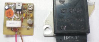
If you disassemble the voltage regulator, you can see either a small board on which there are thyristors and zener diodes that regulate the voltage, or a solid semiconductor crystal on which the entire structure is made. The functions of the electronic device are exactly the same as those described above for the mechanical regulator. On VAZ 2108 and newer cars, the voltage regulator is structurally combined with a brush mechanism.
GU or generator
The generator in any automotive electrical circuit performs the dominant functions. The normal functioning and operation of the machine depends on it. Reliable PG is installed in all foreign cars and models of the domestic automobile industry.
For example, a GU is placed on the “six”, the charge of which satisfies the need for electricity of any standard component. If you do not overload the generating device of the “six”, then the car is capable of driving many, many more kilometers. However, it is important to carry out preventive procedures in a timely manner - monitor the belt tension and the condition of the brushes.
Diagnostics of the voltage regulator
You can check it in several ways. Start the engine and let it run until its temperature reaches operating temperature. Turn on the low beam headlights and fog lights (if any). Arm yourself with a multimeter and measure the voltage on the battery. The maximum value should be 14.8 Volts. If you observe an excess of this value, then you need to change the voltage regulator relay. This is the easiest way to diagnose a device.
The one in which you need to remove the regulator from the generator will be a little more complicated. True, for this you need to do very little. Using a Phillips screwdriver, unscrew the two bolts, disconnect the wire and remove the device along with the brush assembly. This way the voltage regulator is removed on VAZ 2108 and similar models. If it is installed in the engine compartment, as in the VAZ 2106, then removing it is much more convenient.
For diagnostics, you will need a regular light bulb designed to operate at 12 Volts. It is desirable that its power be no more than three watts. The regulator has two terminals, designated by the Russian letters “B” and “V”. With their help, the device is powered from a DC source. A light comes on between the contacts that go to the brush mechanism.
If the output of the power source is no more than 14 Volts, then the light should be on. If it rises above 15 Volts, the lamp should go out. If in both cases the light bulb lights up or does not light up at all, then there is destruction of the semiconductor elements. Then only a complete replacement of the regulator will help.
Each car is equipped with a voltage stabilization device. On the “sixes” a VAZ 2106 generator voltage regulator relay is installed. The task of the device is to maintain the voltage level of the on-board network.
Checking and replacing the voltage regulator relay VAZ 2107
You can also check the relay regulator in a garage, but this will require several tools. Here they are:
- household multimeter (the accuracy level of the device must be at least 1, and the scale must be up to 35 volts);
- open-end wrench 10;
- flat screwdriver.
A simple option for checking the regulator
First of all, the relay regulator must be removed from the car. This is not difficult to do; it is secured with just two bolts. In addition, during the test you will have to actively use the battery, so it must be fully charged.
- The car engine starts, the headlights turn on, after which the engine idles for 15 minutes (the crankshaft rotation speed should not exceed 2 thousand revolutions per minute);
- The hood of the car is opened, and the voltage between the battery terminals is measured using a multimeter. It should not exceed 14 volts, and should not be lower than 12 volts.
A difficult option for checking the regulator
This option is used in cases where the failure of the regulator cannot be determined in a simple way when checking (for example, in situations where the voltage between the battery terminals is not 12 volts or higher, but 11.7 - 11.9 volts). In this case, the regulator will have to be removed and “ringed” it using a multimeter and a regular 12-volt light bulb.
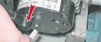
- The VAZ 2106 regulator has two outputs, which are designated “B” and “C”. These contacts are supplied with power from the battery. There are two more contacts that go to the generator brushes. The lamp is connected to these contacts as shown in the figure below.
The sequence for replacing a failed relay regulator
Before starting work, you need to decide what type of regulator is installed on the VAZ 2106: the old external one, or the new internal one. If we are talking about an outdated external regulator, then removing it will not be difficult, since it is attached to the arch of the left front wheel.
If the VAZ 2106 has an internal regulator installed (which is most likely), then before removing it you will have to remove the air filter from the car, since it interferes with access to the generator.
- On the external relay, use an open-end wrench to unscrew the two bolts holding the device on the left wheel arch.
- After this, all wires are disconnected manually, the regulator is removed from the engine compartment and replaced with a new one.
There are a couple of important points that cannot be left out. First of all, there is a problem with external regulators for the VAZ 2106. These are very old parts that have been discontinued a long time ago. As a result, they are almost impossible to find on sale. Sometimes a car owner has no choice but to buy an external regulator in person, using an ad on the Internet. Of course, the car owner can only guess about the quality and actual service life of such a part. The second point concerns the removal of internal regulators from the generator housing. For some unknown reason, the wires connected to the regulator on the generator side are very fragile. Most often they break “at the root,” that is, right at the contact block. Fixing this problem is not so easy: you have to cut the block with a knife, resolder the broken wires, isolate the solder points, and then glue the plastic block with universal glue. This is very painstaking work
Therefore, when removing the internal regulator from the VAZ 2106 generator, extreme caution should be exercised, especially if repairs have to be carried out in severe frost
So, in order to check and change a burnt-out voltage regulator, the car owner does not need special skills. All he needs is the ability to use a wrench and a screwdriver. And basic understanding of how a multimeter works. If all this is present, then even a novice car enthusiast will not have any problems replacing the regulator. The main thing is to strictly follow the recommendations outlined above.
Purpose of the device
The generator voltage depends on the following factors:
- Rotor speeds.
- Current load.
- Magnetic flux values.
A sufficient condition for the generation of electrical energy is the rotation of the rotor of the VAZ 2106 generator in a magnetic field. Magnetic flux crosses the stator windings. AC voltage is generated. The generator diodes rectify the current.
The role of the electromagnet is performed by the excitation winding. It is laid in the grooves of the rotating part. The excitation voltage is supplied to it through the brush assembly. By changing the strength of the current passing through the winding, generation is controlled.
The VAZ 2106 (RR) voltage regulator controls the rotor winding current. The block changes the resistance of the excitation circuit depending on the network voltage level. The generator responds as expected. This way the device returns the generator voltage to normal.
Increased demands are placed on the operation of the control unit. They are determined by working conditions and technical characteristics of consumers. All equipment that is connected to the passenger vehicle network is designed for 12 volts (V). The VAZ voltage regulator must maintain a range from 13.2 to 14.4 V. This gap should not depend on the number of rotor revolutions and ampere load.
The voltage regulator relay should turn on automatically after starting the engine. In addition to its main purpose, the device performs additional functions:
- protects the generator from overloads;
- recharges the battery;
- protects devices from overvoltage.
Proper operation of the PP will protect electrical equipment from overvoltage. Failure to charge will shorten the battery life. Low mains voltage will make it difficult to start a cold engine.
VAZ 2106 car charging diagram
The VAZ 2106 charging circuit consists of a fairly small number of parts:
- three-phase synchronous generator with excitation winding;
- diode rectifier (combined in the same housing with the generator);
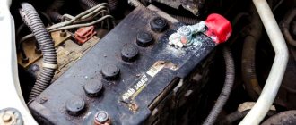
- accumulator battery;
- voltage regulator relay (mechanical or electronic);
- charging indicator lamp relay;
- battery charging indicator light.
The generator is driven from the crankshaft via a V-belt drive. A rectifier built into the generator converts its current into direct current. Next, the voltage regulator relay maintains its value in the range from 13.5 to 14.3 V. Old type relay regulators worked on the principle of mechanical closing and opening of contacts depending on the generator voltage. Such devices required additional adjustments during operation.
The modern VAZ 2106 charging relay circuit includes an electronic voltage regulator, built entirely on discrete elements, and does not require additional intervention in its operation throughout its entire service life. However, the use of such devices requires additional safety measures. Thus, when the engine is running, it is prohibited to remove the terminals from the battery in order to avoid damage to the new model relay regulators.
The warning lamp relay, which provides an indication when the battery charging voltage is lost, is a conventional electromagnetic relay with normally closed contacts. One terminal of the relay coil is connected through the ignition switch to the positive terminal of the battery. The other contact is connected to the +12 V terminal of the generator. The normally closed relay contacts are respectively connected to the +12 V battery (via the ignition switch contacts), and to the warning light.
When you turn the key, battery voltage appears at the relay contacts and the charging lamp lights up. When the engine is running, voltage appears at the output of the generator, which is supplied to the terminals of the electromagnetic relay. When a value of about 7.5 V is reached, the magnetic field of the solenoid increases so much that it attracts the armature, and the contacts through which voltage from the battery is supplied to the charging lamp open. The warning light goes out.
Types of structures
There are 2 types of regulators: old and new. They replace each other, although they contain different fillings. The old design is equipped with a mechanical relay. VAZ cars are equipped with a voltage regulator of the PP-380 type. Devices of this series use moving contacts to switch on resistors.
This spare part has been removed from mass production. Nowadays such specimens are rare. The vibration regulator PP-380 also has a number of disadvantages. Let us point out the difficulties in operating the contact option:
- need for customization;
- step adjustment;
- periodic cleaning of the contact group;
- low reliability;
- creates radio interference;
- short service life.
Device diagnostics
A malfunction of the charging circuit elements can be detected while driving. With the engine running, look at the instrument panel. When the voltage drops, the charging relay turns on the light. The alarm indicates a possible failure of the PP.
To check the voltage regulator, you need a voltmeter. The tester can be purchased at a store or borrowed from a familiar electrician. The mode switch is set to the limit of 20 V. The common wire (black) is connected to the ground of the passenger car, and the red probe is placed on the “+” sign of the battery.
You can check the relay regulator with the engine running and the battery fully charged. The sequence of actions to diagnose the device should be as follows:
- Use the ignition key to start the engine.
- Turn on the load (high beam headlights).
- Warm up the engine for 15 minutes.
- We set the rotation speed to 2.5 thousand using the tachometer.
- We take tester readings at the battery terminals.
After completing all the points, an analysis is carried out. If the needle on the instrument scale is within 14.2 V, then the regulator copes with its task. In this case, the voltage should not significantly depend on the number of revolutions.
Deviation of indicators from the norm indicates a breakdown of the regulator.
Remember that the electronic relay does not allow the terminals to be removed from the battery while the engine is running. This leads to voltage surges and failure of electronic devices.
Charging VAZ 2106
CS generators are equipped with a built-in voltage regulator. The electrical characteristics of the Delta stator, rectifier unit and rotor with slip rings and brushes are similar to those used in earlier generators. A standard pulley and impeller are used, however, no hole is provided for testing.
Electric relay device:
electromagnet - a wire that is wound on a coil with a core of magnetic material;
anchor - a special plate that controls the contacts;
switch (switching, opening, closing).
When an electric current passes through the winding of an electric magnet, an electric field arises, pressing the armature to the core, using a pusher to move it, switching the contacts. There are two main types of autovoltage regulator relays used on Zhiguli 2106 cars.
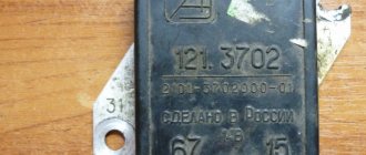
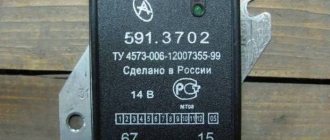
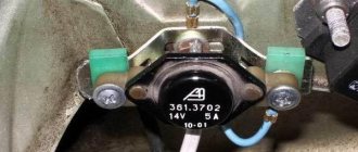
Non-contact electric relay-regulator type 121.3702. A fairly new unit used by drivers these days, which does not require any settings or additional regulation.
The magnetic electric regulator with the index PP-380 is an old-style device, currently its production has been suspended, it is not produced as a part for the VAZ 2106.
The interchangeability of the relay allows you, when changing from one type to another, to not have to modify the electrical charging circuit of the machine.
Before you begin replacing the voltage relay, you need to check the functionality of the regulator. You should start the car, and the crankshaft rotation speed should be 2500-3000 rpm. Then you need to turn off all electrical consumers, except the ignition, and measure the voltage at the battery terminals with a voltmeter.
Missing, reasons
1. Wear of generator brushes
2. Failure of the generator diode bridge
3. Charging relay malfunction
4. Problems with the generator.
The generator won't work
To check the brushes, the generator does not need to be removed from the vehicle, since the brush assembly is accessible and easily removed. Worn brushes are either replaced or the entire assembly is replaced. The movement of the brushes is checked by pressing. The brushes should slide into their wells easily and return easily. Otherwise, the brushes are removed and the wells are cleaned, and burrs are also removed from the brushes themselves.
The contact of the generator with the vehicle ground is also checked and, if necessary, restored. Sometimes it is enough to slightly release the fastening of the wire with ground and move the wire from side to side, which will be enough to restore reliable contact. For complete control, the wire is removed and the tip is stripped.
Connection
We unscrew the 2 fasteners of the charging lamp relay and remove the product from the installed studs.
We mark the supply wiring with a marker or felt-tip pen to control the correctness of the reverse connection of the updated product. If the relay is incorrectly connected to the vehicle's power supply network, it stops functioning, which will create an emergency situation due to a sharp increase in the potential difference at the output contacts of the generator device.
We disconnect the wire circuit, replace the relay with a working product and carry out the reverse installation.
When testing the charging lamp relay, it is strictly forbidden to make a short circuit between the output elements of the circuit, because this will cause defects in the current rectifier unit. Before testing the charge regulator relay, you must ensure that the alternator belt tension is optimal. Other energy resources should not be connected to the electrical circuit of the generator excitation winding, because the voltage drop on the VAZ 2106 charging relay under study may exceed the optimal values.
How to check
Start the car and set the crankshaft speed to 2500-3000 rpm.
Turn off all unnecessary electrical consumers, with the exception of the ignition itself, of course.
Measure the voltage at the battery terminals with a voltmeter. It should be equal to 14.2V plus or minus tenths.
For any significant voltage deviations from the norm, the regulator must be replaced. For this:
Unscrew the two nuts securing the relay and remove the regulator from the studs.
Mark the wires with a marker so that during further assembly you do not mix them up, and this is important, because if you mix up the wires, the regulator will stop working and, as a result, the voltage at the generator output will increase. After disconnecting the wires, replace the regulator with a new one and install in the reverse order of removal. After disconnecting the wires, replace the regulator with a new one and install in the reverse order of removal.
After disconnecting the wires, replace the regulator with a new one and install in the reverse order of removal.
Connecting the unit
Before discarding the device, you should make sure that other parts are in good condition. The belt, alternator, battery, and wires are subject to inspection. The lack of charging of the VAZ 2106 may be caused by a loose belt. If the unit was removed before checking, you should make sure that the wires are connected correctly.
Replacing the voltage regulator is done in a garage. Even an inexperienced driver can do this. You will need a tool, skillful hands and a little knowledge.
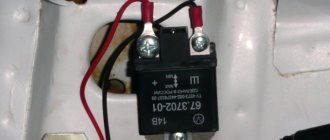
Open the hood to find the remote relay. In the Zhiguli, the box is attached with lugs to the left wing. We find the object near the brake fluid reservoir. Some relays are built into the generator housing. People call them integrals.
Do not rush to remove the wiring from the terminals. Experienced car enthusiasts are advised to first mark the wires with a marker. There are 2 gray and orange wires suitable for the VAZ voltage regulator. They are attached to terminals numbered 67 and 15. Do not mix up the wires. The gray color corresponds to the number 67, and the orange color corresponds to 15.
At the end, a re-check is carried out. Diagnosing and replacing the voltage regulator does not require much effort. It is not necessary to go to a service station. Save yourself the expense of material costs and repair the car yourself.
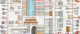
Schematic electrical diagrams, connecting devices and pinouts of connectors
The generator in cars is designed to generate electricity and charge the battery. If the normal operation of a car electric generator is disrupted, the battery begins to discharge and soon the car will stop starting completely - there is not enough battery charge. This device consists of a three-phase diode bridge, which, in turn, has 6 silicon diodes. Electrical voltage is created by the excitation of the rectifier at the moment when the rotor poles change under the stator windings. When the rotor rotates inside the machine stator, the poles of the rotor change. To increase the value of magnetic fluxes, the stator contains an electromagnetic exciting winding in the area of the magnetic cores. Marking and designation of wires:
- P - pink.
- F - purple.
- O - orange.
- B&W - black and white.
- KB - brown and white.
- CHG - black and blue.
- K - brown.
- H - black.
- B - white.
What is a charging relay
The entire electrical system is powered from two sources:
- Battery - with the engine stopped. It is from the battery that power is supplied to the starter windings when the engine starts.
- Generator set - it is designed to power all consumers when the engine is running. But the primary task is to restore the battery’s charge level, since after starting it loses capacity, and significantly.
The battery voltage is always the same - it can only decrease if charging is not performed.
But a car generator can produce voltage in the range of 10-30 Volts. This is a large range; the electrical system will not be able to cope with such differences. It is the VAZ-2106 charging relay that allows you to stabilize the voltage and prevent overvoltage.
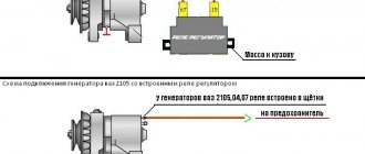
Connection diagram for the VAZ-2101 generator
Structurally, generator 2101 consists of the following main elements:
- The rotor is a moving part that rotates from the engine crankshaft. Has an excitation winding.
- The stator is the stationary part of the generator and also has a winding.
- Front and rear covers , inside of which bearings are installed. They have eyelets for attaching to the internal combustion engine. The back cover contains a capacitor necessary to cut off the alternating current component.
- Semiconductor bridge - called a “horseshoe” for its similarity. Three pairs of semiconductor power diodes are mounted on a horseshoe-shaped base.
- A pulley on which the VAZ-2101 generator belt is placed. The belt is V-shaped (on modern cars a multi-ribbed belt is used).
- The voltage regulator is installed in the engine compartment, away from the generator. But still it must be considered part of the structure.
- The brushes are mounted inside the generator and transmit the supply voltage to the field winding (on the rotor).
Generator VAZ 2106: purpose and functions
Charging relay for VAZ 2107
A car generator is a small electrical device whose main task is to convert mechanical energy into electrical current. In the design of any car, a generator is needed to charge the battery and feed all electronic devices while the engine is running.
The generator's task is to ensure uninterrupted operation of all electrical systems of the machine and the battery.
How exactly does the generator work on a VAZ 2106? All processes of energy conversion from mechanical to electrical are carried out according to a strict scheme:
- The driver turns the key in the ignition.
- Immediately, the current from the battery through the brushes and other contacts enters the excitation winding.
- It is in the winding that the magnetic field appears.
- The crankshaft begins to rotate, from which the generator rotor is also driven (the generator is connected to the crankshaft by a belt drive).
- As soon as the generator rotor reaches a certain rotation speed, the generator enters the self-excitation stage, that is, in the future, all electronic systems are powered only from it.
- The generator performance indicator on the VAZ 2106 is displayed in the form of a control lamp on the dashboard, so the driver can always see whether the device has enough charge for full operation of the car.
Standard device for the "six"
Design of the G-221 generator
Before talking about the design features of the VAZ 2106 generator, it should be clarified that it has unique clamps for mounting on the engine. On the body of the device there are special “ears” into which studs are inserted and tightened with nuts. And so that the “ears” do not wear out during operation, their internal parts are equipped with a high-strength rubber gasket.
The generator itself consists of several elements, each of which we will now consider separately. All these devices are built into a light-alloy cast housing. To prevent the device from overheating during long-term operation, the case has many small holes for ventilation.
The device is securely fixed in the engine and connects to various car systems
Winding
Due to the fact that the generator has three phases, windings are installed in it immediately. The purpose of the windings is to generate a magnetic field. Of course, only special copper wire is used for their manufacture. However, to protect against overheating, the winding wires are covered with two layers of heat-insulating material or varnish.
Thick copper wire rarely breaks or burns out, so this part of the generator is considered the most durable
Relay regulator
This is the name of the electronic circuit that controls the voltage at the output of the generator. The relay is necessary to ensure that a strictly limited amount of voltage reaches the battery and other devices. That is, the main function of the relay regulator is to control overloads and maintain an optimal voltage in the network of about 13.5 V.
A small plate with built-in circuitry to monitor the output voltage
Rotor
The rotor is the main electric magnet of the generator. It has only one winding and is located on the crankshaft. It is the rotor that begins to rotate after the crankshaft starts and gives movement to all other parts of the device.
The rotor is the main rotating element of the generator
Generator brushes
The generator brushes are located in brush holders and are needed to generate current. In the entire structure, it is the brushes that wear out the fastest, since the main work of generating energy falls on them.
The outer side of the brushes can quickly wear out, which is why there are interruptions in the operation of the VAZ 2106 generator
Diode bridge
A diode bridge is most often called a rectifier. It consists of 6 diodes that are placed on a printed circuit board. The main job of a rectifier is to convert alternating current into direct current to maintain stable operation of all electronic devices in the car.
Due to its specific shape, drivers often call the diode bridge a “horseshoe”
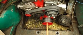
Pulley
The pulley is the driving element of the generator. The belt is tensioned simultaneously on two pulleys: the crankshaft and the generator, so the operation of the two mechanisms is continuously interconnected.
One of the generator elements
Connection diagram for the VAZ-2107 generator
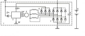
1 - battery; 2 - negative diode; 3 - additional diode; 4 - generator; 5 - positive diode; 6 - stator winding; 7 - voltage regulator; 8 — rotor winding; 9 — capacitor for suppressing radio interference; 10 — mounting block; 11 — battery charge indicator lamp in the instrument cluster; 12 - voltmeter; 13 — ignition relay; 14 - ignition switch.
Connection diagram for the VAZ-2108 generator
The VAZ-2108 generator has a rather massive stator winding, since it uses a large cross-section wire. It is with its help that electricity is generated. The wire is wound evenly over the entire inner surface of the stator into recesses specially provided for this purpose in the magnetic core. It’s worth talking about the latter separately. The middle part, the generator stator, consists of a series of thin metal plates pressed tightly together. They are often boiled on the outside to prevent separation.
Connection diagram for the VAZ-2109 generator
- Alternator. The 37.3701 or 94.3701 series can be installed.
- Negative diode.
- Additional diode.
- Positive diode.
- Alternator warning lamp, also known as battery discharge lamp.
- Instrument cluster.
- Voltmeter.
- Relay and fuse box located in the engine compartment in the compartment between the engine and the vehicle interior.
- Additional resistors built into the fuse mounting block.
- Ignition relay.
- Egnition lock.
- Accumulator battery.
- Capacitor.
- Rotor winding.
- The voltage relay is located in the engine compartment.
Connection diagram for the VAZ-2110 generator
On VAZ-2110, 2111 and 2112 cars, a 94.3701 generator was installed with a maximum output current of 80 Amperes and a voltage = 13.2–14.7 Volts.
Here is a breakdown of the connection diagram for the generator on the ten :
- Battery 12V;
- generator 94.3701;
- mounting block;
- egnition lock;
- battery charge indicator lamp in the instrument cluster
Signs of LV malfunction
In VAZ-2110 cars, the voltage regulator breaks quite rarely, but if this happens, signs of its malfunction may be:
- Failure of the control panel backlight.
- Exceeding the battery charging voltage.
- Insufficient battery charge voltage.
If the voltage regulator relay of the VAZ-2110 breaks down, the fuses responsible for the safety of the power supply circuit of the instrument panel may blow out. If the backlight lamps do not light up when the ignition is turned on, there is a possibility that the LV is to blame.
The same can be assumed when the voltmeter needle, indicating the battery charge level, deviates from its usual position, i.e., shows higher or lower voltage.
How to check the generator yourself
How to check a VAZ generator using the example of model 2109. Generator type 94.3701 alternating current, three-phase, with a built-in rectifier unit and an electronic voltage regulator, right-hand rotation.
Generator connection diagram . The voltage to excite the generator when the ignition is turned on is supplied to terminal “D+” of the regulator (terminal “D” of the generator) through indicator lamp 4 located in the instrument cluster. After starting the engine, the excitation winding is powered by three additional diodes installed on the generator rectifier block. The operation of the generator is controlled by a warning lamp in the instrument cluster. When the ignition is turned on, the lamp should be on, and after starting the engine, it should go out if the generator is working. If the lamp is brightly lit or glows half-lit, it indicates a malfunction.
The “minus” of the battery should always be connected to ground, and the “plus” should always be connected to the “B+” terminal of the generator. Failure to turn the battery back on will immediately cause increased current through the generator valves and damage them.
It is not allowed to operate the generator with the battery disconnected. This will cause short-term overvoltages to occur at the “B+” terminal of the generator, which can damage the generator voltage regulator and electronic devices in the vehicle’s on-board network.
It is prohibited to check the functionality of the generator “for spark” even by briefly connecting the “B+” terminal of the generator to ground. In this case, significant current flows through the valves and they are damaged.
Replacement and removal of the electric generator
The generator on a VAZ car is removed either for complete replacement in case of failure or to carry out repair work to replace faulty parts. To perform dismantling, prepare a standard set of tools; it is advisable to drive the car into the inspection hole.
- Disconnect the battery.
- Remove the protective rubber cap from terminal “30” and unscrew the nut and remove it from the wire stud.
- Disconnect the block with wires from the generator connector.
- We loosen the tightening of the generator to the adjusting bar, then lift it all the way up to the cylinder block and remove the belt from the pulleys.
- Completely unscrew the bolt securing the adjusting bar to the cylinder block, then from the bottom of the car unscrew the 2 bolts securing the lower bracket to the block and remove the generator, pulling it out of the engine compartment.