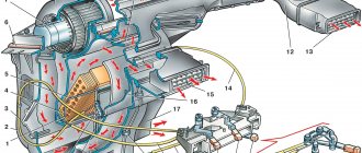
The amount of electronics in modern cars is growing every year, which means that wires are practically everywhere. To ensure that they do not interfere with the operation and stylish interior of the car, they are tied and placed in special channels along the sides, ceiling and floor of the car, and covered on top with finishing panels, carpeting and upholstery.
These wiring harnesses run through narrow channels and are often subject to vibration and mechanical stress, which can cause one or more of them to fail. When this happens, all equipment that is powered by the damaged wire stops working. To cope with the problem, a car enthusiast must know how to test the wiring in a car with a multimeter to quickly and effectively restore its functionality.
How to use a multimeter in a car: detailed instructions for dummies
Hi all! I think many motorists and just electricians will agree that having a multimeter is very helpful in everyday life. It can be useful in everyday life and when servicing or repairing a vehicle. Therefore, today we’ll talk a little about how to use a multimeter and do it correctly.
You can call the device a tester, a multimeter (MTM) or a tester. Although a tester and an MTM are not exactly the same thing. But I suggest that you don’t get hung up on notations, but simply talk about the current topic.
Using such devices, you can check voltage parameters, the operation of electrical equipment, and measure current and resistance. In general, MTMs are multifunctional devices and should be in every driver’s car.
Replacing car wiring
When replacing wiring in a car, be sure to turn off the power, including disconnecting the battery. Of course, this is not a precaution against electric shock, but protection of the vehicle’s electrical equipment from possible short circuits that may occur during repair work.
Sometimes the replacement can be completed in 10-15 minutes - for example, if the wires of the “battery-generator” supply circuit are damaged. If the integrity of the wiring in the cabin is damaged, there are problems with grounding, or a short circuit in the on-board computer circuit, then the work will take much more time. And the main thing here is not to make a mistake, since incorrectly connecting the wires (for example, if the polarity is reversed) can cause a short circuit, damage to expensive electrical equipment and even a fire. If you do not have experience in electrical engineering and electrical installation work, it is better to contact a specialized service for the services of a professional auto electrician.
Source
Getting to know your device
To begin with, I propose to talk about multimeters themselves as electronic devices. Next, detailed instructions will be presented for beginners or, as they say, for dummies.
Let's look at the front panel of the device for measuring indicators in the car and at home. Typically, several values are indicated on the front. Namely:
As for the 3 connectors. The probes are connected through them. The set with pliers is included with the MTM, so everything should be clear here.
There is one note regarding how and when to connect certain probes to the tester. There is a black wire that invariably always goes into the socket that is marked with the symbols COM.
But with red the situation is more complicated. It all depends on what kind of measurements you are going to take with your digital multimeter. When making measurements of mains voltage, resistance or current up to 200 mA, then you only need the VmA output. If the value exceeds 200 mA, then connect the red probe to 10 ADC.
I think we've sorted this out. If you do the opposite, you will not be able to use the tester for a long time. The reason for this will be a blown fuse. As in the case of the cigarette lighter fuse in a car, fusible elements are also used here.
Analog MTM
Most motorists and electricians prefer digital multimeters. These are modern devices with wide functionality.
But there are also outdated devices on the market. They are called analog or pointer. Whichever is more convenient for you. But their characteristics and efficiency are significantly inferior to digital solutions. Using a pointer tester is not the best option, since the scale has a larger error.
And in general, using such devices is not particularly convenient. It is better to immediately switch to good quality digital devices.
I would include the following models as such:
What is a short circuit? Its consequences
Short circuit occurs in sockets, plugs, junction boxes and other places where there is a connection of wires. The reason for everything is poor quality contact. It leads to an increase in load and, as a result, to heating. Most often, the result is burnout of the insulation, as a result of which the supply wires become short-circuited with each other.
A short circuit is very dangerous for humans and in most cases causes a fire. In this regard, it is necessary to determine its location quite quickly.
In order to prevent short circuits, it is necessary to periodically test the power cable lines with voltage, which will avoid serious consequences.
Instructions for use
Now I’ll tell you in a little more detail about how to use a digital multimeter with your own hands to make different measurements of parameters.
In our material we will consider the measurement:
To make everything more clear, I will tell you about each procedure separately. If you have anything to add to this instruction, be sure to write in the comments.
Voltage
Measuring the voltage yourself is not difficult. But detailed instructions for such a case will definitely not hurt.
The sequence of your actions will be like this:
You can clearly see that there is nothing complicated in this procedure. Therefore, you can easily measure the voltage that is currently observed in the electrical network with your own hands. Both variable and constant.
The main thing here is not to touch the probe with your bare hands, since it will be under the influence of current.
Current strength
To determine the current parameters, the first step is to answer the question of what kind of current flows through the wiring. It can be variable or constant.
Next, you look at the equipment or device to see what the approximate value may be. The indicator is measured in Amperes, that is, denoted by the letter A.
And here, as you can see, you can easily cope on your own. The task of measuring the current strength is completed. Therefore, let's move on to the next point.
Resistance
The simplest and safest measure using MTM is resistance measurements.
Here proceed as follows:
Following these simple rules and consistency in your actions will allow you to quickly and without any problems carry out all the necessary procedures for measuring resistance.
A good multimeter function that often comes in handy when repairing home appliances. For example, I recently fixed my wife’s iron. And the tester turned out to be extremely useful in this work.
Calling
I didn't tell you anything about the back panel of the multimeter. Although there are several more functions there. They are mainly intended for radio technicians who are professional in their work. They will not be needed for tasks at home or when repairing a car.
With the exception of one mode. It is called dialing mode. It is designed to search for breaks in electrical circuits. To do this, the chain needs to be ringed. When it is closed, that is, there is no break, then a sound signal appears. If there is a break, then no sounds will appear. This means that you have found the problem area.
To check, you need to place two probes on both sides of the chain being called. This allows you to find even a minor break in an extended electrical circuit.
I tried to help as best I could. You have comments and questions. Additionally, you can watch a visual video.
I think everyone, if desired, can easily understand the operation of any modern digital multimeter. In addition, the manufacturer always includes detailed instructions for the device. Therefore, you should always start working with the device by studying the instruction manual.
Source
Multimeter and battery
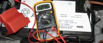
It happens that the incorrect functionality of the battery is obvious. A multimeter comes to the rescue here too. Having picked it up and set it up to measure current, you need to:
First we disconnect one terminal, then we connect the red contact to the positive value. Accordingly, black goes to minus. A normal voltage reading is considered to be between 12.4 and 12.8 V.
Remember! Measurements are taken no earlier than an hour after the engine is turned off.
You still need to measure the voltage under load. This means that it should be equal to a figure twice as large as the capacity.
This means that if the capacity is, say, seventy-five A/hour, the corresponding load should be one hundred and fifty amperes. A voltage drop below nine indicates a battery malfunction. This may also indicate that the battery is undercharged. When you disconnect the load, the voltage usually returns to normal within seven seconds.
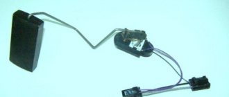
By the way, it is better to carry out wiring diagnostics armed with a diagram of the electrical equipment of your car.
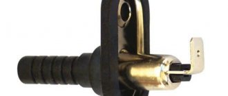
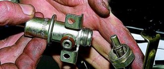
Features of the probe and its operating principle
The continuity probe is structurally a plastic capsule, inside of which a resistor with a high resistance is placed. A metal rod extends from the plastic base, the end of which is used for direct contact with the contacts of electrical equipment. The device shows the presence of voltage; green and red LED lights located on the plastic case act as indicators. The green LED indicates low circuit resistance, the red LED indicates the presence of voltage.
A car test probe, which is essentially a voltmeter, is indispensable when identifying faults in a car's electrical equipment, as well as when installing new electrical equipment on a vehicle.
The diagnostic device makes it possible to determine the integrity of an electrical circuit or a separate section of it, identify locations of broken connections, unreliable contacts, the location of failed parts, as well as identify a number of other damages. To carry out a quick check of current-carrying equipment, the use of a continuity probe is the most rational and expedient solution.
Automotive probe for checking the ignition spark JTC
Automotive probe for checking the ignition spark TEST-M
Automotive probe 6-24V 110mm “needle” brass AVTODELO
Automotive tester 6-48V in a FORSAGE bag
Automotive probe 6-24V 120mm “needle” TECHNICIAN
Car probe for checking the ignition spark 0.5m FORSAGE
Automotive probe 6-24V ROCKFORCE
Automotive probe 6-24V 120mm plastic case SPARTA
Automotive probe for checking the ignition spark FORSAGE
Automotive probe 6-24V FORSAGE
Checking the electric heating element
You can also ring an electric water heating element with a multimeter. To do this, the probes of the device must be attached to the contact plates of the heating element. If the resistance reading is small, then the heating element is working. With very large values or one (depending on the model), the heating element is damaged and requires replacement.
Note! Sometimes one housing may contain two heating elements connected to voltage in parallel. In this case, you need to ring them separately, having first removed the jumper between them
It is very important for boilers and other water heating devices to ring the contacts of the heating element for penetration into the body. To do this, the probe is connected to one of the contacts, and the second - to the body of the heating device
If the tester shows a certain value, the internal insulation has been damaged in this heating element. To prevent electric shock, the heating element must be replaced.
The use of a continuity probe for testing various types of electrical equipment
Battery check
Using a probe, you can check the presence of voltage at the battery terminals. To do this, using an alligator clip, you need to connect to the battery terminal with the “-” sign, and attach the end of the probe to the terminal with the “+” sign.
Checking the fuse
To check the fuse, touch one end of its terminal to the positive terminal of the battery, and the end of the probe to its second terminal.
Checking the incandescent lamp
To check an incandescent lamp with a continuity probe, place one terminal of its base to the positive terminal of the battery, and attach the end of the probe to the second. When testing a light bulb with two filaments (such as a car headlight bulb), test them one at a time.
Checking a car relay
In addition to the electromagnet winding, an automobile relay also has contacts that, over a long period of operation, can burn out and, as a result, stop switching electrical circuits. Using a continuity probe, you can check both the integrity of the electromagnetic winding and the serviceability of the contacts.
To check the relay winding, you need to attach one of its terminals 85 or 86 to the battery terminal with the “+” sign, and attach the end of the probe to the second terminal. The serviceability of the contacts is determined by touching the terminal of the moving contact 30 to the terminal, and by touching the terminal 87a with a continuity probe.
In the same way, any microswitches and switches are checked.
Checking new wiring
The serviceability of the new power supply system is checked for short circuits. Problems can be avoided if you purchase high-quality wires and a residual current device. If in doubt, check the quality of the insulation when purchasing in a store.
The electrical network (wiring) of modern cars is single-wire, the second conductor is “ground” - the car body and the engine. During the operation of the vehicle, you may encounter some wiring faults (for example, a short circuit or break). Next, let's look at the instructions on how to find them yourself.
All electrical circuits (except for the starter and generator power circuits) are protected by fuses. And the power circuits of powerful electricity consumers (headlights, power windows, heated mirrors or seats, etc.) are switched through a relay. Therefore, you should start troubleshooting the electrical wiring in the following sequence:
- if a lighting device does not work (for example, a headlight or a lampshade), then first we check whether the lamp has burned out;
- check the serviceability of the fuse;
- check the serviceability of the relay;
- check the reliability of the contacts in the circuit connectors (they may oxidize, in which case they need to be cleaned).
It is also recommended to check all ground attachment points.
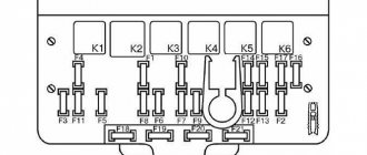
Relay and fuse diagrams for LADA cars:
Advantages of using a test probe
Diagnostic equipment of this type is distinguished by its functionality and ease of use. Due to a malfunction of electrical equipment, all components of the vehicle may fail. The probe allows you to quickly identify the cause of the malfunction, determine the circuit elements that need to be repaired or replaced, and also make repairs or replacements with the creation of the correct electrical circuit.
A car test rod is an inexpensive device that should be in the toolkit of any car owner.
Driving for a long time leads to fatigue of the neck muscles and harms the health of the spine. Headrest pillows help solve these problems. Find out about what headrest pillows are and why they are needed, as well as about the range, selection and use of these accessories - from the article.
To cut external threads using round and rectangular dies, you must use a special device - a die holder or a die driver. Read all about the knobs, their existing types, design and characteristics, as well as the selection and use of these devices in the article.
Threaded fasteners are simple and reliable, but damage to the bolt or stud may make it impossible to remove and replace. This problem can be solved using a special tool - a set of extractors. Read about these devices, their types, design, selection and application in this article.
Feeling the breath of winter, all motorists are thinking about replacing seasonal tires. And many of us, when buying winter tires, are faced with a difficult choice - “studded” or “Velcro”? Each type of tire has its own advantages and disadvantages, and choosing one over the other can be very difficult. In this article we will try to make this difficult choice.
Filling the tank with low-quality diesel fuel can damage the engine until it completely fails. Special auto chemicals—diesel fuel additives, which are described in detail in this article—help to minimize or eliminate the negative consequences of refueling with low-quality diesel.
Using the right type of tires ensures your car has stability and controllability in any driving situation. Only seasonally used tires guarantee optimal grip on the road surface and minimal braking distance.
In addition to the main direction indicators, all motor vehicles must have auxiliary lights - side turn signal indicators. Read all about repeaters, their classification, design, characteristics and operation, as well as about the selection and replacement of this type of device.
Source
How to repair car electrical wiring?
Faulty vehicle wiring leads to serious problems during the operation of the car - from incorrect operation of sensors and devices, on-board computer and automation to complete failure of expensive electrical equipment. Remember that a short circuit in the on-board circuits can lead to a fire in the vehicle. Therefore, faults in electrical equipment and electrical equipment should be eliminated immediately when they are detected - there is no need to put off repair work “on the back burner”.
You can repair car electrical wiring either yourself or at a car service center. The main difficulty lies in finding faults - breaks, failed relays, fuses and blocks, breakdowns of individual elements and auto electrical devices.
Tags: multimeter, probe.
Comments 70
In general, I don’t trust purchased probes made from the body of a cigarette lighter plug... I have my own “eternal” probe scheme, which has never failed. two diodes, two LEDs, two resistors, and a 4-6 volt battery from an autonomous siren
About the oxidized and destroyed wire inside the insulation:
The question is how to find out the reference resistance of the wire, given that the terminal contacts are 1 ohm each (=2 ohms)? ... I’m sitting here scratching my head. I’ll be very glad to help. In a jeep, on the floor, wires go in a bunch, from the hood, under the car, to the gas tank and level sensor. The total length is about 5 meters (maybe more) How to ring them, assembled? To understand where the sausage is, in the terminal blocks, or the wires themselves? And if you pierce sections of wires, what is the best way to seal them so that they do not collapse? … Thanks in advance.
Only with light bulbs can the field assembly in the module be burned. You have to be careful with them.
Not everyone in the comments admired it, I immediately said that he was bullshit and gave an example that because of the fuse block only 10V was coming to the pump, and this crap would show that there is voltage.
I meant the overwhelming majority, those who are not in the subject.
I completely agree with every word you wrote.
One old auto electrician showed the starter of a ZIL. I took a light bulb with one cut wire and actually connected it in series with ground and the stator windings, smoke appeared in the place of weak insulation, insulated the winding, checked it again - the norm. Then, in series with the ground and the brush assembly, a microcrack filled with coal dust was discovered in one of the insulators, also sparking and smoke, replace the insulator, control check - the norm. Of course it’s a violation of TB, but you can foolishly tighten a nail with a screwdriver. I used it myself and it helps.
Among the instruments, the auto electrician did not see a 220 V 80-100 W light bulb with a break in one wire for diagnosing starters to determine the point of short circuit (brush assembly, etc.) to ground. Is this option available?
There were no problems with the starters, or with their diagnostics. And I didn’t know this method, can you tell me more?
An excellent sample, I’ve already erased about thirty of them)) I use them as a consumable. One minus: 24V batteries explode, they don’t last long. You just need to approach any testing by a tester headlong.
Each tool has its place in the work. You need a multimeter, a tester, an LED, and a postulograph.
Source
High-voltage wires VAZ 2115
Automotive high-voltage (HV) wires play an important role for internal combustion engines, since they help transmit high current from the ignition coil to the spark plugs. The serviceability and efficiency of the wires determines the timeliness and intensity of ignition of the fuel-air mixture, and therefore the correct and uninterrupted operation of the engine. Despite their simplicity, wires have many different “sores” and can cause a lot of troubles to their owner, which in one way or another will affect his nerves and pocket.
Connection
The order of connecting high-voltage wires must be strictly sequential, since each cylinder of the engine corresponds to a specific socket on the ignition module. Considering that there is a numbering of the sockets on the ignition module body, the risk of confusing anything is minimal.
The procedure for connecting high-voltage wires of the VAZ 2114 injection type depends on the year of manufacture of your car. Fourteen cars before 2004 had 4-pin ignition modules installed, and cars after 2004 had 3-pin coils.
The connection diagram for VAZ 2114 high-voltage wires to the ignition module (until 2004) is as follows:
Connection diagram for VAZ-2114 with ignition coils (after 2004):
In the pictures you can see the numbers of the landing slots. Each number must have a corresponding cylinder connected to it (cylinder numbering is counted from left to right).
To correctly install high-voltage wires on the VAZ 2114, follow the following algorithm of actions:
— Turn off the ignition. Open the hood and remove the power terminals from the battery;
— We remove the old GDPs from the mounting sockets on the module and cylinders;
— We remember the location of the high-voltage wires of the VAZ 2114 and connect new GDPs according to the diagram. Before replacing, it would not be amiss to draw this very diagram by hand on paper so as not to confuse anything;
— We connect power to the battery and, to check whether we did everything correctly, start the engine.
When installing the wiring, do not try to connect individual air intakes to each other with plastic clamps; to do this, you must use the comb holder that comes with them. A thin clamp can easily wear through the insulating coating. Also make sure that the GDP does not bend.
Connecting armored wires on VAZ 2115 and 2113 is carried out in a similar way.
How to remove high-voltage wires?
Turn off the ignition. Open the hood. Pull out the wires from the ignition module and from the engine.
How to connect high voltage wires?
The BB wires must be connected in a certain order. Each wire goes to a specific cylinder and to a specific connector in the ignition module (ignition coil). There are markings both on the wires and on the ignition module. But without removing the module, the markings cannot be seen, so see the photo below.
Connection diagram for high-voltage wires:
Cylinder numbering from left to right. Ignition module numbering: first cylinder - lower left compartment of the ignition module
Second cylinder - upper left compartment
The third cylinder is the upper right,
The fourth cylinder is the lower right compartment of the ignition module.
Location
Incorrect installation and location of high-voltage wires can lead to a spark jumping from wire to wire or to ground, which, in turn, can lead to misfires and a decrease in the crankshaft speed when the car is moving at high speed.
Therefore, install the high voltage wires properly as shown in the pictures above.
Disconnect the high-voltage wires from the spark plugs and ignition coils. Clean and check the integrity of the insulation of high-voltage wires. Check the internal contact surfaces of high-voltage wires for corrosion or carbon deposits.
Use an ohmmeter to measure the resistance of the high-voltage wires.
How to test the wiring in a car yourself with a multimeter
People have long lived surrounded by electrical appliances, which have quietly entered the life of every person since childhood. Electronic watches, electric kettles, telephones, computers, cars are indispensable human assistants in everyday life and at work. But sometimes devices break down and you have to check and repair them. There is nothing difficult about this if you know how to use measuring instruments and know, for example, how to test the wiring in a car with a multimeter or how to check the integrity of an electrical circuit.
What you need to know about the multimeter
The model of the multimeter does not matter much, but it is desirable that it have a dialing function. The handle of the tool is installed on the dial. When connecting the probes and closing the working contacts, a sound signal will be heard. Such a signal is not required in the device. A break in a hidden or open electrical circuit will be signaled by a unit on the scale.
You can also check hidden wiring in the wall. If there is no damage, the tester will show resistance. In small household networks it should be closer to zero values.
General information
If a connection is found, then if there is a built-in speaker, the device emits a sound signal. This is where the term “call” comes from. The device rings if there is a connection. A multimeter can also indicate that there is no connection between elements and helps determine a short circuit. Using the tester, all kinds of radio components are checked: resistors, transistors, diodes, relays, capacitors, and so on.
Conductor continuity is based on Ohm's law for a section of an electrical circuit. Ohm's law states that the resistance of an element is equal to the ratio of the applied voltage to the magnitude of the current in a section of the electrical network. Resistance is measured in Ohms. A resistance of one Ohm indicates that a current equal to one Ampere flows through the conductor at a given voltage of one Volt. Based on the calculated data on resistance, conclusions are drawn about the results of the call.
That is, a certain voltage is set on the multimeter, and the current value is determined using the instrument scale and the resistance is calculated. In other words, the multimeter is a voltage source and an ammeter to measure the resulting current.
Sequence of actions when checking wiring
Let's take a closer look at how to check the wiring in an apartment on your own. You can call it in several stages:
- set the multimeter knob to the “continuity” position;
- Insert the ends of the measuring wires into the sockets of the device;
- turn on the multimeter;
- short-circuit the measuring leads and release them;
- on the wire being tested, strip the ends and touch them with the measuring contacts of the device.
The black wire is inserted into the COM socket, which in some devices is marked with a “*”. Red – to socket Ω. Sometimes it is indicated by the sign R. If the wires are swapped, this will not affect the results of the integrity test. If everything was done correctly, a sound signal will sound when closed. The same signal will sound when conductor integrity is detected. The display will show 0. The appearance of one and the absence of sound is evidence of damage to the wire.
Checking the integrity of the insulation
To check the insulation condition of the cable cores, it is necessary to determine whether there is a short circuit between them. If it is not present, the insulation is good, the indicator shows one, and there is no sound signal. If a signal appears, then this is a sign of insulation failure and the appearance of a short. The cable must be disconnected from the electrical network, since it has been detected that there is a circuit between the phase conductor and grounded installations or zero.
Device structure
Devices may differ in appearance, but multimeters are fundamentally divided into analog devices and digital devices.
Analogue devices are already gradually being replaced from the market by digital ones, but in the homes of many home craftsmen you can still find analog devices.
Such devices are equipped with an indicator screen with a scale and arrow. The advantage of these models is the clarity of display of measurements. The deflection of the needle is visually easier to assess than the flashing of numbers on the electronic display of digital instruments. Often, when making a call, it is necessary to evaluate approximate resistance indicators or, in general, its presence or presence, so analog devices are suitable for most practical work.
Digital multimeters have more complex electronics and a digital display. This type of device is used mainly in production and industry.
The housings of all multimeters have outputs for two probes. These are two insulated wires ending in needle-like metal tips. In some cases, special clips, so-called “crocodiles,” are put on the nozzles. When choosing a device, you need to pay special attention to the quality of the probes. The correctness of measurements depends on them.
The wires must be flexible with strong soldering and fit well into the device sockets. It often happens that outwardly spectacular probes are of unsatisfactory quality and have poor technical characteristics.
How to check an antenna cable with a tester?
How to check
antenna with a tester (
multimeter
) For this,
a multimeter
(tester) is used to measure the resistance between the braid and the central core of the wire. A value of several tens of ohms is considered a normal value. If it is greater than or close to “0”, a break or short circuit has occurred.
Interesting materials:
Where is the Google Recycle Bin? Where is my Google photo? Where are your contacts on Google? Where are the extensions in Google Chrome? Where was Google's headquarters located? Where is the archive in Google mail? Where is Google's head office located? Where is the Google Chrome browser cache located? Where is the Google Chrome cache located? Where is the Google Chrome cache located?
Operating principle
The analog type of the device does not require its own power supply .
Its operating principle is the same as that of an ammeter, and an analog device works best in the range of radio waves and electromagnetic fields. There are induction coils inside the device body, and when the probes touch the conductor, a current begins to form in the coils. The created magnetic field deflects the indicator needle to a certain angle. The magnitude of this angle depends on the strength of the current generated, and the arrow on the drawn scale indicates the measurement value. Digital devices contain a textolite printed circuit board on which a digital chip , which is responsible for processing the received data. To operate the electrical circuit and screen, digital devices are powered by batteries or an external power source.
Digital multimeters have lower measurement uncertainty and are more accurate than their analog counterparts.
There is a switch on the front panel of the multimeter that selects the measurement mode. The switch sets the scale factor that determines the value on the device scale.
Analog instruments have two types of scale:
The uniform scale is very sensitive to overloads, so the switch is first set to a large scale factor value, which is gradually reduced. The logarithmic scale does not have this drawback and has a range of values from zero to infinity.
Thus, the main components of multimeters are:
What should be the resistance of high-voltage ignition wires?
In order to obtain the most complete information about the serviceability or malfunction of a high-voltage wire, a method of measuring its physical parameters is used.
The simplest electrical measuring tool that should be in the trunk of any car is a multimeter. A simple small multimeter made in China is a little larger than two matchboxes in size and costs about 300 rubles.
In high voltage wires, two main parameters are checked: the resistance of the current-carrying conductor
and
insulation resistance
. The second parameter cannot be measured using a conventional multimeter; for this you need to have an expensive megohmmeter, since the insulation resistance must be several hundred megohms.
The resistance of the center conductor should be in the range from zero to several kiloohms. This depends on the type of high-voltage wires and the presence of limiting resistance in the ignition system.
Limiting resistances began to be used when cars began to be equipped with radio receivers. They significantly reduce the level of radio interference. In addition, they have another important function of protecting the ignition coil and control circuit from breakdown in the event of an overload in the high-voltage circuit. This is possible if the spark plug has a short-circuiting deposit, as well as if a high-voltage wire breaks down on the car body.
In many cars, limiting resistances are placed in a slider; in some cars, spark plugs have a limiting resistor. Sometimes resistors are inserted into the spark plug caps. But most cars use distributed resistance inside high-voltage wires.
In other words, the current-carrying core of a high-voltage wire is made of a conductor with high resistivity:
- nichrome, an alloy of nickel and chromium;
- cotton threads impregnated with a soot solution with a resistance of about 20 kOhm/meter;
- polymer conductive material with a resistance of about 15 kOhm/meter;
- fiberglass coated with graphite.
Sometimes such a conductor has the shape of a spiral, as in electric stoves.
To check high-voltage wires, the multimeter must be switched to resistance measurement mode at a limit of 20 kOhm. Next, connect the probes of the device to the opposite terminals of the wire.
The measured resistance should not exceed a resistance of 20 kiloohms (usually this value ranges from 500 to 3000 ohms). For ignition wires with distributed resistance, its value depends on the length of the high-voltage cable.
Continuity of wires
Before starting any measuring work, it is imperative to check the serviceability of the tester itself.
It happens that the measuring system itself is faulty. To check, the ends of the probes of the measuring device are in contact. If the device is operational, the indicator will display zero or deviate slightly. A slight deviation indicates that the probes and terminals have their own small resistance.
If the multimeter has a sound signal, then the device is set to buzzer mode. This is done by placing the switch on the corresponding icon on the tester body.
The probes are brought to the ends of the part being tested.
Possible tester behavior options:
When taking measurements with a multimeter, do not allow the human body to come into contact with probes and wires where there is no insulation.
Reasons for broken wiring
One of the most common breakdowns is a break in the electrical wiring of a machine, when electric current does not pass through the wire due to a fracture or oxidation of its contacts. Outwardly, this manifests itself in periodic or complete failure of devices or equipment connected to this wire. Sometimes the operation of the system is restored when the section of wiring where the integrity of the contact has been broken is moved. There are several reasons that result in a break in the car wire:
- mechanical rupture of the wire or its attachment point under load, as a result of vibration or rubbing against solid elements;
- oxidation and corrosion processes;
- poor quality conductor material;
- sparking due to poor contact;
- short circuit due to damaged wiring, moisture or other reasons.
Sometimes it happens that with constant vibrations that accompany engine operation, the insulation of the wires even rubs against the protective corrugation. To troubleshoot a problem, you need to be able to accurately determine which wire is broken and where it happened, since there are many of them in the car's electrical system.
Troubleshooting in a car's electrical circuit
If some component in the car does not work, then first of all you need to check the electrical circuit. There are no particular differences between how to test different wires in different cars with a multimeter, except for the high-voltage cable.
First, make sure that there is voltage in the circuit of the non-working unit:
If the tester indicator shows the presence of voltage, it means the wire is intact. By analogy, all wires of the node are called. If the wire is damaged, the multimeter scale shows zero.
It must be taken into account that in some areas of the car voltage is supplied only when the ignition key is turned on.
When the voltage check is completed, the current value is checked. The device is switched to ammeter mode, the switch selects a measurement range of up to ten amperes. All vehicle devices must be turned off and the tester must be properly connected to the vehicle's electrical network. To do this, a multimeter is connected between the positive terminal of the battery and the unit being tested. The device screen should display the found current value; it should correspond to the consumption of constantly switched on devices of the machine. If the current value exceeds the norm, a conclusion is drawn about its leakage.
In this case, they begin checking devices that are not included in the standard equipment of the car, and places where wiring is part of moving mechanical components.
Experienced craftsmen identify areas with a drop in current, focusing on the readings of a multimeter with the fuses removed one by one. Then check for sparking at the contacts.
If a misbehaving wire is detected, it is ringed to check its integrity, and then its resistance is measured.
One of the answers to the question of how to test wires with a multimeter is to measure the resistance of each of the wires of the node. The rating is applied to the braid, and a tester is connected to the wire in ohmmeter mode. Typically, the range of resistance values for automotive wiring ranges from 3.5 to 9.9 kOhm. The difference between the measured element and the norm should not be more than four kiloohms.
Checking the wire for a break with a multimeter
Checking the integrity of the car wires must be carried out in compliance with electrical safety rules. Otherwise, the performer may receive electric shock. He must also understand the basic functioning of electrical equipment in order to perform the test correctly.
Important! If a car owner has doubts about his ability to work safely in electrical networks, then it is better to use the services of an electrician.
Therefore, for this test to be successful, you will need a multimeter, a wrench, and also a flashlight. Before performing the test, make sure that the power supply to the wire is turned off.
Setting up the multimeter
Before finding a short circuit in the car wiring, set up the multimeter correctly. It must be set to ohm range. The maximum limit of this multimeter measurement is open circuit (OL), because when there is an open circuit, the meter detects the resistance of the air gap between the two terminals. Some models may require the user to press the continuity button.
Resistance measurements are carried out using special probe wires: black is inserted into the COM connector, and red into the AV connector. Before starting work, make sure that the probes are correctly installed and secured.
Continuity testing
If there is no voltage at the fuse, and the fuse itself is working, then you will need to check the section of the circuit between the fuse holder connection and the battery. For example, there may be a poor connection to the battery in this part of the circuit.
When checking electrical or electronic components in a car, use a 10 megohm digital multimeter to prevent damage to the car's computer and other electrical devices.
Checking the circuit for open circuit:
- Select the circuit to be tested.
- Turn the ignition key to the “On” position and start the engine at idle speed.
- Connect the negative black lead of the meter to ground, and the positive red lead to the positive load side of the circuit under test.
- If the multimeter scale reads 0 V, move the red meter lead to the output side of the switch or relay control device. If 10.5 V now appears on the screen, then there is a gap between the load and the control device. If above 10.5 V, then move the red meter lead to the grounded side of the load.
- If the multimeter reads 1V or more but less than the battery voltage, there is too much resistance on the ground side of the circuit. This could be a corroded or loose connection, or a damaged wire that is preventing current from flowing properly.
- If the multimeter shows battery voltage, it means there is an open circuit on the ground side of the circuit.
Attention! In order to fix this, make sure that the grounding line is intact and not subject to corrosion. If necessary, install a jumper to create a reliable good grounding in order to determine the operability of the circuit with an intact grounding line.
Isolating the Problem Circuit
In order to check the integrity of a section of the circuit that raises doubts about its functionality, it is necessary to isolate this section from the rest of the circuit. Disconnect this part of the circuit by removing the connector, switch, or load from each end of the section to be tested.
Set the meter to continuity or to the lowest value on the ohm scale. Connect one of the DMM leads to one end of the isolated circuit and the other lead to the other end. If the display shows “OL” - infinite resistance, then there is an open in that part of the circuit.
Next you will need to move one of the terminals closer to the other and check the circuit resistance again or test it with a multimeter. Shorten the circuit gradually until the multimeter beeps.
Important! The gap will be located between this point and the previous point that was checked. If the DMM beeps or the display shows 0.3 ohms or similar small resistance value, there is no open circuit.
However, if the measurement results in a higher resistance, this indicates a weak or corroded connection, terminal or wire. If necessary, check the voltage drop in this part of the circuit to determine the cause of the failure.
Checking the spark plug circuit
Spark plug cables often fail due to extreme operating conditions: temperature changes, vibration, high electrical loads and the presence of chemicals such as oil, grease and coolant.
First check the spark plug wires for visual damage: melted or cracked insulation.
If there is no visible damage to the wires, then perform a resistance test with a digital multimeter on the Ω scale. Hold the meter probes at each end of the cable and read the total resistance on the scale.
How to find a short circuit in a car wiring with a multimeter
There are 2 types of short circuits in automotive wiring: to power and to ground. During a short circuit to ground, the current flows from the electrical circuit to the body. In this situation, the wires, in contact with the body or engine, heat up and lose their protective insulation characteristics. Fuses, lighting devices and sensors also fail.
A power short occurs in a harness with too many wires placed close together. Frayed or broken wires are connected to each other, forming an emergency circuit, and turn on equipment that is not currently needed. For example, when the headlights are turned on, a beep sounds. Finding a short circuit in a separate circuit is quite difficult. In order to simplify diagnostics, modern cars use color-coded electrical wiring diagrams (EWD).
To check the short circuit, it is recommended to take safety measures and carry out work using safety glasses. Next, we find the car battery by disconnecting the positive cable from the battery and placing it so that its end does not touch the equipment or cables.
They identify a non-working device, disconnect its power wires, having previously established their polarity and position them so that they do not touch anything.
The positive wire to the fuse box is disconnected from the panel so that its end is free. The negative wire from the ground strip is also disconnected in the same way. The ohmmeter probes are connected to the positive and negative wires, respectively, and the readings of a digital multimeter or analog are monitored along the arrow. If the arrow initially tilts to the side and then returns to its original position, then there is no short circuit in the circuit. If the arrow deviates and remains in place, there is a short circuit in the circuit.
Obviously, it is quite difficult to detect this type of fault with a conventional multimeter. To do this, it is better to use a special CMS test controller for the wiring harness, which allows you to determine whether the wire is live thanks to the built-in sensor.
Measuring range from 0 to 60V DC, can also measure AC current. This does not require the user to damage the wire sheath to get to the conductive metal. The detector allows you to quickly identify wires with poor contact or poor conductivity due to insulation failures, or other failures in structural integrity.
The results will be read on the LCD screen, and the measuring sensor can penetrate even the most inaccessible places, so there is no need to disassemble the car.
Modern cars have more than 1,500 wires for various purposes. They work in difficult conditions: at high temperatures, increased vibration and chemically active environments. Therefore, it is not surprising that some wires often break or lose the integrity of their insulating cover. In this case, the driver will need to independently determine the location of the short circuit in the circuit using a multimeter.