The voltage regulator in the VAZ 2110 is the main element of the battery charging system in the car. Its main task is to maintain the correct uninterrupted voltage that the alternator creates in passenger cars. An interesting fact is that the regulator is required to maintain the same voltage regardless of the engine speed. Of course, some deviations from the norm are allowed, but they should not exceed 0.5 V.
What do they stem from? First of all, from short-term load on the generator. For example, simultaneous activation of the air conditioning, heated front seats and high beam headlights can cause temporary voltage fluctuations in the regulator. In accordance with established standards, when the engine is operating correctly, the voltage regulator relay in the VAZ 2110 shows from 14.0 to 14.4 V. It should be remembered that the older the equipment, the more the voltage will drop. So which voltage regulator is best to install on a VAZ 2110?
DIY three-level voltage regulator for VAZ
Even a fairly powerful generator of a VAZ 2110 car these days does not always cope with the ever-increasing number of electricity consumers, which leads to situations when its output voltage drops below a critical value (when the battery stops charging).
However, this problem has its own solution and the best option is to install a three-level voltage regulator. Manufacturing of a three-level voltage regulator on a standard basis
To implement this task we will need:
- Two 25CTQ045 assemblies (with diodes using the Schottky barrier effect), providing a voltage drop of up to 0.4V. Such assemblies can withstand a current of 30A, but if you come across less powerful ones, you can install them (a 5A rating is quite enough). Alternatively, you can use MBR1545 diodes;
- Radiators for cooling diodes;
- Three-position toggle switch with middle position parameters 125V/6A for direct current and 250V/3A for alternating current;
- A plastic case of a suitable size (the case from the central locking unit will do);
- Fastening for the device body (you can use the mounting bracket for the electric door lock);
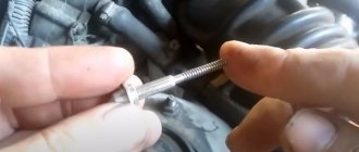
- two pieces of wire of different colors with a diameter that allows you to pull them through the slot in the generator cover (in our case, red and black);
- plastic retainer for holding wires in the regulator body.
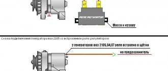
The diode connection diagram looks like this:
In this case, when switch S1 is set to position “1”, the generator is operated in normal mode - the diodes are excluded from operation.
Setting the S1 toggle switch to position “3” ensures the connection of one diode, as a result of which the output voltage of the generator increases by 0.3-0.4V.
Moving the switch to position “2” activates two Schottky diodes (connected in series), and accordingly the voltage will increase by 0.6-0.8V.
The approximate location of the circuit parts in the case is shown in the photo below (we connect the red wire to the “input” and the black wire to the “output”).
To ensure the connection of our homemade diode device to the generator, we supply the red wire with a male terminal (we will connect it to the female wire coming from the diode bridge). In turn, we supplement the black wire with a “female” type contact and connect it to the excitation terminal of the voltage regulator. As mentioned above, we pull the wires through the gap in the plastic cover of the generator.
At the last stage of installation, we fix the device body in any convenient place (away from strong heat sources).
Installing a factory-made three-level voltage regulator
For those car enthusiasts who are not too confident in their abilities and are not financially constrained, there is an easier and faster way to deal with voltage sags, namely installing a three-level voltage regulator purchased in a store. To perform such work, you do not need special technical skills, but you just need to purchase a regulator and prepare a minimum set of tools in the form of a “10” key, a Phillips screwdriver, a knife and a device for crimping contacts.
Installation of a three-level voltage regulator is performed in the following sequence:
- To avoid problems, disconnect the corresponding power wire from the negative terminal of the battery;
- Using a “10” wrench, unscrew the M6 nut on the generator and move the wires aside;
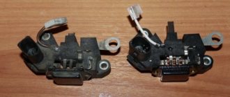
- We disconnect the block with wires from the generator and, pressing the latches, remove the protective casing from it;
- Unscrew the screws securing the voltage regulator and disconnect it;
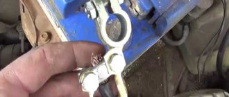
- In place of the old regulator, we install the brush holder of the new device (the outgoing wire, for reliability, can be additionally reinforced with sealant);
- We stretch the harness going from the brush holder to the body of the three-position regulator along the standard wiring, fixing it with plastic clamps;
- We fix the regulator body in any convenient place, not forgetting to ensure the presence of a reliable “ground” (even to the point of extending an additional shunt wire connecting the regulator to the generator body).
At the final stage, we connect the negative battery, start the engine and check the operation of the power supply system with a change in load from minimum to maximum.
Tags VAZ, generator, Voltage regulator
What to do if the voltage relay fails?
If you are new to electronics, then such an undertaking will be quite difficult.
As we mentioned earlier, the main element of the circuit is a certain number of diodes. Finding three-stage switches for them is quite problematic. In addition, you need to correctly calculate and install radiators for cooling. Otherwise, the risk of diode burnout increases significantly.
During the development of the regulator, long wires will be needed, because the connection is made directly to the device through the cover.
Additionally, you will need to make or find a suitable plastic case for such equipment. All internals must be securely fastened inside the device.
It happens that the relay fails at the most inopportune moment, when you still have a drive home and the battery is not charging. The battery capacity in economical mode can ensure fairly long engine operation, which will allow you to get to the repair site without any problems. Below we will provide a list of recommendations that will help you drive, as they call it, “on battery power” and not stall.
- If the battery is overcharged, the relay must be disconnected from the circuit. To do this, the contact wires are removed from it and left hanging. In the case of the “ten”, it is enough to unplug the plug with the wire from the generator brush connector. Thus, battery charging is turned off, and further movement will no longer harm the battery.
- Many experts suggest going the other way - turning off the generator excitation winding. To do this, remove the corresponding fuse. However, this can be done if you know where the fuse is located.
- If the battery is weakly charged, then there is practically no reason to panic. To get to your destination, you need to maintain high speeds in order to, at least a little, bring the voltage value to the nominal value. Before stopping the engine, it is recommended to maintain the speed at 3000 rpm for a few seconds using the gas pedal. This will prepare the battery for the next start.
- Avoid using music, power windows, headlights (especially high beams), and other electrical devices unless their use is absolutely necessary. This will save battery power well.
Relay regulator VAZ
- disconnect the negative terminal from the battery;
- disconnect the drive block from the terminal marked “D”;
- unscrew the nut, which is located under the rubber boot (it needs to be moved a little to the side);
- disconnect all existing wires in the contact pin;
- unscrew the nut in the generating device circuit (this fastener secures the terminal) and remove it.
Then you will need to remove the generator casing by unscrewing the nuts (there are three of them) that hold it in place, as well as dismantle the relay housing and remove the screw securing the disassembled mechanism from the rectifier compartment. Now the VAZ 2110 voltage regulator can be easily removed. You can install a new device instead. After replacing the relay, all the described steps are performed in the reverse order.
- If the battery is overcharged, the relay must be disconnected from the circuit. To do this, the contact wires are removed from it and left hanging. In the case of the “ten”, it is enough to unplug the plug with the wire from the generator brush connector. Thus, battery charging is turned off, and further movement will no longer harm the battery.
- Many experts suggest going the other way - turning off the generator excitation winding. To do this, remove the corresponding fuse. However, this can be done if you know where the fuse is located.
- If the battery is weakly charged, then there is practically no reason to panic. To get to your destination, you need to maintain high speeds in order to, at least a little, bring the voltage value to the nominal value. Before stopping the engine, it is recommended to maintain the speed at 3000 rpm for a few seconds using the gas pedal. This will prepare the battery for the next start.
- Avoid using music, power windows, headlights (especially high beams), and other electrical devices unless their use is absolutely necessary. This will save battery power well.
Recommendations for increasing the service life of the regulator
Generator voltage regulator relay: design and principle of operation
In order to increase the service life of the voltage regulator, you must adhere to several simple rules aimed at implementing preventive measures. Among them:
- do not allow excessive contamination of the generator, periodically inspect its condition, and, if necessary, dismantle and clean the unit;
- check the tension of the alternator belt, tighten it if necessary (either yourself or in a car service);
- monitor the condition of the generator windings, in particular, do not allow them to darken;
- check the contact on the control wire of the relay-regulator, both its quality and the presence of oxidation on it;
- Perform periodic voltage checks on the vehicle battery with the engine running.
Following these simple rules will allow you to increase the resource and service life of both the generator and the vehicle voltage regulator.
Results
Checking the voltage regulator relay is not a difficult task, and almost any car enthusiast with basic repair skills can handle it. The main thing is to have the appropriate tools for this - a multimeter, a power supply with a voltage regulator (although you can connect it to a battery with a charger), a 12 V lamp and pieces of wires for mounting the appropriate circuit.
If during the inspection you find out that the regulator is out of order, then it must be replaced (repair work is usually not carried out). The main thing is not to make a mistake when choosing it and purchase the part that is suitable specifically for your car.
Relay regulator VAZ
Replacing the VAZ 2110 generator relay can be done in two ways: with removing the generator and without removing it. Both options can be done at home, although the second involves fewer manipulations with the car. But despite this, the first option may be simpler for some. Anyone can replace the VAZ 2110 generator regulator relay if they read and study the instructions below.
Question/answer on fuses for VAZ 2110, 2111, 2112
Installing a three-level voltage regulator on Lada
We answer some questions sent on the topic.
Tell me, the left turn signal and high beam headlights on the VAZ 2110 stopped working, what could be the reason? Open the fuse and relay box, the contact may have come loose, move the wires, look and check, and if necessary, replace the fuses yourself.
Please tell me I'm already tired of it, the washer motor shorts, the light in the cabin with the clock and fuse F17 blows? Install a light bulb instead of a fuse, turn off all devices that are connected to this fuse. Turn on the ignition. If the lamp does not light, connect everything back one by one. Whichever one lights up, that's where the problem lies. If it lights up immediately, there is a short in the wiring.
Tell me what could be wrong, the reverse lights are dimly lit, if you remove one bulb, the second one starts to burn normally, put them back in place, both light up at half power. The brake lights on the same board light up normally. This problem is due to poor ground contact.
Why does fuse F8 melt? Look under the cover on the driver's side. If the catalyst was clogged, then the wires that go to heating were broken.
Why is the stove turned off, but hot air comes in? If the air is hot, but the switch is set to cold, then the electric drive of the faucet has soured.
The car starts only periodically when I turn on the ignition and the lights come on. I put the starter on direct and it starts. Tell me what is the problem? Place a relay between the lock and the starter, it won't help - it's the ignition switch.
What does the second set of fuse boxes do?
The symbols F1-F20 indicated below in the electrical diagram are the elements that characterize the set of fuses. The electrical circuit in a VAZ-2110 car is protected using fuses based on the specific calculation of the model for the rated current value specified upon purchase.
At the same time, fuses are not responsible for the quality operation of the circuit consisting of a sample battery, a separate type of generator circuit, the ignition system and engine valve starting. To replace a faulty fuse in this mounting block, follow the following plan:
- Find a fuse that has mechanical damage or its body has burned out;
- According to the instructions, determine and eliminate the reason why it turned out to be faulty;
- Install a new fuse using the backup model.
Tip: Never try to replace a fuse with special jumpers. In the future, this will lead to failure of those devices that are assigned to this fuse.
Diagram with designations for the second set of fuses in the block
All fuses are divided according to their interaction with electrical equipment as follows:
- F1 (current 5A) - fuse responsible for the set of lamps that illuminate the license plate, the entire instrument panel, including the side lights and lighting in the trunk.
- F2 (current 7.5A) - element that regulates the low beam on the left headlight.
- F3, F4 (current 10A) - responsible for the operation of high beam in the left headlight and right fog lamp, respectively.
- F5 (with a current of 30A) - is responsible for the electric window motor at the front and rear car doors.
- F6 (with a current of 15A) - refers to the operation of a portable lamp.
- F7 (with a current of 20A) - regulates the operation of the fan motor in the cooling system of a 16-valve engine, as well as the operation of the sound signal.
- F8 (with a current of 20A) - supplies current to the heating elements located on the rear window. In addition, together with the contacts from the relay, it transmits current to the windshield.
- F9 (with a current of 20A) - is responsible for the operation of the recirculation valve. It also interacts with the windshield wiper and washer sensors and headlights.
- F10 (with a current of 20A) - is a backup fuse.
- F11 (with a current of 5A) - regulates the operation of lamps with side lights on the starboard side.
- F12 and F13 (with a current of 10A) - both fuses regulate the operation of the right headlight, responsible for the low/high beam, respectively.
- F14 (current 10A) - adjusts the light from the left fog lamp.
- F15 (with a current of 20A) - interacts with the electric heating of the driver and passenger seats. Protects the car from unauthorized blocking of the central locking in the trunk.
- F16 (with a current of 10A) - transmits current to the breaker relay to ensure the operation of the direction indicator of the left and right headlights, and is also used to give an emergency signal (when using the emergency signal mode on the VAZ-2110).
- F17 (current 7.5A) - works with the car interior lighting lamp, brake light lighting, individual lighting of the ignition system switches and regulates the operation of the trip computer.
- F18 (with a current of 25A) - illuminates the glove compartment, supplies current to the heating system controllers and the cigarette lighter on the dashboard.
- F19 (with a current of 10A) - is responsible for the operation of the door locks, and also informs the driver about the presence of a malfunction in the brake light lamps or side light elements.
- F20 (current 7.5A) - works with the lamps of the rear pair of fog lights of the VAZ-2110.
Having dealt with the fuses, you can also learn about how to bleed the brakes on a VAZ-2110. Often the operation of the braking system greatly affects the operation of the car in general and electrical equipment in particular.
Voltage regulator - its main functions
Replacing the VAZ 2110 generator manifold
On a VAZ 2110 car, the voltage potential in the generator is formed under the influence of alternating current. This phenomenon becomes possible due to the presence of silicon diodes in the generating device of the vehicle. The generator rotor (the rotating component of the mechanism) operates according to the following diagram:
- First, the crankshaft begins to function, which is affected by the current;
- the crankshaft sets the movement of the rotor;
- After this, the generating device itself begins to work.
All stages of the sounded process are monitored by a voltage regulator, which is also often called a relay. It is this that is considered the main control unit of the generator.
Without a regulator, the current-generating mechanism of the VAZ 2110 will not perform its tasks, which are listed below:
- starting the generator;
- control (in offline mode) of current supply;
- “holding” in a certain voltage range.
The described relay cannot be repaired. In the event of a breakdown, the regulator must be replaced, which is done after checking the functionality of this unit.
Regulator relay - purpose, operating principle, types.
The reason for the appearance of a relay regulator in a car's electrical circuit was the fact that the generator does not always supply the battery with the voltage necessary for proper charging. The main problem is the variable speed of the crankshaft and, accordingly, the shaft of the electric generator, the latter generating an unstable voltage. The functioning of on-board network devices and battery charging require stabilization of the generator output signal.
The regulator relay performs the following functions:
- Voltage stabilization at the generator output in a given range;
- Cut-off (disconnection of charge circuits) when the maximum permissible level is exceeded.
The excitation winding of the generator is connected through the device. In fact, the PP performs the functions of a negative feedback circuit - an increase in the speed leads to an increase in the voltage at the output of the generator (battery terminals), thanks to the PP, it decreases on the excitation winding, a decrease in the excitation magnetic flux, and a decrease in the output voltage of the electric generator. When the speed decreases, the reverse process occurs. In this way, the battery receives up to 14.2-14.5 V (in some car models up to 14.8 V) regardless of the shaft rotation speed.
If the specified value is exceeded at the battery contacts, the supply of voltage to the terminals is completely blocked.
Types of relay regulator.
RRs are classified according to several criteria.
Based on the element base used, devices are divided into:
- Relay, using only switching relay contacts for stabilization and cutoff;
- Transistor and hybrid transistor-relay, built on the basis of semiconductor elements (used in cars produced before the 90s);
- Integrated, the architecture of which is based on integrated semiconductor and solid-state switching components, operating in modern cars;
- Microprocessor (microcontroller) with software specification of operating algorithms (modes) (widely used in high-end cars, for example Audi, BMW).
External (separate devices mounted on body structures);
- Built-in, structurally included in the generator;
- Combined with the brush assembly of the electric generator.
There are also devices with adjustment by “+” and “-” (connected to the break of the corresponding wire), two-, three- and multi-level.
We install the voltage regulator of the VAZ 2110 generator
The voltage regulator on a modern car automatically and continuously adjusts the excitation current of the generator. Moreover, this process proceeds in such a way that when the current load and rotation speed of the generator changes, the value of its voltage remains in a strictly defined range.
Voltage regulator - its main functions
On a VAZ 2110 car, the voltage potential in the generator is formed under the influence of alternating current. This phenomenon becomes possible due to the presence of silicon diodes in the generating device of the vehicle. The generator rotor (the rotating component of the mechanism) operates according to the following diagram:
- First, the crankshaft begins to function, which is affected by the current;
- the crankshaft sets the movement of the rotor;
- After this, the generating device itself begins to work.
All stages of the sounded process are monitored by a voltage regulator, which is also often called a relay. It is this that is considered the main control unit of the generator.
Without a regulator, the current-generating mechanism of the VAZ 2110 will not perform its tasks, which are listed below:
- starting the generator;
- control (in offline mode) of current supply;
- “holding” in a certain voltage range.
The described relay cannot be repaired. In the event of a breakdown, the regulator must be replaced, which is done after checking the functionality of this unit.
How to properly check the VAZ-2110 generator
One of the most basic spare parts of any car is, of course, an electric generator. As soon as this device fails to function properly, the car lasts no more than 2 hours
That is why it is important not only to repair the generator correctly, but also to diagnose it in time. This article will tell you how to properly check the VAZ-2110 generator.
The following characteristics of the vehicle state indicate that the generator has failed:
- when the engine is running, the battery lamp shows a complete lack of charge;
- during operation, the part constantly overheats;
- the electrolyte inside the battery constantly boils away;
- the headlights begin to dim, the horn makes a quiet (muffled) sound;
- when idling, pressing the gas pedal, the brightness of the headlights increases, and the generator begins to make super-strong revolutions;
- the presence of extraneous sounds (howling, humming, creaking, crackling, and so on);
- the same voltage readings when the car engine is running and when it is turned off.
The VAZ-2110 generator consists of:
- rotor;
- front roof;
- bearing;
- stator;
- slip rings;
- regulator;
- diode bridge;
- back cover.
How to replace the diode bridge of a VAZ-2110 generator
The operation of this type of generator is based on electromagnetic induction by passing a magnetic flux through a copper coil. This is only permissible if electrical voltage passes through the coil.
The voltage source on the VAZ-2110 is the rotor. While moving, it rotates continuously. The rotor consists of a shaft, a pole structure and slip rings.
How to check a VAZ-2110 generator with your own hands
It is very easy to check the operating status of the generator, and you can do it yourself without leaving your home. To check the quality of a part, it is necessary to disassemble it into small parts. In addition, if a segment breaks down, it will be easier to replace it with a single one than to buy a new generator. So, let's look at all the spare parts that need to be disassembled and checked on the generator:
- Pulley. This part should not have any damage or wear on the teeth, otherwise it will jam and the generator will not be able to fully operate. Replacing it is not at all expensive, so if there are any malfunctions, it is better to replace it immediately.
- Bearing. The most important one is the rear bearing. To check its functionality, make several rotational movements, changing the direction of rotation. If scrolling is difficult or unnecessary sounds occur (friction, creaking, etc.), then this spare part must be replaced with a new one.
- Winding. To check this part you will need a multimeter or ohmmeter. Connect the rotor slip rings to the probes of the selected device. During normal operation, the resistance on the device should range from 4.5 to 10.0 ohms. If the resistance has a different value, then the entire rotor must be replaced, along with the armature.
- Transfer the probes of the device to the rotor housing. In good condition, the ohmmeter will show an infinity value, but in a broken state the value will be close to zero.
- With the same device you need to check the quality of the stator winding.
- To check the diode bridge, it is necessary to connect the “plus” probe to the common bus of the rectifier unit, and apply the “minus” probe to the opposite terminals of each diode. Perform the procedure one by one. When changing probes, the resistance readings on the device should differ by several hundred times. Otherwise, it is necessary to replace the entire rectifier unit.
- Carefully inspect the regulator brushes. Most often, they are the reason, so this part needs systematic and regular replacement. Each protruding part must have a length of at least 0.5 cm.
In addition, their movement should be smooth and not interfere with the operation of the preload springs. To check the operation of the regulator itself, you will need a car test lamp. Connect it to the carbon brushes of the regulator, and connect the voltage source to the terminals.
Remember to observe polarity. First, apply a voltage of 13 volts, the lamp should light up. Then gradually increase it. When the voltage reaches 15 volts, the lamp will turn off.
Reasons for replacement
Relay replacement is needed in the following cases:
- The brushes are worn out. By the way, this is the main reason. The fact is that due to their wear, contact with the relay is lost, so due to lack of power, the generator will stop working.
- A breakdown is observed in the circuit, which leads to an increase in voltage in the system.
- Wire breaks causing loose contacts.
- Damage to the housing or fastenings. This is not something to joke about, as it can lead to an unwanted short circuit.
Relay replacement
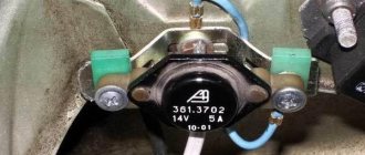
To remove the relay, it is not necessary to dismantle the generator. To do this you need:
- Find the relay.
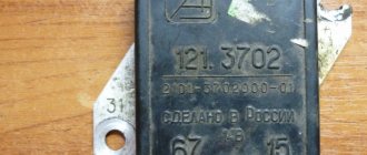
Note: It is usually black and is attached to the generator with a yellow wire.
- Disconnect the negative terminal of the battery.
- Unscrew the two bolts securing the generator.
- Remove the yellow wire going to the relay from the generator.
- Remove the relay. Examine it carefully. If the brushes are worn out, replacement cannot be avoided.
- If any of the wires are broken or there are holes on its surface, then you can only get by by replacing them.
Note: you can simply insulate them without even replacing them with new ones. Although the relay is inexpensive - only 70 rubles.
- Check the new voltage regulator, and then attach it to the generator.
- Reconnect the yellow wire and battery terminal.
Add a commentInstructions for mounting the generator on a VAZ 2112 with your own handsReplacing the diode bridge of the VAZ 2110 generator on your ownReplacing the relay in the VAZ 2109 generator - couldn’t be easierVAZ 2112: generator faults and their identification
The amount of electrical voltage generated by a car generator is not constant and depends on the number of revolutions of the crankshaft. In order to stabilize it, a special regulator is designed. We will talk about it in this article using the example of a VAZ-2110 car.
checking and repairing voltage regulator VAZ 2110 | VAZ 2111 | VAZ 2112
The operation of the voltage regulator is to continuously and automatically change the generator excitation current so that the generator voltage is maintained within specified limits when the generator speed and load current changes. Checking the voltage regulator on cars of the VAZ 2110 family
To check, you must have a DC voltmeter with a scale of up to 15-30 V, accuracy class no worse than 1.0.
After 15 minutes of engine operation at medium speed with the headlights on, measure the voltage between the “B+” terminal and the “ground” of the generator. The voltage should be within the range of 13.2-14.7 V. If there is a systematic undercharging or overcharging of the battery and the regulated voltage does not fall within the specified limits, the voltage regulator must be replaced. Checking the removed regulator of a VAZ 2110, VAZ 2111, VAZ 2112.
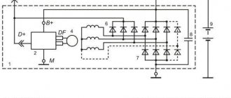
The regulator assembled with a brush holder, removed from the generator, is checked according to the diagram shown in Fig.
7-12. Between the brushes, turn on a 1-3 W, 12 V lamp. Connect a power source to the “D+” and “ground” terminals of the regulator, first with a voltage of 12 V, and then with a voltage of 15-16 V. If the voltage regulator is working properly, then in the first case the lamp should be on , and in the second - go out. If the lamp lights up in both cases, then there is a breakdown in the regulator, and if it doesn’t light up in both cases, then either there is a break in the voltage regulator, or there is no contact between the brushes and the terminals of the voltage regulator. The latter can be checked by connecting the wires from the lamp not to the brushes, but directly to the “D+” and “DF” terminals of the voltage regulator. Checking the capacitor
The capacitor is used to protect the electronic equipment of VAZ 2110, VAZ 2111, VAZ 2112 cars from voltage pulses in the ignition system, as well as to reduce interference with radio reception. Damage to the capacitor or loosening of its mounting on the generator (deterioration of contact with ground) is detected by an increase in interference to radio reception when the engine is running. Approximately the serviceability of the capacitor can be checked with a megger or tester (on a scale of 1-10 MOhm). If there is no break in the capacitor, then at the moment the probes of the device are connected to the terminals of the capacitor, the arrow should deviate in the direction of decreasing resistance, and then gradually return back. The capacitance of the capacitor, measured with a special device, should be 2.2 μF ± 20%. rice. 7-12. Circuit for checking the voltage regulator: 1 - test lamp; 2 — output (ground) of the voltage regulator; 3 — terminal “DF” of the voltage regulator; 4 - voltage regulator; 5 — terminal “D+” of the voltage regulator; A - to the power source
When using site materials, an active link to car-exotic.com is required!
The generator voltage regulator (RN) cannot be repaired; it can only be replaced with a new one. However, before replacing it, you should make sure that it is the one that has failed. We are studying the question “how to check the voltage regulator of a VAZ 2110.”
Checking the voltage regulator on a car
To check the pH, you will need a DC voltmeter with a scale of up to 15.30 volts. We check it this way: with the engine running at medium speed and the headlights on, we measure the voltage at the battery terminals. It should be within 13.5. 14.2 V.
If the regulated voltage does not fall within the specified limits, and there is a systematic undercharging or overcharging of the battery, then it is possible that the voltage regulator is faulty and needs to be replaced.
Checking the voltage regulator after dismantling it
The removed generator voltage regulator is checked according to the following diagrams: (the first diagram for the old-style LV): It is better to check the relay-regulator assembled with the brush holder, since in this case you can immediately detect breaks in the brush leads and poor contact between the terminals of the voltage regulator and the brush holder. You need to turn it on. lamp 1. 3 W, 12V between brushes. To terminals “B”, “C” and to the regulator ground, connect a power source first with a voltage of 12.14V, and then with a voltage of 16.22V. (a 12V power source can be a battery, and a 16. 18V power source can be the same battery, but with 2..4 of the cheapest AA batteries connected to it in series.)
If the voltage regulator is working properly, then
- in the first case, the lamp should be on,
- in the second - go out.
If the lamp lights up in both cases, then there is a breakdown in the regulator, and if it doesn’t light up in both cases, then there is a break in the regulator or there is no contact between the brushes and the terminals of the voltage regulator.
An example of a practical test of the voltage regulator 54.3702 using a 21W lamp: By the way, a three-level voltage regulator can also be installed on the “ten”.
Device check
The relay-regulator of the voltage of the VAZ 2106 generator, “kopecks”, and foreign cars is checked equally. As soon as you remove it, look at the brushes - they should be more than 5 millimeters long. If this parameter is different, the device must be replaced. To carry out diagnostics, you will need a constant voltage source. It would be desirable to be able to change the output characteristic. You can use a battery and a couple of AA batteries as a power source. You also need a lamp, it must run on 12 Volts. You can use a voltmeter instead. Connect the plus from the power supply to the voltage regulator connector.
Accordingly, connect the negative contact to the common plate of the device. Connect a light bulb or voltmeter to the brushes. In this state, voltage should be present between the brushes if 12-13 Volts are supplied to the input. But if you supply more than 15 Volts to the input, there should be no voltage between the brushes. This is a sign that the device is working properly. And it doesn’t matter at all whether the voltage regulator relay of the VAZ 2107 generator or another car is diagnosed. If the control lamp lights up at any voltage value or does not light up at all, it means that there is a malfunction of the unit.
Three-level generator voltage regulator for the “ten”
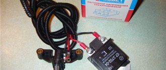
When the heating system, headlights and other additional loads are turned on on the VAZ 2110, the car battery discharges very quickly. This phenomenon is observed even when the “native” generator relay is functioning normally. A three-level regulator allows you to get rid of this problem. You can purchase it at any auto store, equip yourself with a simple set of tools (terminal pliers, a knife, an S10 open-end wrench and a Phillips screwdriver) and install it on the car yourself.
The three-level mechanism is mounted as follows:
- first remove the old relay according to the algorithm given above;
- grind the ends of the spacer bushing using a file (this operation ensures more reliable contact with the diode bridge);
- a new element with a brush holder (sold as a set) is installed in place of the relay;
- Sealant is used to seal the cable entry point;
- put back the plastic casing;
- lay the cable along the standard wiring to the area where the relay is mounted, and secure the new wire tightly with small plastic clamps.
It is recommended to connect the housing of the installed voltage relay and the autogenerator using a reliable shunt. This ensures the necessary contact of the device with ground. However, you can do without a shunt.
The mounted three-level mechanism should be checked with a tester at full consumer load (window heating, stove, headlights, etc. are turned on). At maximum, the device should show 14.5 V, in normal mode - 14.1 V, at minimum - about 13.4 V.
Didn't find the information you are looking for? on our forum.
We recommend reading:
Replacing the cabin filter on a VAZ 2110, step-by-step instructions
How to change the wing on a VAZ 2107
The ball joint of the VAZ 2110 cannot be removed
Replacing the timing belt on a VAZ 2109 carburetor, reasons for belt breakage
Ignition switch pinout for VAZ 2109 injector. 2101-2107-2109-2110
VAZ carburetor does not start well when hot, causes and solutions
VAZ 2111 8 valves injector
How to change high-voltage wires on a VAZ 2107 injector
Which TRN is suitable for LADA
| Generator, article number | Automobile | TRG, article number |
| 26.3701, 37.3701, 371.3701, 372.3701 | VAZ-2107, -2108, -2109, -2110, OKA | 67.3702-01 |
| 3002.3771, 332.3771, 3202.3771, 3212.3771, 4302.3771, 94.3701, 9402.3701, 9422.3701, 3740.3771-38, 3743.3771-61, 3747.3771- 93, eld-a-21214, LG01214 | VAZ, GAZ | 67.3702-02 |
| 4052.3701, 409.3701, PRAMO “ISKRA” 5102.3771, -10, 5112.3771, -10, 5122.3771, -10, -30, 5142.3771, AAK 5727 | VAZ, GAZ, UAZ with generators PRAMO “ISKRA” 5102.3771, 5122.3771 | 67.3702-04 |
| G222 | VAZ-2104, -2105, -2107 | 67.3702-09 |
| 26.3701, 37.3701, 371.3701, 372.3701 | VAZ-2107, -2108, -2109, -2110, OKA | 67.3702-11 |
| 3002.3771, 332.3771, 3202.3771, 3212.3771, 4302.3771, 94.3701, 9402.3701, 9422.3701, 3740.3771-38, 3743.3771-61, 3747.3771- 93, eld-a-21214, LG01214 | VAZ, GAZ | 67.3702-12 |
| generators with an additional three diodes, the excitation winding of which is connected to the positive circuit | 673.3702 |
Where can I buy
: in our online store (Relays category).
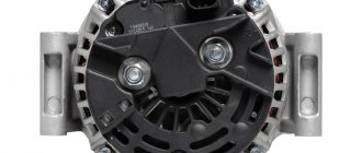
Generator VAZ 2110
Purpose
The generator set is a fairly reliable device that can withstand both increased vibration of the power unit and large differences in engine compartment temperatures, and also has high resistance to the effects of a damp environment and dirt. The generator output current parameters must be stable in all engine operating modes, at any its loads and rotational speeds. The main requirements facing the generator are:
- The parameters of the generated electric current must be such that, under any engine operating modes and load on the vehicle’s on-board network, not only does the battery not intensively discharge, but it is also recharged;
- At any engine speed and load changes throughout the entire range of its operation, the voltage in the vehicle's electrical circuit must be stable and correspond to the declared value.
Device
Before you look for alternator faults in your VAZ 2110, you need to know that the fundamental design and principle of its operation are the same for all types of cars. They can differ only in dimensions, workmanship and location of mounting fasteners. Therefore, to broaden your horizons, you can listen to the advice of owners of all brands of cars, since some generator spare parts are interchangeable.
Replacement in the VAZ 2110 generator
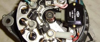
The photo highlights the main components of the generator:
- Alternator belt pulley (I hope there is no need to explain its purpose);
- A housing consisting of a front half located on the pulley side and a rear half, which is installed on the slip ring side. In addition, in the rear part of the case there is a brush assembly, a rectifier, a voltage regulator, as well as electrical wiring leads for connecting to the vehicle's electrical circuit.
The stator is installed in the housing, and the rotor support bearings are placed; it also has fastenings for installing the generator on the car engine.
- A rotor with excitation windings, the terminals of which are connected to cylindrical slip rings made of copper;
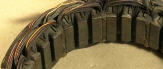
- The heart of the generator is the stator. It is in the grooves between its steel sheets where the three-phase winding is located and the electric current necessary for the car is generated;
- Assembly of rectifier diodes (no comments);
- A voltage regulator is necessary to maintain the voltage in the vehicle's electrical circuit within the specified parameters during changes in loads, generator speed and ambient temperature;
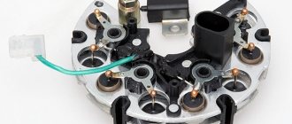
- Brush assembly, where there are spring-loaded brushes in contact with the rotor slip rings;
- Plastic cover protecting the diode module.
Principle of operation
Let's move on to the most interesting part of our article. So, turn the ignition key in the lock and:
- Electric current is supplied to the slip rings, through the brush assembly, and then to the rotor field winding;
- In the winding of the rotor, which begins to rotate simultaneously with the engine crankshaft, there is a magnetic field that penetrates the stator windings, resulting in a variable voltage at its terminals;
- When the generator reaches a certain rotation speed, it goes into self-excitation mode, that is, the current to the rotor field winding begins to flow directly from the generator itself;
- The generated alternating voltage is converted into direct voltage using a rectifier unit. It is in this state that the processes of charging the battery and providing electricity to current consumers take place;
- The voltage regulator comes into operation while the vehicle is moving, when the load on the generator and its rotation speed change. Its task is to regulate the switching time of the exciting rotor winding.
This time decreases with lower external loads and with increasing generator rotor speeds, and increases with increasing loads and decreasing rotation speeds.
Working principle of AC generator set
I hope my brevity did not prevent you from understanding the principle of operation of an alternating current generator set, otherwise you can always find a video on the topic on the Internet.
So, the main parameters are:
- Rated values of voltage, current and excitation frequency;
- The frequency with which self-excitation of the winding occurs;
- Efficiency factor (efficiency).
In our case, the electrical system has a rated voltage of 12 volts, and the rated current is the maximum amount obtained at the rated speed of the generator (80 amperes at 6000 rpm).
Theory of the issue
Three-level voltage regulator for VAZ 2114
While the car is moving, a dead battery receives a charge voltage of 13.6 to 14.2 V. For the correct and stable operation of all systems in the car, these voltages must be maintained until the engine starts and the crankshaft rotates. Together with the motor, torque is supplied to the generator through the drive belt. At this moment, an amount of energy is generated that will be sufficient for the stable functioning of all systems and to maintain a charge on the battery.
If the generator does not charge, then in most cases the reasons must be sought in the excitation circuits, as well as in the output voltage circuits from the generator to the battery. But this is not always the case. Sometimes problems are related to the generator itself.
When the driver turns the key in the lock, the relay in the ignition system also starts at the same time. “Plus” flows through the relay and fuse in the mounting block. Next, the voltage passes through the on-board network, reaching the battery charge lamp and charge sensors. It then passes through diodes, relays, elements in the mounting block and finally to the connector in the generator. There, electricity comes to the relay-regulator and, passing through brushes and slip rings, enters the exciting winding.
conclusions
In the electrical system of a car, the voltage regulator relay of the Bosch generator (as, indeed, of any other company) plays a very important role. Monitor its condition as often as possible and check for damage and defects. Cases of failure of such a device are not uncommon. In this case, in the best case, the battery will be discharged. And in the worst case, the supply voltage in the on-board network may increase. This will lead to the failure of most electricity consumers. In addition, the generator itself may fail. And its repair will cost a tidy sum, and considering that the battery will fail very quickly, the costs will be astronomical. It is also worth noting that the Bosch generator voltage regulator relay is one of the leaders in sales. It has high reliability and durability, and its characteristics are as stable as possible.
Signs of LV malfunction
In VAZ-2110 cars, the voltage regulator breaks quite rarely, but if this happens, signs of its malfunction may be:
- Failure of the control panel backlight.
- Exceeding the battery charging voltage.
- Insufficient battery charge voltage.
If the voltage regulator relay of the VAZ-2110 breaks down, the fuses responsible for the safety of the power supply circuit of the instrument panel may blow out. If the backlight lamps do not light up when the ignition is turned on, there is a possibility that the LV is to blame.
The same can be assumed when the voltmeter needle, indicating the battery charge level, deviates from its usual position, i.e., shows higher or lower voltage.
It is this symptom that most often manifests itself when the voltage relay regulator of the VAZ-2110 generator fails. And if in the second case it can only cause the battery to discharge, then in the first it threatens to boil the electrolyte and destroy the battery plates.