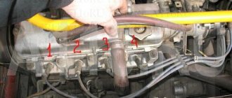
Sometimes, when repairing their car, drivers have to dismantle high-voltage wires (otherwise known as armored wires). At the same time, not all motorists realize to remember or write down the correct order of connecting these wires, as a result of which the repaired car may simply not start. We will talk about the order of the cylinders of the VAZ 2114 and in what sequence the armored wires should be connected to them in today’s article.
Ignition in a VAZ 2114
Firing order
The cylinders in a car do not work chaotically, because for stable operation of the engine and alternate execution of all four strokes, their strict synchronization is required.
So there is a special order of operation of the cylinders of the VAZ 2114, thanks to which each of them at one point in time performs any of 4 strokes, namely:
- Injection of a mixture of fuel and air that fills the entire volume of the cylinder.
- Compression of the working mixture due to the upward movement of the piston.
- The combustion of the working mixture and the expansion of the resulting gases pushes the piston in the opposite direction, thereby driving the connecting rod and crankshaft.
- The release of exhaust gases from the cylinder with their further discharge into the exhaust system.
It is worth noting that on cars of different brands and even models, the engine may have a different operating diagram, but the order of operation of the VAZ 2114 injector cylinders always looks like this: 1-3-4-2. According to this diagram, the high-voltage wires should be connected.
For greater convenience, the cylinders are numbered accordingly, starting from the front cover of the engine.
conclusions
The design of the VAZ-2114 eight-valve injection engine is in many ways similar to the first generation of this engine, the Samara. Of course, the designers made many changes to the characteristics of the power unit, but in many ways they remained similar. Repair and maintenance of this engine must be carried out regularly, which will not only extend its life, but also reduce wear on the parts inside.
The car is equipped with a gasoline engine, four-stroke, four-cylinder, in-line, eight-valve, overhead camshaft and liquid cooled model 2111 or 11183.
Engine section 11183 (1.6i):
1 – oil pan drain plug; 2 – oil pan; 3 – crankshaft; 4 – oil filter; 5 – coolant pump; 6 – exhaust manifold; 7 – piston; 8 – rod for attaching the intake manifold; 9 – installation of the intake manifold and exhaust manifold; 10 – inlet pipe; 11 – nozzle; 12 – fuel rail; 13 – receiver; 14 – bracket; 15 – head cover; 16 – camshaft bearing housing; 17 – camshaft; 18 – pipe for the crankcase ventilation system; 19 – valve pusher; 20 – head; 21 – bolt securing the head to the cylinder block; 22 – valve; 23 – candle; 24 – cylinder head gasket; 25 – upper compression ring; 26 – lower compression ring; 27 – oil scraper ring; 28 – piston pin; 29 – fitting for installing the oil dipstick; 30 – connecting rod; 31 – flywheel; 32 – cylinder block; 33 – oil pan gasket; 34 – oil dipstick; 35 – oil sump
The cylinder block is made of cast iron, the cylinders are turned inward. The internal cavities of the block for the coolant are formed when it is filled, and the oil supply channels are formed by drilling. At the bottom of the block, the five crankshaft main bearings are machined. The main bearing caps are machined together with the bearings and are therefore not interchangeable. To prevent the covers from being mixed up during installation, they are marked with the serial number of the bearing, starting with the crankshaft pulley. The second main bearing cap has two threaded holes for the oil intake bolts. Steel-aluminum bushings are installed in the supports and main bearing caps. On both sides of the third main bearing support there are bushings for installing thrust half-rings that prevent axial movement of the crankshaft. The front half-ring is steel-aluminum (yellow on one side, steel on the other), the rear half-ring is metal-ceramic (yellow on both sides).
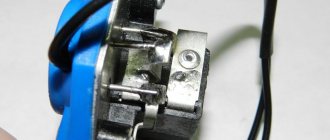
Armored wires and their connections
Having found out how the location of the VAZ 2114 cylinders affects their connection, it is worth talking about the high-voltage wires with which this is done.
These wires themselves are quite different from ordinary electrical wires - they have an increased layer of insulation, protective shielding, as well as metal connecting tips and protective caps made of heat-resistant plastic. The main purpose of these wires is to transmit a high-voltage pulse from the ignition unit to the cylinders (it is this pulse that allows the spark plugs to ignite the working mixture).
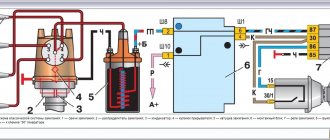
The connection of armored wires should be made taking into account the ignition order of the VAZ 2114 injector and the numbering of the cylinders (this was mentioned above). For greater convenience, you should be guided by the numbering present on the ignition module - just connect socket number 1 to the corresponding cylinder, socket number 2 to cylinder number 2, etc. It is extremely difficult to make any mistake here.
Legend
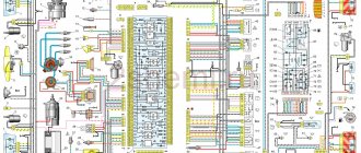
For ease of maintenance and installation, the electrical wires in the diagrams are made in different colors, identically laid in the car, so that their purpose can be visually determined.
For brevity, colors are indicated by the first letters of the name:
- Blue – “G”;
- Brown – “K”;
- Gray – “C”;
- White – “B”;
- Orange – “O”;
- Yellow – “F”;
- Black – “H”;
- Green – “Z”;
- Pink - "R".
Thanks to the colors, it is easy to determine whether the rein belongs to a particular chain
For reference: the red wire is traditionally used to supply power from the positive terminal of the generator or battery. Therefore, in all diagrams contained in the factory instructions, it is designated by the letter “P”.
The article Wiring diagram for VAZ 21074 injector: understanding the intricacies will also be useful.
How to choose high-voltage wires
When choosing new high-voltage wires for your car, you should be guided by their two most important parameters - resistance and breakdown voltage. So, the less resistance the armor wire core has, the better it will transmit the impulse from the module to the spark plugs, and the easier it will be to ignite.
As for the second factor, this is the maximum voltage value, above which there is a risk of insulation breakdown, which can result in a number of unpleasant consequences. In addition, when choosing wires, you should pay attention to secondary indicators, for example, insulation resistance to cold, etc.
According to survey results, most car enthusiasts prefer high-voltage wires from Tesla - they have good performance, reliability, and are also resistant to cold and caustic substances.
Repair or replacement?
As the practice and experience of car repair technicians shows, most often it is not possible to repair this device. The module can only be replaced. If you follow the principle, it is possible to carry out repairs, but it will take a lot of time, effort and even money.
Installing the module
The best option is to purchase a new device. It costs around 2-4 thousand rubles. It all depends on the manufacturer and condition. You can buy a brand new one, although many people prefer used devices. Here the choice is yours.
Should high-voltage wires be replaced and when?
No matter how well the armored wires are made, they also have a limited service life. According to current regulations, they must be replaced after every 30,000 km traveled. In practice, many motorists ignore this rule, continuing to travel with wires that have already outlived their useful life.
Such inattention can cause a whole host of problems, including:
- poor ignition;
- overclocking problems;
- engine tripping;
- inability to start the car.
All these troubles are caused by one single factor - an increase in the electrical resistance of the core of high-voltage wires, as a result of which it becomes “more difficult” for the impulse from the coil to reach its destination.
You can check whether you can still drive with the old wires or not - at home.
To do this you need:
- Turn off the ignition.
- Remove one of the armored wires.
- Measure its resistance using a megohmmeter or multimeter in the appropriate mode.
- If the resistance turns out to be equal to or close to the figure indicated on the wire insulation, then it is in good condition, but if it turns out to be greater, then the wire should be replaced.
- Repeat this operation on the remaining three wires.
OPERATIONAL CHECK
To accurately determine whether it is time to change the high-voltage wires of the VAZ, you need to check their performance with a multimeter.
This operation will take you no more than 15 minutes:
- Turn off the ignition;
- We remove the wires: disconnect the first end from the ignition module, the second from the cylinder;
- We switch the tester to ohmmeter mode and connect the multimeter probes to the wire contacts.
If the high-voltage wires on the VAZ 2114 are in normal technical condition, the multimeter will show a resistance within the value indicated on the wire insulation; if the readings are different, the armored wires on the VAZ 2114 need to be replaced. The process must be repeated on each wire in turn.
If the test shows disappointing results, there is a possibility that the problem of increased resistance lies in oxidized contacts. In this case, you can try to revive the VVP by wiping the contacts with VD-40 or carburetor cleaning fluid.
Also, the cause of problems with ignition can be a breakdown of the GDP. You can determine it visually in the dark - take a flashlight and open the hood of the fourteenth, find and inspect the armored wires, if you notice a slight spark on the insulation - the air intakes are broken and need to be replaced.
The principle of operation of a four-stroke power plant
You can understand why it is important to connect high-voltage wires correctly if you study the principle of operation of the power plant. The carburetor or injector of the VAZ-2109 operates on approximately the same principle, since both power plants are four-stroke.
- First, the cylinder volume is filled with the fuel mixture and exhaust gases. This process is called "inlet".
- The engine then goes into compression. With it, the valves are closed, and the crankshaft and connecting rod move the piston upward. The mixture of fuel and air is transferred to the combustion chamber.
- During the expansion stage, the ignition is switched on and a spark appears. It ignites the fuel mixture, resulting in the formation of gases. They put pressure on the piston, causing it to move down. This force is transmitted through the connecting rod to the crankshaft.
- The process is completed by the “release” of exhaust gases through the exhaust system.
In order for the engine to operate smoothly and without jerking, the processes must take place in a certain order. This, first of all, concerns the order in which the cylinders are put into operation.
Lubricating parts
Combined engine lubrication device for the VAZ-2109 (2110). Oil is supplied to the main and connecting rod bearings, as well as to the camshaft supports under pressure; the cylinders, pistons, pins and rings, camshaft cams and pushers are lubricated by splashing; all other associated parts are lubricated by gravity.
A gear-type oil pump with a bypass valve is installed at the front of the block. The oil receiver is mounted using bolts on the cover of the second main bearing and the pump housing. The oil filter is non-separable and has bypass and anti-drainage valves. The design of the lubrication system and other engine systems is discussed in detail in separate articles.
Crankcase ventilation is forced, gases are removed through the oil separator.
Engine workflow through cylinders
The cylinders are activated as follows:
- In the first there is an upward movement. The gases expand and the mixture of air and fuel burns.
- In the third, to carry out the compression procedure, the piston rises.
- In the fourth, “injection” occurs - the piston moves down and at the same time a mixture of air and gasoline enters the cylinder.
- In the second cylinder, the piston rises and takes the upper position so that gases escape through the valve system. After which the exhaust gases are removed from the power unit.
Based on the principle of operation of the cylinders, their activation diagram looks like this: 1-3-4-2. It is important to connect them correctly so that the cylinders work in that order.
Supply system
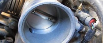
The air filter is located in the front part of the engine and is equipped with rubber retaining elements. If it becomes necessary to replace them, the corrugation is located on the same parallel with the center line of the car. The main function of the throttle pipe is determined by dosing the air flow entering the intake pipe. The air entering the engine is adjusted thanks to the throttle valve, which is connected to the accelerator pedal. The throttle pipe consists of two components: the throttle position sensor and the idle speed control.
Source
How to connect wires correctly
When replacing high-voltage conductors, they are first connected to the ignition distributor. The distributor cover is convenient in that it is always installed in one position. There is a special mark on it, thanks to which it will not be difficult to place the part in place. Before connecting the wires, inspect the cover. It must be intact, since if cracks appear, the performance of this unit is not guaranteed.
The mark on the distributor cover is located next to the wire socket of the first cylinder. The firing order of the cylinders is slightly out of order (1-3-4-2) due to the ignition slider. It moves around the circle (distributor) counterclockwise. It is precisely by this principle of movement of the slider that it is easy to remember the order of the wires. They need to be connected to carburetor and injection VAZ-2109 according to the same principle. On the distributor cover, connect the wires according to the principle of movement of the slider, this is the only way you can set the ignition correctly:
- the socket of the first cylinder is located at the mark;
- the third one is connected at the very bottom;
- on the same line with the socket of the first, there is a place for the wire to the 4th cylinder;
- at the top point the second cylinder is connected.
On the engine itself, the cylinder numbering goes from the location of the timing belt to the starter, that is, from left to right. The fourth cylinder is closest to the starter, and the first is closest to the timing belt. When connecting, it is important to look at which socket of the distributor cover the wire comes from, if you confuse their location, the car will not start.
If you have connected the wires correctly, but the car still does not start, then the problem may be in them. Check high-voltage conductors for integrity. If you haven't changed them in a while, it's worth buying a new set. The peculiarity of these wires is that over time microcracks can form on their surface. They lead to a lack of spark when the ignition distribution system is working. Moisture and dust get into these cracks, which damages the wire from the inside, although it appears intact from the outside.
Car enthusiasts recommend purchasing sets of high-voltage wires from foreign manufacturers, as they last much longer than stock or domestic ones. It is advisable to replace the spark plugs along with the wires, especially if cracks or carbon deposits appear on their surface. This is necessary so that after repair you definitely do not have problems with ignition.
Numbering of cylinders in different types of internal combustion engines
As for the standards for numbering combustion chambers, there are none. The way they are numbered in the internal combustion engine is influenced by the following factors:
- Type of drive;
- ICE type, block layout;
- Transverse or longitudinal arrangement of the unit under the hood;
- Side of rotation.
On standard front-wheel drive cars with a transversely mounted engine, the numbering begins on the timing side. So, near the timing belt there is the first cylinder and then all the others. The latter is located near the checkpoint.
Examples
In multi-cylinder V-twin engines, the first cylinder is located in the bank on the driver's side.
In American-made engines, the combustion chambers and their numbering may differ and defy logic.
So, for in-line fours and sixes, the first cylinder may be near the radiator, while on all other models the numbering begins towards the interior. If the numbering is reversed, then the cylinder closest to the passenger compartment is considered first.
Note: How to remove a hernia on a car wheel and why it is dangerous
The French are very original and use two methods of numbering the combustion chambers of internal combustion engines.
- On inline fours, the numbering starts from the flywheel.
- If it is a V-shaped six, then the row closest to the radiator is the first three cylinders, and the row closer to the passenger compartment is the last three.
The design of the injection 8-valve VAZ-2114 engine
Many motorists, especially beginners who have just purchased a VAZ-2114, have wondered how the 8-valve injection engine that is installed on this car works. This article will discuss the design of the motor, its main characteristics, as well as dismantling and repair features. This information will be very useful for beginners and those who do not know how the main power unit works.
Video about the VAZ-2114 engine
Video review of the VAZ-2114 engine operation, features and characteristics.
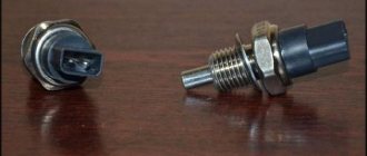
Speed sensor
The operating principle of the speed sensor (DS) is based on the Hall effect. The sensor outputs voltage pulses to the controller with a frequency proportional to the rotation speed of the drive wheels. Speed sensors differ in the connection connectors to the harness block. The square connector is used in BOSCH systems.
The sensor with a round connector is used in the January 4 and GM systems. All sensors are 6-pulse, that is, they produce 6 pulses per revolution of their axis. The 10-pulse sensor is used for Samara carburetor trip computers. The speed sensor signal is used by the control system to determine the fuel cut-off thresholds, as well as to electronically limit the vehicle speed (in new control systems).
In those models that have one, you need to install the speedometer drive into the gearbox very carefully; at the slightest misalignment, the plastic teeth of the speedometer drive drive gear will wrinkle and complete disassembly of the gearbox is inevitable.
When the speedometer needle begins to spontaneously deviate within a fairly wide range, regardless of speed, it’s time to change the speed sensor.
The output voltage of the low level pulse should be no more than 1V, and the high level pulse should be no less than 5V.
Engine diagram and structure
General view of the engine
Before we begin to consider the issue of the engine design and description of the characteristics, it is necessary to consider the design of the components and parts that are located directly in the main power unit and outside.
Diagram and design of the Samara-2 engine
1 – generator drive pulley; 2 – oil pump; 3 – timing belt; 4 – toothed pulley of the coolant pump; 5 – front cover of the timing mechanism drive; 6 – tension roller; 7 – camshaft toothed pulley; 8 – rear cover of the camshaft drive; 9 – camshaft oil seal; 10 – cylinder head cover; 11 – camshaft; 12 – front cover of camshaft bearings; 13 – pusher; 14 – valve guide; 15 – oil separator mesh for the crankcase ventilation system; 16 – exhaust valve; 17 – inlet valve; 18 – rear cover of camshaft bearings; 19 – fuel pump; 20 – housing of auxiliary units; 21 – ignition distributor sensor; 22 – outlet pipe of the cooling jacket; 23 – cylinder head; 24 – spark plug; 25 – crankcase ventilation hose; 26 – flywheel; 27 – crankshaft rear oil seal holder; 28 – rear crankshaft oil seal; 29 – cylinder block; 30 – oil pan; 31 – oil level indicator (oil dipstick); 32 – crankshaft; 33 – piston; 34 – connecting rod cover; 35 – connecting rod; 36 – crankshaft main bearing cover; 37 – front crankshaft oil seal; 38 – crankshaft toothed pulley.
Also, it’s worth looking at a cross-section of the VAZ-2114 engine:
Cross section of the Samara engine
1 – oil pan drain plug; 2 – oil pan; 3 – oil filter; 4 – coolant pump; 5 – exhaust manifold; 6 – intake manifold; 7 – carburetor; 8 – fuel pump; 9 – cylinder head cover; 10 – camshaft bearing cover; 11 – camshaft; 12 – crankcase ventilation hose; 13 – valve adjusting washer; 14 – pusher; 15 – valve cotters; 16 – valve springs; 17 – oil scraper cap; 18 – valve guide; 19 – valve; 20 – cylinder head; 21 – spark plug; 22 – piston; 23 – compression piston rings; 24 – oil scraper ring; 25 – piston pin; 26 – cylinder block; 27 – connecting rod; 28 – crankshaft; 29 – connecting rod cover; 30 – oil level indicator; 31 – oil pump receiver
Characteristics of an 8-valve engine
Many motorists remember how at the end of the 90s of the 20th century and the beginning of the 2000s, the VAZ 2108-09, which was also called “Samara,” was popular on the roads of the CIS. These cars became legendary in that era. Due to the high popularity, the AvtoVAZ plant decided to resume production of these models with some modifications.
VAZ-2114 engine under the hood
Firstly, the VAZ-2114 received a modified engine . In essence, this is an injection version of the Samara. Although it received some features from modern engines. If we consider in more detail, the Samara-2 engine (this is the type installed on the VAZ-2114) is a mixture of two engine options into one: from the VAZ 2108 and VAZ 2110.
Many motorists liked the Samara-2 power unit and fell in love with it. The main indicator was ease of repair and inexpensive spare parts. Thus, the 8-valve engine has become the standard for “price-quality” indicator.
When the basic information has been reviewed, you can proceed directly to considering the characteristics of the motor.
Table of main characteristics of the Samara-2 engine 8 valves:
Disassembly and repair: basic facts
Let's consider this paragraph of the article as reference information, because if we talk about engine repair, then each individual component and unit is repaired separately. When operating the power unit, it may be necessary to dismantle it. In this case, you can consider replacing the power unit from a foreign car.
Therefore, let’s consider the main operations aimed at removing the engine from the car:
- At the preliminary disassembly stage, it is necessary to drain the oil from the engine, as well as the coolant from the system.
- Another point that should not be missed is turning off the power to the car. This is necessary in order not to short-circuit the system.
- Disconnect the fuel system.
- We dismantle the components that supply air to the engine.
- Disconnect the throttle, as well as all remaining air pipes and cooling system pipes.
- We dismantle the injection system and receiver.
- We remove the ignition system completely.
- Let's disassemble the gas distribution mechanism.
- We remove the thermostat and pump.
- Remove the ignition module.
- Now, you can dismantle the collector.
- Remove the pan, oil filter and pump.
- Disconnect the gearbox and remove the clutch. The gearbox can also be removed for convenience.
- Remove the cylinder head.
- We dismantle the power unit.
- We carry out final disassembly.
Characteristics of motors 2114
Since the release of the Lada Samara VAZ-2114, the technical characteristics of the gasoline drive have been constantly improved. Owners of domestic cars, in principle, do not have questions about what kind of oil to pour into the engine, since standard requirements apply for Zhiguli, Lada and Samara - 5W30 or 10W30.
In addition, you should know what kind of oil to use in transmission gears - the instructions from the AvtoVAZ manufacturer recommend using the GL-4 group of lubricants with a viscosity of 80W85 (mineral), 75W90T (synthetic) or 85W90 (semi-synthetic).
After filling with synthetics, the box becomes noisy, the oil is more expensive, but the lubricant is mostly imported, which provides additional guarantees. Domestic manufacturers most often produce semi-synthetics of average quality for engines and transmission gearboxes.
The technical characteristics of the engine are as follows:
| Characteristics | Engine modification | ||||||||
| 2111 | 21114 | 11183 | 21124 | 21126 | |||||
| Years of installation | 2003 – 2007 | 2003 – 2007 | 2007 – 2009 | 2009 – 2013 | 2009 – 2013 | ||||
| Volume | 1500 cm 3 (1.5 l) | 1596 cm 3 (1.6 l) | 1596 cm 3 (1.6 l) | 1599 cm 3 (1.6 l) | 1597 cm 3 (1.6 l) | ||||
| Power | 56.4 kW (77 hp) | 59.5 kW (81.6 hp) | 59.5 kW (82 hp) | 65.5 kW (89.1 hp) | 72 kW (97.9 hp) | ||||
| Torque moment | 115.7 Nm (3200 rpm) | 125 Nm (3000 rpm) | 120 Nm (3200 rpm) | 131 Nm (3700 rpm) | 145 Nm (4000 rpm) | ||||
| Weight | 127.3 kg | 112 kg | 112 kg | 121 kg | 115 kg | ||||
| Compression ratio | 9,8 | 9,6 | 9,6 | 10,3 | 11 | ||||
| Nutrition | injector | ||||||||
| Engine diagram | Inline (L) | ||||||||
| Ignition | module | coil | coil | coil for each spark plug | |||||
| Number of cylinders | 4 | ||||||||
| Location of the first cylinder | TVE | ||||||||
| Number of valves on each cylinder | 2 | 2 | 2 | 4 | 4 | ||||
| Cylinder head material | aluminum alloy | ||||||||
| Intake manifold | aluminum | plastic with receiver | |||||||
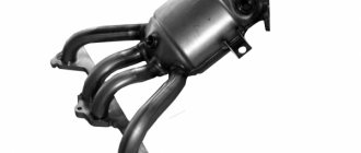
| An exhaust manifold | with catalyst | ||||||||
| Camshaft | 2110 | 2111 | 2112 | ||||||
| Cylinder diameter | 82 mm | ||||||||
| Piston stroke | 71 mm | 75.6 mm | |||||||
| Pistons | Yes | No | No | Yes | No | ||||
| Valve bend | Yes | No | No | Yes | No | ||||
| Crankshaft | 2112 | 11183 | |||||||
| Fuel | AI-95 | ||||||||
| Environmental standards | Euro 4 | Euro 2 – 4 | Euro 3 – 4 | ||||||
| Fuel consumption highway/combined cycle/city | 5,7/7,3/10 | 6/7,3/10,4 | 6/7,8/11 | 5/7/9,5 | 5,4/7,2/9,8 | ||||
| Oil consumption per 1000 km | 0,7 | 0,5 | |||||||
| Engine oil for 2114 | 5W-30 and 10W-30 | ||||||||
| Engine oil volume | 4 l | 3.8 l | 3.5 l | 3.6 l | |||||
| Operating temperature | 95° | ||||||||
| Motor life | declared 150,000 km, real 250,000 km | ||||||||
| Adjustment of valves | washers between camshaft cams and tappets | hydraulic pushers | |||||||
| Cooling system | forced, antifreeze/antifreeze | ||||||||
| Coolant quantity | 7.8 l | ||||||||
| water pump | plastic impeller | ||||||||
| Candles for 2114 | A17DVRM, BPR6ES | AU17DVRM, BCPR6ES | |||||||
| Gap between spark plug electrodes | 1.1 mm | ||||||||
| Timing belt | length 698 – 1125 mm depending on attachments | ||||||||
| Cylinder operating order | 1-3-4-2 | ||||||||
| Air filter | Nitto, Knecht, Fram, WIX, Hengst | ||||||||
| Oil filter | Mann W914/2 | ||||||||
| Flywheel | 2110 | ||||||||
| Flywheel mounting bolts | M10x1.25 mm, length 26 mm | ||||||||
| Valve stem seals | code 90913-02090 inlet light code 90913-02088 exhaust dark | ||||||||
| Compression | from 14 bar | ||||||||
| XX speed | 750 – 800 | 800 – 850 | |||||||
| Tightening force of threaded connections | spark plug – 31 – 39 Nm flywheel – 61 – 87 Nm clutch bolt – 54 – 87 Nm bearing cap – 59 Nm (main) and 43 – 53 Nm (rod) cylinder head – four stages 20 Nm, 71 Nm + 90° + 90° For high-quality maintenance of internal combustion engines, the engine manufacturer issues a manual containing a description of the drive parameters, the frequency of replacing consumables and step-by-step repair operations. The same operating manual recommends the volume of oil in the gearboxes in the engine. | ||||||||
Operating procedure
Often when repairing an engine, it becomes necessary to disconnect high-voltage wires. Some drivers, after disconnecting the wires, do not remember the order in which they were installed. As a result, there may be confusion with the wires, and if they are connected incorrectly, the car will not start. To avoid an unpleasant situation, you need to know how the internal combustion engine operates.
Connecting wires to a VAZ 2109
The principle of operation of the power unit is based on such a property of gases as the ability to expand when heated. A standard four-cylinder engine operates in 4 strokes:
- During the first stroke, the air-fuel mixture and part of the exhaust gases are “injected”. This mixture completely occupies the volume of the cylinder.
- In the second cycle, the “compression” process occurs. In this case, the valves are closed, and the piston moves upward due to the movement of the crankshaft and connecting rod. The working mixture fills the combustion chamber.
- On the third stroke, called “expansion,” a spark appears thanks to the spark plugs, which ignites the working mixture. The expanding gases exert pressure on the piston and force it to move downward. Then, thanks to the connecting rod, the crankshaft begins to move.
- On the fourth stroke, the process of “release” of exhaust gases is carried out. Through the exhaust valves they enter the exhaust system of the VAZ 2109.
In order for the operation of a multi-cylinder engine to be smooth and the crankshaft not to experience uneven loads, it is necessary that the work processes be carried out in a certain order.
There are different schemes that determine in what sequence the cylinders will function. The VAZ 2109 uses the following scheme: 1-3-4-2. The cylinders are numbered starting from the front cover of the power unit.
Cylinder numbering on the VAZ 2109
If we imagine the working process of the engine through the cylinders, then the order of operation is as follows:
- In the first cylinder, an upward movement occurs, the working process takes place: the air-fuel mixture burns, the gases expand.
- In the third, a “compression” process is carried out, in which the piston moves upward.
- The fourth receives the working mixture as the piston moves downwards, thus carrying out the “injection” process.
- In the second, the piston moves upward, while the exhaust gases exit through the exhaust valves.
Maintenance schedule
To avoid having to carry out expensive overhauls of the Lada Samara 2114 yourself, you should follow the manufacturer’s recommendations for servicing the internal combustion engine:
Timing belt replacement after 100,000 km Battery 1 year/20,000 Valve clearance 2 years/20,000 Crankcase ventilation 2 years/20,000 Belts driving attachments 2 years/20,000 Fuel line and tank cap 2 years/40,000 Motor oil 1 year/10,000 Oil filter 1 year/10,000 Filter air 1 – 2 years/40000 Fuel filter 4 years/40000 Fittings and heating/cooling hoses2 years/40000Coolant2 years/40000Oxygen sensor100000Spark plug1 – 2 years/20000Exhaust manifold1 yearIf consumables are replaced within the recommended time frame, the operational life of the internal combustion engine will increase.
Possible causes of failure
During the operation of the internal combustion engine, various malfunctions are possible. To detect them, you should perform the following sequence of actions:
- First you need to start the car. The engine should idle. At this time, you should listen to what sounds are coming from the exhaust pipe. If you hear regular popping noises, then one of the cylinders is faulty. The cause may be faulty spark plugs and lack of spark. The malfunction can also be caused by a large amount of incoming air or insufficient compression in the cylinder.
- It is necessary to inspect the candles. If there is carbon deposits, moisture or oxidation, you need to clean it. Check the gap between the electrodes, which should be 0.8 - 0.9 mm.
- Replace all spark plugs, regardless of their appearance and vehicle mileage.
- If there are irregular emissions, you need to inspect the high-voltage wires. There should be no traces of oxidation on their tips, and the insulation should not be damaged. If defects are found, the wire should be replaced.
Wires connecting to the coil
- The gas distributor cap should be inspected. There should be no soot or cracks on it. The carbon contact should be checked for damage and wear.
- The rotor needs to be inspected. It must be solid and have no signs of burnout. All parts with defects must be replaced.
- The pressure in the cylinders is allowed to be no lower than 1.1 MPa, and the compression difference should not exceed 0.1 MPa. If the indicators do not correspond, engine repair is necessary.
If after the above steps the problems remain, then you need to contact a service station to undergo a more accurate diagnosis of the VAZ 2109 engine and adjust the ignition system on the stand.
A little history
In the period from 1980 to 1984, AvtoVAZ worked quite closely with the giant of the modern automotive industry - Porsche.
At that time, joint work was underway on the VAZ 2108 model. Already in the period from 1987 to 1991, the companies began working on a new car - the VAZ 2110 with a 1.5-liter engine.
Despite the cooperation agreement regarding only these two models, specialists did not miss the opportunity to work on the entire line being developed at that time. This also applied to the VAZ 2109 model, which became the successor to the modern fourteenth.
Not everyone knows about this fact of cooperation with a German company, which was already considered a model of the automotive industry. But this is precisely what served as a springboard for the creation of reliable and very interesting domestic cars.
Large-scale production of the successor to the Russian-German “nine” in the person of the VAZ 2114 began in 2003. It is noteworthy that first, in 2001, the VAZ 2115 appeared, and in 2004, the VAZ 2113.
According to research, the VAZ 2114 is on the list of the most common models in Russia.
Differences from the “nine”
There are not so many differences between the VAZ 2114 and VAZ 2109 in terms of bodywork. The updated car received new:
- Front part of the body;
- New lens shape;
- New hood;
- Different radiator grille;
- Improved quality of plastic on bumpers;
- Spoiler;
- Moldings;
- Threshold covers.
There were much more changes inside. But in many ways the difference is determined by the class of the car, that is, its equipment. For the VAZ 2114 there were three equipment options - Standard, Norma and Lux.
So what has changed inside?
- There was a new dashboard with a dashboard without an upper glove compartment. The Lux package has a recessed part. There are a pair of cup holders on the lower glove compartment lid.
- The Norma and Lux trim levels are equipped with electric windows.
- The steering wheel is adjustable for tilt. It is noteworthy that the steering wheel of the VAZ 2114 and the steering column are taken from a dozen.
- Seat belt fasteners are also taken from dozens.
- The dashboard is used from the fifteenth VAZ model.
- An adjustable interior light is located on the ceiling.
- The maximum configuration has a full-fledged on-board computer.
- The stove became more powerful, but this increased the noise level.
Key Benefits
Obviously, the fourteenth model from AvtoVAZ is not as simple as many people think at first glance. Otherwise, it simply would not have been so popular and in demand.
Here's an example of a few of the most significant benefits.
- Excellent aerodynamics. Considering the power of the engines and the aerodynamic capabilities of the body, this is one of the best models created for high-speed driving. Carry out chip tuning to increase engine power or organize more serious modifications to the engine, and you can extract good horsepower. In this case, the engine resource will not be particularly affected.
- Great looks. Obviously, the VAZ 2114 looks much more interesting and attractive than the Nine. At the same time, the model was literally created for tuning. It is not necessary to increase power. An original body kit - and you are a road star. But in everything you need to know when to stop, so as not to turn real tuning into a collective farm.
- Youth orientation. The younger generation of drivers was unlikely to be very interested in sevens, tens or sixes from AvtoVAZ. Yes, they were cheap and were bought most often due to the lack of alternatives. But with the advent of the VAZ 2114, many realized that a beautiful, domestic car had finally come out, which looked no worse than its imported sporty counterparts. At the same time, in terms of prices they could not compete even close to the fourteenth.
- Possibility of improvements. Until now, for the VAZ 2114, despite the model being discontinued, many elements are available for external and internal tuning. Body kits, trims, moldings, spoilers, seats, optics - everything to suit your taste and budget. What’s most interesting is that for little money you can organize a large-scale modification, changing the standard VAZ 2114 beyond recognition.