It would seem that there is something wrong here - there is not enough tension. The car runs on gasoline, not electricity. However, a lack of current power leads to an increase in fuel consumption, a decrease in engine power, and some electrical appliances stop working altogether and will require replacement in the future. This is especially noticeable in the dark, when many power supply devices are used.
The first sign of lack of voltage is dim high beams - their lamps require a large number of watts. In most cases, it turns out that the battery is poorly charged.
You can deal with this problem easily and quickly by charging it properly. However, sometimes this doesn't help. Look under the hood - the battery terminals may be loose or oxidized. If in a parking lot the current still maintains a constant voltage, then during driving, due to vibration, the terminals may move away, opening the circuit. To fix the problem, you need to thoroughly lubricate the fasteners and tighten the bolts; sometimes only replacing the old terminals with new ones will help.
How does a voltage regulator work?
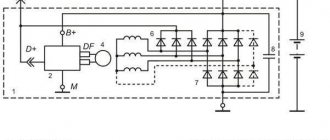
In terms of its design, the three-level voltage regulator VAZ 2114 is a relay with a transistor circuit and resistances connected to it, which, in turn, are connected to the exciting winding on the generator stator.
The principle of its operation is as follows - during its operation, the generator produces current with an unstable, intermittent voltage, the use of which directly in the on-board network could lead to malfunctions and even breakdowns of electronic equipment. In order to eliminate these surges and maintain the voltage produced by the generator at the same level, a stabilizer regulator is needed.
So, when generating too high a voltage, the device includes additional resistors in the circuit, which lower the voltage to the desired level. Otherwise (when the voltage is too low), the stabilizer turns off all resistance in the circuit, and the voltage produced by the generator increases.
Speaking about the operation of the stabilizer, one should also take into account the fact that all these adjustment voltage fluctuations occur at a high frequency, as a result of which the total voltage in the on-board network remains virtually unchanged.
In simple terms, the voltage regulator of the VAZ 2114 generator is responsible for:
- activation of the electric generator;
- control of the current supplied by the generator;
- maintaining the voltage supplied to the on-board network at a stable level.
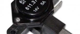
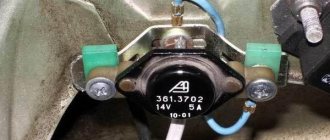
For the regulator mounted on the 14th model, the standard operating parameters are a nominal voltage of 14.5 volts and a nominal current of 5 amperes.
Operation, modifications and replacement of the voltage regulator on the VAZ 2114
Standard voltage regulators for the VAZ 2114 have a feature that is associated with the fact that it is assembled with a brush holder. Despite the fact that these two devices perform different functions, they are assembled into an integral device and if one of them fails, the entire set has to be removed.
A signal for checking and replacing the LV can be a low voltage on the VAZ 2114 on-board network or a drop in the level of illumination by the headlights. This can be determined by observing the capacity of the on-board battery. When the voltage supplied by the generator drops, the battery is poorly charged and the battery capacity drops. If, when monitoring the pH on a cold engine, the voltage is significantly lower than 14.6 V, then the regulator needs to be replaced.
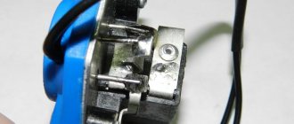
At the same time, if the LV is in good condition, and when checking the brush assembly it is determined that the brushes are worn out or burnt, then the entire assembly will have to be replaced. This must be done if they protrude from the brush holder by less than 5 mm.
Replacing the VAZ 2114 voltage regulator is possible with your own hands. This process is relatively simple, but requires a careful approach.
Attention! The electrical parts of the vehicle must be kept clean. Any contamination leads to a decrease in the performance of the electrical part.
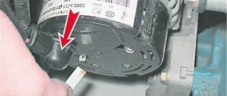
Location of the voltage regulator on the VAZ 2114 generator
There is open access to where the voltage regulator is located on the VAZ 2114 and nothing interferes with the work. The LV is located under the plastic cover of the generator, which covers the entire contact group of this electrical unit.
- Before starting work, you must disconnect the contact wires from the battery.
When working with electrical equipment on a car, the battery must be disconnected to prevent voltage surges or short circuits, which could result in damage to important devices or a fire.
- Then you need to find a contact drive with a block that fits onto the output of the generator “D”. This block needs to be disconnected.
- Remove the protective rubber cap from the “+” terminal. Using a “13” key, unscrew the nut that secures the external wires to the contact pin and remove them from the pin.
- Unscrew the three clips on the sides of the plastic cover and remove it. In this case, you need to help with a flat screwdriver to press its edges around the circumference from the area of contact with the generator housing.
- The voltage regulator is secured with two screws. You need to unscrew them using a Phillips screwdriver.
- Disconnect the connector of wires leading to the LV and pull out the regulator body along with the brushes.
- Installation of a new LV is performed in the reverse order. In this case, it is necessary to thoroughly clean all contacts and check the tightness of their fastening, otherwise the performance of this device may be incorrect.
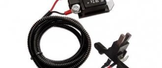
In addition to standard regulators, the use of other devices that support the specified characteristics is allowed. Such devices include a thermally optimized RENATO LV and a three-level voltage regulator.
- The RENATO pH regulates charging within a voltage range of 13.6 - 14.7 V, depending on the temperature of the electrolyte in the battery. The temperature sensor is installed on the battery and connected by a wire to the LV. Sold complete with regulator.
- The three-level pH is designed to extend the battery life. In addition, it ensures optimal generator voltage under different operating conditions and, accordingly, more efficient operation of lighting equipment and the heating system of the machine.
Three-level voltage regulator for VAZ 2114
The design of this device includes a three-position switch with several positions and, accordingly, modes:
- in the minimum position, designated as “min”, a voltage of 13.6 V is maintained. This position is designed for operation in difficult conditions - at high air temperatures, more than plus 20 degrees, long periods of uphill driving or in traffic jams;
- in the middle position of the switch, designated “norm”, the voltage corresponds to 14.2 V. This mode provides for the generator to operate with a warm engine and an ambient temperature from zero to plus twenty degrees;
- when the switch is set to “max”, the pH maintains the voltage within 14.6 - 14.7 V. This mode is required during a cold start, engine operation at low temperatures and at full load from switched on consumers.
A factory-made three-level launch vehicle can be installed without much difficulty. A new brush holder is inserted in place of the old regulator, and the wiring from it is passed through the plastic cover of the generator. The new device is mounted on the engine compartment body in any convenient place and ensures reliable contact to ground. The wire connecting the device itself and the brushes must be insulated from high-voltage wires and the machine body. For more information on how to install a 3-level regulator, we suggest watching the video:
Installation and connection instructions
For Lada cars (except Vesta, XRAY)
, photo author:
1.
Remove the generator.
2.
Remove the plastic casing of the generator. To do this, first disconnect the generator excitation wire. Then unscrew the nut from the stud (10mm wrench) and move the power wire to the side. Next, 3 latches on the plastic casing are unfastened.
3.
Remove the standard voltage regulator from the generator. To do this, unscrew two screws ("8" key) and disconnect the wire.
4.
Install a three-level voltage regulator on the generator instead of the standard one.
5.
Output 2 wires for the control module. The module itself should be mounted in conditions of reliable contact with the “ground” and as far as possible from the possibility of moisture ingress. For example, on a hairpin near the right headlight.
For Lada Vesta, XRAY cars (with Valeo TG12C209 generator).
This generator is no different from the previous ones, the only difference is in the voltage regulator. It communicates with the engine ECU via a “lin” interface. The task of this “lin” is to avoid loss of throttle response at power modes. By installing the TRN, we cut off the ability to control the regulator using the ECU!
For this generator there is no ready-made solution in the form of a TRN yet, so the design will have to be modified.
- three-level voltage regulator (article 67.3702-01)
- 2-pin block 904576 NORD YADA
- generator voltage regulator (leave the standard one (if the brushes are live) or ARV1103AD)
- wire for powering the regulator (2 meters)
2.
Remove the voltage regulator, open the cover and clean everything under it. Reinstall the cover.
3.
Isolate the negative brush from ground (for example, drill out the negative outlet, place washers). It is necessary to completely eliminate contact between the regulator and the generator.
4.
Solder the female connector to the brushes.
5.
Solder the male connector to the 3-level regulator. Also, connect an additional wire to the positive output, which is needed to power the regulator and rotor.
- Output “Ш” on the regulator goes to the negative brush.
- Output “+” - to the positive brush.
The “+” output needs to be supplied with 12V, which appears when the ignition is turned on:
Carrying out diagnostics of RN with your own hands
Now we’ll tell you how to check a three-level voltage regulator with your own hands. The procedure for checking the regulator can be carried out both at a service station and in a garage, but we will consider the second option. Testing a voltage regulator of 40 amps or less should be done using a tester - a voltmeter or a multimeter. It should also be taken into account that fault detection in the operation of the launch vehicle should be carried out exclusively with a fully charged battery.
So, how to check the generator voltage regulator using a tester:
- First of all, you need to open the hood and turn the key in the lock, turning on the ignition.
- Next, the power unit is started. The engine should idle for some time; to obtain more accurate diagnostic data, it is recommended to turn on the optics. The engine speed when running should be around 2.5-3 thousand. For the internal combustion engine to switch to this operating mode, you usually need to wait about 10 minutes.
- Then the tester probes are connected to the battery terminals. When you connect the tester, diagnostic indicators should appear on its display, ideally they should be approximately 14.1-14.3 volts.
If the check shows other values, be they higher or lower, then you need to start repairing the generator unit. But as practice shows, the problem usually lies precisely in the launch vehicle, so most likely it will have to be replaced. Before you begin diagnostics, make sure that the belt is properly tensioned . During diagnostics, contacts must not be closed, as this may cause deformation and failure of the rectifier unit.
How does a three-level voltage regulator work?
And so, we have already found out that three-level voltage regulators, together with the entire installation kit, are intended to automatically maintain voltage at the terminals of a car alternator. Such devices are mounted on vehicles, the generator windings of which are connected to the positive circuit. In addition, there is another type of three-level regulator, the kit of which, in addition to standard components, also includes a set of brushes or an integral unit with wiring. The regulator itself is mounted directly on board the machine, and the brush assembly (or panel with wiring) is mounted into the generator.
About the compatibility of voltage regulators and VAZ generators
Depending on the generator, installation of a new type of voltage regulator can be done without modifications, or it may require replacing the terminals on terminals “B+” and “D+” and modifying the diode bridge of the generator.
A simple replacement of the LV without modifications can be carried out on generators:
- – 372.3701 installation RN 1702.3702-01 – VTN.
- – 9402.3701/3202.3771 installation RN 9111.3702 – VTN, 9111.3702I2 – VTN, or 9333.3702-02 – VTN.
- – 5102.3771 installation RN 846.3702 – Orbit.
Examination
1. Inspecting the brushes of the voltage regulator, we make sure that they are mobile. If the brushes are broken or badly worn (protrude no more than 5 mm
), or they get stuck in the brush holder, the regulator needs to be replaced.
2. To check the voltage regulator, we assemble a circuit (see below). We connect the test lamp to the regulator brushes. We connect the negative terminal of the power source to the “ground” of the regulator, and the positive terminal to its terminal.
Warning! When connecting the wires supplying voltage to the voltage regulator, strictly observe the polarity. Incorrect connection of the wires will damage a working regulator.
Using a voltmeter we monitor the voltage supplied to the regulator.
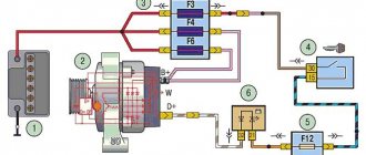
Voltage regulator test circuit:
1 — multimeter (in voltmeter mode); 2 - control lamp; 3 — “mass” of the regulator; 4 — regulator output; 5 - brushes
3. Turn on the power supply and supply 13 V to the regulator. The control lamp should light up, indicating that at this voltage in the vehicle's on-board network, the excitation current will flow to the generator rotor winding.
4. Gradually increase the voltage until the control lamp goes out. The voltage at which the control lamp goes out should be 14.5-14.7 V.
5. Reduce the supplied voltage until the control lamp lights up again. The voltage at which the control lamp turns on should not be lower than 13.2 V.
We replace the faulty voltage regulator.
Signs of regulator malfunction
Sometimes during the operation of a car it happens that the stabilizer fails. Signs of this may include frequent fluctuations and sudden surges in voltage in the vehicle network, problems with electrical appliances and rapid discharge of the battery. If you notice one or more of the above signs, then the relay regulator of the VAZ 2114 generator should be tested using a multimeter.
Checking the voltage regulator VAZ 2114
You can do this as follows:
- Set the tester to measure DC voltage with a limit of 20 volts.
- Measure the voltage readings at the battery terminals with the engine turned off (the result should be from 12.5 to 13 volts).
- Start the engine and measure the voltage at the terminals again (now it should be between 14 and 14.5 volts).
- Without turning off the engine, turn on the high beam, heater and heated glass (other powerful consumers can also be used). Measure the voltage on the battery a third time. The voltage readings should be in the range of 13.2-13.9 volts - this will mean that the stabilizer is fixed. Otherwise, the device will have to be dismantled and replaced.
Traveling in a car with a faulty generator regulator is not profitable and even unsafe, as this can lead to increased fuel consumption, breakdowns in the on-board network, and even a car fire.
You can check the correct operation of the regulator without using a multimeter, with the device removed. To do this, you need to connect its “ground” terminal to the negative of the battery, and connect contacts B and C to the positive. After this, you should take a 3-watt car lamp and connect it to the graphite brushes of the regulator. If the latter is working properly, the lamp will light up.
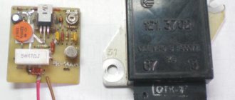
New and damaged voltage regulator
In some cases, you can go even further and check the trigger threshold. To do this, the regulator should be connected as mentioned above, but between its positive terminals and the plus of the battery, connect a pair of AA batteries in parallel in order to increase the voltage in the network to 16 volts. If the regulator is working correctly, it will interrupt the power supply and the light bulb connected to its brushes will not light up.
Bearing sizes and manufacturers
Before replacing a bearing with a new standard product, you need to buy it. The marking of these standard consumables is complex; the numbers in it are deciphered using special tables. Moreover, bearing designations according to GOST 3189 do not coincide with the markings of foreign manufacturers, so the user needs to know the following nuances:
- the marking consists of three parts (main, left, right), and blocks inside them;
- in the left and main parts the blocks are located from right to left, and in the right block on the contrary, from left to right;
- in cars, the front bearing of the generator most often has the designation of the main part 302 or 303, and the rear bearing 202 or 203;
- usually radial ball modifications with code 0 (0302 or 0202) or angular contact balls with code 6 (6303 and 6203) are used;
- therefore, for the specified parameters, you can decipher the dimensions using the table below;
- For foreign-made bearings, similar markings are used.
This is interesting: What kind of bulbs are in the foglights on the Hyundai Solaris
Marking of bearings according to GOST 3189
Table for deciphering bearing sizes by marking
Designation of imported bearings
The suffix (right side of the marking) of imported bearings contains additional information. For example, letters and numbers can represent:
- 2RS and RS – double-sided and single-sided rubber seals, respectively;
- N and NR – groove on the outer ring without a latch and with a latch, respectively;
- J – steel holder;
- Z – sheet protection on one side without seals.
The main problem for a car enthusiast when doing self-repair is the variety of bearing sizes inside the generator:
- it is difficult to guess the markings before disassembling, when the car is still running;
- after dismantling and disassembling the generator, the dimensions and markings are known to the owner, but he has to go to the store in a different car;
- in some stores, sellers practice a convenient system - the car owner takes 4 bearings 202, 203, 302 and 303, and returns two of them back.
These modifications have dimensions:
Replacement
The process of replacing old brushes with new ones does not take much time and does not require special knowledge. The only thing you need to prepare are the tools:
- socket wrench 13;
- flat screwdriver (ordinary);
- 8mm socket with ratchet.
Without removing the generator
If you are sure that the problem with the car breakdown is a malfunction of the generator brushes, then you can do without removing it.
- Turn off the negative terminal.
- Disconnect the wires.
- On the brush holder body, unscrew the two bolts holding it in place.
- We extract the structure.
- We check for damage and the size of the protruding part of the brushes (it must be at least 5mm).
- We install new elements and carry out installation in the reverse order.
With the generator removed
Poor charging of the car can be caused not only by the brushes, but also by the alternator belt. To eliminate this point, when replacing brushes, you should remove it to check the condition of the belt.
First, we dismantle the unit.
REPLACING THE REGULATOR WITH A NEW OWNER ON YOUR OWN
Now we need to figure out how to replace the VAZ 2114 voltage regulator. First, you need to understand that it itself is located inside the generator housing. Mechanically, it consists of a special armature, an electromagnet and a relay. To disassemble the generator and remove the regulator we will need the following necessary tools:
- Set of open-end wrenches;
- Various screwdrivers.
Typically, repairs involve a complete replacement, but the generator itself does not need to be completely removed from the car. However, first you need to remember to remove the terminals from the battery, 12 V is not much, but it will be unpleasant to get hit. After the car has been de-energized, you need to remove the caps from the generator terminals and unscrew them with a screwdriver. Now you need to carefully remove the protective casing from the generator; on the VAZ 2114 it is equipped with spring latches; it is important not to break them right away. Now the voltage regulator of the VAZ 2114 generator will be visible under the casing; you need to unscrew its fastenings and pull it out of the seats along with the brushes.
The next phase of our work will be to check its functionality. Now let’s figure out how to understand that the voltage regulator is not working, for this we will need the following components:
- Accumulator battery;
- Miscellaneous wires;
- An ordinary 12 volt lamp, anything from the car's network will do.
You need to immediately understand that checking the regulator should be carried out only together with the brushes.
The light bulb itself must be connected via wires to the generator brushes; the polarity of the wires does not matter. Now you need to figure out where the negative terminal of the battery is and connect it to the relay body, and the second one must be connected to the regulator terminals. If everything is done correctly, then the bright light from the light bulb will be a sure sign that all elements are working properly. You also need to know that testing the functionality of a new regulator is carried out in exactly the same way. After the repair is completed, everything must be assembled strictly in the reverse order, and it is advisable to charge the battery during the repair so that it does not lose its charge.
How to remove a generator on a VAZ 2107 Everything is as simple as shelling pears
- Keys 10, 17, 19;
- Set of heads;
- Ratchet;
- Mount;
- Hammer and punch.
First, remove the chips from the generator. The wire to terminal “30” is secured with a nut; unscrew it using a 10-mm open-end wrench; Using a 17 key, loosen the adjustment bar and press the “gene” to the cylinder block. Usually this can be done by hand, if it doesn’t work, use a pry bar. Remove the belt; We remove the adjusting bar; to do this, unscrew a pair of 17 nuts. In extreme cases, it is enough to dismantle only the nut that is on the generator itself; Unscrew the nut 19 from the generator mounting screw. It is most convenient to use a ratchet for this; Gently tap the end of the screw to move it out of place. Next, hit the head of the screw to knock it out. In the end, you will have to support the generator, otherwise it will warp and the screw will jam; We remove the generator. It is pulled down, between the bracket and the cross beam. Installation is carried out in reverse order
At the same time, pay attention to the installation and tension of the belt: Install the adjusting bar, the fastening screw should not be tightened; Place the belt on the pulleys; Using a pry bar, press the generator away from the engine until the belt is fully tensioned. Holding the part in this position, tighten the fastening nut.
- The wire tip is removed from the relay output;
- A pair of mounting screws are unscrewed; for this you will need a Phillips screwdriver;
- The relay is removed along with the brush holder. At the same time, inspect the condition of the brushes. If they are shorter than 10 mm, or one is noticeably smaller, then the relay should be replaced. The brushes cannot be changed separately;
- To check, terminal “B” is supplied with power from the positive of the battery, and negative is supplied to ground. After that, we check the voltage on the brushes, it should remain within 13-13.5 V without twitching.
HOW TO DISASSEMBLE VAZ 2114 GENERATORS
To complete the work you will need an open-end wrench 10", 19" and a Phillips screwdriver.
Disassembly of the VAZ 2114 generator is carried out in the following order:
- Press out the three latches and remove the plastic protective casing on the body;
- The relative positions of the covers and the stator are marked to facilitate subsequent assembly;
- Using a screwdriver, unscrew the screws securing the brush assembly and remove it from the body;
- Disconnect the wires from the regulator output;
- Unscrew the four screws securing the rectifier unit, disconnect the winding terminals and remove it together with the noise suppression capacitor;
- Unscrew the four tightening screws, which were tightened with great force during assembly, and remove the cover from the side of the generator slip rings;
- The rotor shaft is clamped in a vice so that it cannot turn, and the nut securing the pulley is unscrewed. Now you can remove the generator pulley and thrust washer from the rotor shaft;
- Remove the cover from the generator rotor.
After this, you can carefully inspect all parts for wear or damage.
POSSIBLE PROBLEMS
If problems arise with the generator, for example, if the on-board voltage of the VAZ 2114 is low, then possible faults should be sorted out in the following sequence:
- Mechanical damage to the relay terminals;
- Oxidation of contacts;
- Complete absence or poor contact between the generator housing and the vehicle’s ground.
Therefore, if you have problems with the regulator, then the first thing you need to pay attention to is this terminal, which goes to ground.
Voltages must only be measured with the ignition on, or you will fail.
To make a correct comparison, you first need to measure the voltage at the positive terminal of the battery; it should be the same as at the regulator ground.
By the way, all electronic regulators that were invented back in Soviet times were free of most of these shortcomings. Their design was somewhat more perfect, but they were forgotten at one time and later moved away from their production.
The generator produces low voltage
Unlike overcharging, which is observed infrequently, owners of the “four” often encounter low voltage in the on-board network. It can be determined not only by readings on the dashboard or by measurements with a voltmeter. The most common symptoms of this problem are:
- Constantly lit battery indicator on the dashboard;
- Low voltage on the on-board computer (although it often lies a lot);
- Dim or flickering headlights and dashboard lights;
- Failure of electrical appliances or their unstable operation;
- Intermittent engine operation;
- The engine stalls while driving;
- Difficulty starting the engine or inability to start it.
Most often this occurs due to a failure of the voltage regulator or diode bridge. But the voltage can also be low due to a short circuit in the stator winding, bearing wear and some other generator failures. But, before repairing or replacing it, you need to make sure that the problem is in the generator set. Sometimes similar symptoms are caused by a faulty battery or poor wiring or oxidized terminals. In addition, the car may have powerful additional electrical equipment, such as an expensive radio, amplifier, or subwoofer. You should make sure that it is working and connected correctly. Or perhaps the generator simply does not have enough power for such consumers.
vote
Article rating
Operating highlights
On VAZ 2114 cars, as well as similar models - 15th series, 8th, 9th, voltage regulators are installed, which are structurally combined with a brush mechanism. Let us recall that brushes are needed to transmit supply voltage to the contacts of the rotor winding. Therefore, the life of the regulator is limited by the service life of graphite brushes, which is not very long. Signs of device failure:
- Noticeable deterioration in lamp brightness.
- Battery discharge.
- The lamp with the battery icon on the dashboard lights up - a clear sign of a breakdown.
When replacing a standard voltage regulator on a VAZ 2114 car, you must perform the following steps:
- Disconnect the negative terminal from the battery.
- Disconnect the power wire of the field winding. Slim with a female connector. There will be no problems with this.
- Unscrew the two screws that secure the device body to the back cover of the generator.
- Install the new device in reverse order.
To check the functionality, you need to use a power source of 12 and 16 Volts. The first is, of course, the battery. The second is a pair of AA batteries connected in series with it. The power supply is connected to the plus and minus of the voltage regulator. The control lamp must be connected to the brushes. The malfunction can be diagnosed by the following symptoms:
- Without checking, measure the length of the brushes - it should be at least 5 mm.
- The lamp lights up at any supply voltage.
- The lamp does not light up at all.
Only replacing the device will help. It is worth noting that there is no point in making it yourself - the cost ranges from 200-300 rubles, and the service life is at least two years. But for difficult conditions, three-level regulators can be supplied with a special design. It’s worth talking about them at the conclusion of our article.