The 14th VAZ model uses a special information display that informs the driver about the amount of fluids in the vehicle systems. This device is called an indication unit, which is capable of showing not only the amount of fluid, but many other useful functions that can prevent engine damage and even save human lives. You can learn more about the VAZ 2110 display unit by studying the article. This article describes the functions of the display unit, as well as the operating principles of each of the sensors, their connection diagram and much more.
Display unit VAZ 2114
The 14th VAZ model uses a special information display that informs the driver about the amount of fluids in the vehicle systems. This device is called an indication unit, which is capable of showing not only the amount of fluid, but many other useful functions that can prevent engine damage and even save human lives. You can learn more about the VAZ 2110 display unit by studying the article. This article describes the functions of the display unit, as well as the operating principles of each of the sensors, their connection diagram and much more.
Polite lighting and door switches
Any alarm or security system is always equipped with an input connected to the door limit switches. In VAZ cars, the control wire can be connected to one point (A). Diodes are not used in this case:
Be sure to carry out the setup: the delay in polling the limit switches should be 20-30 seconds. If this is not done, false alarms will occur when the security system is turned on. The reason is the operation of the APS unit, which does not turn off the light after the driver's door is closed. The option in question is called “polite backlighting.”
In theory, pins 7 and 13 of the BSK are the connection points that need to be decoupled by two diodes. But as practice shows, it is better to implement a circuit with three additional diodes (see figure). The alarm is connected to point B, and setting the polling delay in this case is not required. Good luck.
About the block
The unit is a device with several indicators that light up when there is a malfunction or improper operation of the internal combustion engine. Each indicator has its own lamp, and if there is an error in a specific module or location, the lamp lights up, after which it is recommended to check the equipment to which the indicator refers.
The unit itself can be considered a simple on-board computer that monitors the condition of the car in real time. The unit is located on the center console. The location for this device was not chosen by chance in this particular location; it is perfectly readable and is always under the driver’s eyes, which will allow you to quickly notice errors in the car.
What to choose?
The range of on-board computers for the VAZ 2114 is quite extensive. But you shouldn’t take the first one you come across.
First, make sure that the computer you choose supports programs designed for the electronic control unit of the “fourteenth” model.
Model Gamma GF 415T
We do not recommend purchasing cheap models under any circumstances. Once you decide to install a sideboard, make sure that there is no doubt about its quality and reliability. You'll have to pay a pretty penny for it, but believe me, it's worth it.
Description of the functions of the VAZ 2114 display unit
- Low oil level in the crankcase;
- Low windshield washer fluid level;
- Low coolant level;
- Door not closed indicator;
- Burnt out lamp indicator;
- Brake pad wear indicator;
- Seat belt not fastened indicator;
Door open indicator
This function gives a signal when one of the doors opens, the advantage of this function is that the sound signal will always remind you that the door is open, which reduces the possibility of starting to drive with the door open to zero. The function works thanks to a limit switch in the door openings, which closes the contact when the door is opened.
Low oil level
A special sensor is installed in the oil pan of the VAZ 2114, which measures the oil level. If the oil reaches the minimum mark, the sensor is triggered and the low oil level indicator light on the display unit lights up. This function is useful because you can timely notice a drop in the oil level, which may occur due to a breakdown of the pan, and quickly react by turning off the engine, thereby preventing damage to the internal combustion engine.
Low antifreeze level
A special sensor is installed in the expansion tank to change the liquid level in the cooling system. If the antifreeze level drops to the minimum level, which is possible if the pipe breaks or the pump leaks, the warning light will light up on the display unit and inform the driver about the problem.
Washer level low
The same sensor is installed in the windshield washer reservoir as in the antifreeze reservoir, its operating principle is exactly the same. If the liquid in the tank becomes very low, a lamp on the display unit will inform the driver about this.
Brake pad wear
In some VAZ models such as 2110 and 2114, a special sensor was installed in the brake pads, which, when the pads were worn, sent a signal to the display unit and the brake pad wear warning lamp on it came on. But for this sensor to work correctly, it is necessary to have special pads in which the sensitive part of the sensor is built in.
Indication of unfastened seat belt
This function operates in the form of an indication and a sound signal when the driver’s seat belt is not fastened. The sensor built into the belt buckle closes when the fixing part of the belt (loop) is inserted into it. If this does not happen, the sensor remains open, thereby lighting the lamp on the display unit.
Lamp burnout
The burnt-out lamp indicator works when a lamp burns out in one of the lighting devices. The operating principle is based on measuring the load on the system; if the lamp burns out, the current in this circuit becomes zero. The display unit understands this and lights the lamps, informing that the lighting devices need to be checked.
Key in ignition
This function operates when a beep sounds when the key is left in the ignition and the door is open. Another condition for the operation of this information sound is that the ignition must be turned off.
Reworking the low beam button
As already mentioned, the button for turning on the low beam and the button for the dimensions of the VAZ 2114 are combined and located in pairs. Their main drawback, which most car enthusiasts point out, is the absence of a power-on LED on the low-beam headlight button.
This problem is quite serious, since very often it becomes unclear whether the headlights are working or not (especially during daylight hours). You can solve this by upgrading the button yourself.
For this you will need:
- a button that will be redesigned;
- the second button is the same - donor;
- soldering iron or (better) soldering station.
The button modification should be carried out according to the diagram shown here. Resoldering the LED itself from one board to another is highly not recommended, since this requires a soldering station equipped with a hair dryer, a special flux and high skill in working with them.
First, we need to remove the main button from the car panel (how to do this has already been discussed above).
After it is removed and disconnected from the wires, perform the following operations:
- remove the keys by prying them off with a flat screwdriver;
- we disassemble the body of the buttons by pressing the latches with a screwdriver (the buttons themselves at this moment must be in the “on” position);
- we see that the sidebar button has two diodes (backlight and indication), and the low headlight button has only a backlight button;
- remove a pair of legs and a pair of contacts from the donor button;
- we rearrange them into the free spaces on the working button;
- remove the board from the donor button with two diodes and insert it into the working button instead of the board with one diode;
- solder the board to the legs that were added;
- make a hole in the button cover (this can be done with a sharp knife or simply punched with a flat screwdriver).
The junction of the newly installed legs and the new board must be well soldered. Otherwise, the button may quickly fail or not work correctly.
After all these operations have been completed, all that remains is to assemble everything in the reverse order and install the upgraded button in its place (during installation, it is important that all the mini-latches on the case fall into place).
Article rating:
How to connect BSK VAZ 2114 Link to main publication
Related publications
- How to treat a car with cannon fat
Diagram and pinout of BSK for VAZ 2114 - also its repair
1 – indicator of insufficient oil level in the engine crankcase. Lights up orange if the oil level in the engine crankcase has dropped below the “MIN” mark of the indicator. Before adding oil, check whether there is any oil leakage due to loss of tightness of the lubrication system. 2 – indicator of insufficient washer fluid level in the windshield washer reservoir. Lights up orange if there is less than 1 liter of washer fluid left in the reservoir. 3 – indicator of insufficient coolant level in the expansion tank. Lights up in orange when the coolant level on a cold engine drops below the permissible limit. Before adding fluid, check the cooling system for leaks. 4 – door open indicator. Lights up red when the car door is not closed. 5 – fault indicator for brake light lamps or side lights. Lights up red if there is a malfunction of the brake light lamp when you press the brake pedal or any side light lamp when they are turned on. 6 – front brake pad wear indicator. Lights up orange when you press the brake pedal and stays on until the ignition is turned off if the thickness of the front brake pads has decreased to 1.5 mm. 7 – seat belt unfastened indicator. Lights up red if the driver's seat belts are not fastened.
LED indicators
Each of the indicators has its own meaning and a symbolic, intuitive picture.
When the indicator lights up, there is a malfunction in the following vehicle functions:
- Oil level.
- Washer fluid.
- Coolant.
- Doors.
- Headlights.
- Seat belts.
Restoration of BSK (Onboard control system)
This means that when the car was purchased, the BSK did not work, and in principle it was not really needed, but I am the kind of person who wants this part to work. And only now I got to it, I decided to dig around on the forums. First of all, I removed the plug for the BC (on-board computer) and saw that the chip was hooked up to the BSK. I started looking and reading further, and realized that some people didn’t have a relay for the BSK from the factory, I went to open the hood, opened the mounting block and saw that I didn’t have a relay either, only the legs were left there.
I went and bought a relay for 115 rubles, installed it, I thought it would work now, but no, it didn’t work and it stayed the same. I went home upset and started reading the forum, and found the pinout for the BSK chip on the forum.
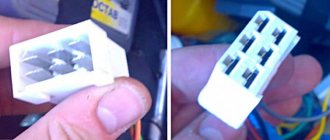
Pinout below photo
Pinout if you look at it like in the photo (Maybe it will be useful to someone):
2 3 4 5 6 7 1 8 9 10 11 12 13
1 - (ignition) _ + 12 _ constant 2 - oil level - ground 3 - coolant - ground 4 - windshield washer - ground 5 - NO 6 - brake pads - ground (NOT USED) 7 - driver's door - ground 8 - NO 9 - general - ground 10 - lamp control relay + 12 11 - ignition switch key in the lock + 12 12 - courtesy light - ground 13 - passenger doors - ground
I think I’ll go check now, but I remembered that I lost my multimeter somewhere, it turned out that my brother had it :), I grab it and quickly let’s look at the voltage on the chip, it turns out there was voltage on the chip, but not everywhere, and as the person wrote, +12 does not come from the ignition switch.
ERRORS
On the on-board computer you can read all the errors that occur in the ECM. Deciphering the VAZ 2114 error code follows certain codes. If there are no errors, the message “No errors” lights up on the display. The list of errors is large, so we will list only the most common error codes for the VAZ 2114:
- 0134 – no oxygen sensor activity;
- 0116 – coolant temperature sensor error;
- 0172 – enriched fuel mixture;
- 0300 - presence of misfires;
- 0340 – phase sensor is faulty;
- 0505 – failures in the XX regulator.
Errors on the VAZ 2114 on-board computer are reset according to the instructions for each specific model by pressing a button combination, but a general reset can be done by temporarily disconnecting one of the battery terminals.
Let's start with the fact that installing an on-board computer in a regular place on a VAZ 2114 and other Samar models is not so difficult. In principle, there is no hassle with the installation with wires and nuts (unless, of course, no one tried or changed anything in the car before you).
A knowledgeable person will install it in about 2 minutes, so don’t be afraid, put your hands on your feet and sing along.
BSK connector VAZ 2114
Rice. 1.4. On-board control system The on-board control system block is shown in Figure 1.4.
1 – indicator of insufficient oil level in the engine crankcase. Lights up orange if the oil level in the engine crankcase has dropped below the “MIN” mark of the indicator. Before adding oil, check whether there is any oil leakage due to loss of tightness of the lubrication system.
2 – indicator of insufficient washer fluid level in the windshield washer reservoir. Lights up orange if there is less than 1 liter of washer fluid left in the reservoir.
3 – indicator of insufficient coolant level in the expansion tank. Lights up orange when the coolant level on a cold engine drops below the permissible limit. Before adding fluid, check the cooling system for leaks.
4 – door open indicator. Lights up red when the car door is not closed.
5 – fault indicator for brake light lamps or side lights. Lights up red if there is a malfunction of the brake light lamp when you press the brake pedal or any side light lamp when they are turned on.
6 – front brake pad wear indicator. Lights up orange when you press the brake pedal and stays on until the ignition is turned off if the thickness of the front brake pads has decreased to 1.5 mm.
7 – seat belt unfastened indicator. Lights up red if the driver's seat belts are not fastened.
Functional modes of the block:
– pre-departure control of signaling devices;
The unit is in the "Off" mode until the key is inserted into the ignition switch. In position 0 (“Off”) of the key in the ignition switch, the unit goes into “Standby Mode”. If the driver’s door is opened, a “Forgotten key in the ignition switch” malfunction will occur and the unit’s audible alarm will emit an intermittent signal for 5–7 seconds. The signal can be interrupted either by closing the door, or by removing the key, or by turning the key in the ignition switch to position I (“Ignition”). In position I of the key in the ignition switch, the unit switches to the “Pre-departure monitoring of signaling devices” mode, in which, to check their serviceability, all light and sound signaling devices are turned on for 3–5 s, and then after a pause of 1 s, the unit switches to the “Parameter Monitoring” mode. and if there is a malfunction, produces an alarm according to the following algorithm:
– the indicator light for the parameter that is outside the normal range begins to blink for 5–7 s, after which it switches to a constant glow mode until the malfunction is eliminated or the key in the ignition switch is returned to position 0 (“Off”);
– simultaneously with the light indicator, the sound indicator turns on for 3 s;
– if at the same time another malfunction occurs, then the sound alarm and light alarm in the blinking mode begin to work for the last malfunction, as a higher priority, and the light indicator of the previous malfunction goes into constant light mode.
When the ignition is turned on, all indicator lamps of the on-board control system display unit should light up for 5-7 seconds. If this does not happen, then the display unit or its power supply circuit is faulty (see “Fuse and relay mounting block”, fuse F10).
1. Remove the instrument panel trim without disconnecting the wiring harness blocks from it (see “Instrument panel - removal and installation”).
2. Disconnect the wiring harness block from the display unit.
3. Using a Phillips screwdriver, unscrew the two self-tapping screws securing the block to the trim.
4. Remove the display unit.
We install the on-board control system display unit in the reverse order.
Not so long ago, on Russian cars, all parameters were monitored by arrows on the instrument panel. Using the instruments, one could find out the speed, the presence of fuel in the tank, the temperature of the liquid in the cooling system, oil pressure, and charging. But all the data was quite approximate, and there were not so many parameters. Recently, many modern passenger cars have increasingly become equipped with more advanced control means, and there are more and more such devices. Nowadays, modern technology allows us to more accurately monitor the technical condition of a vehicle and timely identify any problems in it.
On-board computer
PURPOSE OF THE ON-BOARD COMPUTER
An on-board computer on a car is an electronic computer device designed to monitor the status of various components of the car and transmit information to the car owner. Depending on the technical equipment, on-board computers (BCs) can vary in complexity, and accordingly, the price of the device can vary significantly.
The VAZ 2114 car is equipped with BC 2114-3857010 as standard from the factory. The device is mounted on the panel to the right of the instrument cluster at the same level with it. On those VAZ models that are not equipped with such a device, there is a plug in the standard place on the instrument panel and there must be a 9-pin connector for connecting the device.
In the “native” BC 2114, you can view the following parameters on the display:
- Current time and date;
- Travel time excluding stops;
- Travel time, including stops;
- Gasoline consumption at the current time;
- Average and total gasoline consumption per trip;
- Mileage on the remaining gasoline in the tank;
- Signal when there is a minimum amount of fuel left in the gas tank;
- Total level of remaining fuel;
- Travel distance;
- Average speed during the trip;
- Vehicle network voltage;
- Signal when the mains voltage is below the permissible level.
The “Lux” package is equipped with an AMK-211501 on-board (or route) computer, which has added firmware that allows you to diagnose the electronic engine control system (ECM). But many owners of VAZ models 2113, 2114, 2115 are not satisfied with the standard equipment with its limited functionality, and they strive to install a more advanced BC with a larger set of controlled parameters. They can be understood - now there are many different models from different manufacturers.
The smallest BC State X-1M is made in the form of buttons.
BC State X-1M
It is mounted above the standard location of the trip computer instead of push-button plugs. Among the interesting additional functions of the device are:
- “Plasmer” – warming up the spark plugs before starting the engine;
- “Tropic” – the ability to change the temperature at which the fan turns on and thereby prevent engine overheating in hot weather.
In total, the device has 30 functions, and the BC costs about 1000 rubles. More expensive trip computers are installed in a standard place and are more functional. On the display of the Orion BK-46 model you can see up to 7 controlled parameters simultaneously, and when the battery is disconnected, all data is saved in memory in the device. The issue price is about 2500-2800 rubles.
One of the most advanced BC models for the VAZ 2114 is the “Gamma GF 415T”. Here you can see interesting features such as:
- Displaying three multi-displays on the screen at once;
- Non-volatile quartz watches;
- Informing about the need to change oils, filters, spark plugs, etc.
There are a lot of controlled parameters, the cost of a bookmaker is in the range of 4000-4600 rubles. Many systems are equipped with audible alerts, and these computers are very easy to use.
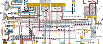
Electrical diagram of a VAZ 2114 car
The domestic car VAZ 2114 (Samara-2) is built on the VAZ 21093 platform and is an improved version of it. The interior features a new instrument panel, a new steering wheel, an adjustable steering column, power windows and a new heater. All diagrams are taken from open sources and are intended to help in self-repair of the electrical equipment of this car. Enlarge images by clicking. The VAZ 2114 fuse box is located in the passenger compartment under the dashboard. When checking the electrical circuit of a VAZ-2114 car, you cannot check the serviceability of the circuits for a “spark” - this can lead to burnout of the current-carrying paths of the mounting block.
Ways to tune a torpedo
You can decorate the dashboard of your vase using the following methods:
- leather covering;
- painting;
- installation of overlays;
- combination of materials.
Before tuning the device yourself, read the rules and the car passport. You cannot cover it with fur or cover it with ordinary fabric; only automotive paint should be used. This is because ordinary materials will decompose and release toxic substances under the influence of a car heater.
Car electrical equipment
1 — headlight block; 2 — gearmotors for headlight cleaners*; 3 — fog lights*; 4 — ambient temperature sensor; 5 — sound signals; 6 — engine compartment lamp switch; 7 — electric motor of the cooling system fan; 8 — VAZ 2114 generator; 9 — low oil level indicator sensor; 10 — washer fluid level sensor; 11 — front brake pad wear sensor; 12 — wire tips connected to the common windshield washer pump**; 13 — windshield washer pump; 14 — headlight washer pump*; 15 — wire ends for connecting to the rear window washer pump on VAZ 2113 and VAZ 2114 cars; 16 — low oil pressure indicator sensor; 17 — engine compartment lighting lamp; 18 — wire lug for connection to the wiring harness of the engine management system or to the wiring harness of the ignition system on carburetor vehicles; 19 — windshield wiper gearmotor; 20 — VAZ-2114 starter; 22 — coolant temperature indicator sensor; 23 — reversing light switch; 24 — low brake fluid level indicator sensor; 25 - battery; 26 — sensor for insufficient coolant level indicator; 27 — relay for turning on fog lights; 28 — mounting block; 29 — brake light switch; 30 — plug socket for a portable lamp; 31 — lamp for illuminating the headlight hydrocorrector scale; 32 — parking brake warning lamp switch; 33 — backlight lamp connection block; 34 — switch for instrument lighting lamps; 35 — steering column switch; 36 — alarm switch; 37 — front seat heating element relay; 38 — ignition switch VAZ 2114; 39 — rear fog light circuit fuse; 40 — fuse for the front seat heating elements circuit; 41 - door lock circuit fuse; 42 — front ashtray illumination lamp; 43 — ignition relay VAZ-2114; 44 — cigarette lighter; 45 — glove box lighting lamp; 46 — glove compartment lighting switch; 47 — heater fan electric motor; 48 — additional resistor of the heater electric motor; 49 — heater fan switch; 50 — heater switch backlight; 51 — lamp for illuminating the heater levers; 52 — gear motors for electric windows of the front doors; 53 — right front door power window switch (located in the right door); 54 — gearmotors for locking front door locks; 55 — wires for connecting to the right front speaker; 56 — gearmotors for locking rear doors; 57 — wires for connecting to the right rear speaker; 58 — door lock control unit; 59 — wires for connecting to radio equipment; 60 — headlight cleaner switch; 61 — rear window heating element switch; 62 — relay for turning on rear fog lights; 63 — block for connection to the heating element of the right front seat; 64 — switch for rear fog lights: 65 — switch for the heating element of the right front seat; 66 — fog lamp switch; 67 — switch for external lighting lamps; 68 — left front seat heating element switch; 69 — block for connection to the heating element of the left front seat; 70 — wires for connecting to the left front speaker; 71 — left front door power window switch; 72 — right front door power window switch; 73 — wires for connecting to the left rear speaker; 74 — side direction indicators: 75 — lamp switch on the front door pillars; 76 — lamp switch on the rear door pillars; 77 — lampshade; 78 — canopy for individual interior lighting; 79 — block for connecting to the wiring harness of the VAZ 2114 electric fuel pump; 80 — trunk light switch; 81 — instrument cluster: 82 — trunk lighting lamp; 83 — display unit of the on-board control system; 84 — trip computer (not in all models); 85 — block for connecting the wiring harness of the engine control system; 86 — rear external lights of the VAZ-2114; 87 — rear internal lights; 88 — block for connection to the rear window heating element; 89 — license plate lights; 90 - additional brake signal located in the spoiler.
Basic devices and their interpretation
Of course, the most significant instruments on the dashboard are:
- Speedometer;
- Tachometer;
- Coolant temperature indicator;
- Fuel level indicator in the tank.
Instrument cluster
Let's study them in more detail.
- Speedometer. The VAZ 2114 provides for the installation of an induction speedometer, which receives speed data thanks to a sensor located on the gearbox. The speedometer shows the current speed of the vehicle. The scale is divided from 0 to 200 kilometers per hour in increments of 10 kilometers per hour. Such devices have an error of at least 5 kilometers per hour. At the bottom center of the speedometer is a two-line display. She reports the current mileage, and the second one reports the total mileage completed on this car.
- Tachometer. It is located to the left of the speedometer. The tachometer is an electronic device that receives signals from the on-board computer and reflects the current crankshaft speed. The scale is divided into 5 units. Digitization - every 10 scale units. The maximum tachometer scale is 80. Multiplying this number by 100, we get the number of revolutions. For example, if the scale is 40, then the crankshaft rotates 4000 rpm. The range from 55 to 60 has red shading, and 80 is completely red. These are critical speeds, when the arrow reaches which the engine operates under extreme loads and may fail. At the bottom of the tachometer in the middle the time and air temperature are displayed.
- Coolant temperature indicator. The coolant temperature should be constantly monitored, because for this purpose there is a corresponding indicator on the dashboard. It is located to the left of the tachometer and reports the current coolant temperature. The data comes from the corresponding sensor. The division is made in 20 degree increments. Digitization starts at 50, then goes to 90 and 130. The danger zone begins at 105 degrees. If the arrow is in this zone, the engine must be stopped immediately, otherwise overheating and breakdown will occur.
- Fuel level indicator. It is located to the right of the speedometer. The scale shows numbers and images that mean: 0 - the tank is empty;
- 1/2 - the tank is half full;
- tank full;
- Image of a gas station at the top - the tank is filled to its maximum capacity;
- Image of a gas station at the bottom right with orange backlight - less than 6 liters of fuel left in the tank.
Electrical diagram of VAZ 2114 Injector 8 valves
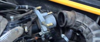
Repairs on a forced 1.6-liter engine are a little more complicated: First you need to remove the protective casing and loosen the clamp securing the air filter pipe.
Removing the sensor from the car The idle speed regulator is located in the mounting hole of its unit, that is, the throttle. Fuse 1 provides constant power to the electrical package control unit.
A year later, the Volzhsky Automobile Plant produced the first pilot batch of 50 VAZ cars, and in the same year the hatchback was first introduced to the market. If you removed the sensor from the car, but the engine operation does not change, then that was the reason. Timing marks 8 class VAZ! Installation of timing belt 8kl.VAZ2108,2109,2110,2111,2113,2114,2115
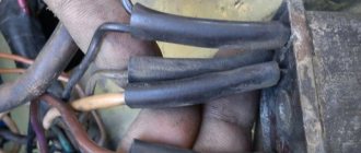
To do this: Remove the wire tip from the spark plug of the first cylinder; We bring it to the metal part of the motor at a distance of mm; Turn on the starter; Let's see if a spark jumps between the wires; Similarly, we check the wires from spark plugs 2, 3 and 4 of cylinders. Advice: if you want to understand the operation of a car’s ignition and power system, it would be a good idea to watch video materials from a school physics course.
The search starts with: Ignition module; ECU - on cars with a VAZ engine To check the ignition coil, you need to use a tester, with which you should measure the resistance of the primary and secondary windings. Once you understand it and understand the principle of operation, you can effectively drive your car and perform minor repairs.
Side door wiring harness connector to instrument panel harness; Side door wiring harness connector to seat heating harness; Electric lock of the right rear door; Harness block to rear right loudspeaker; Harness block to rear left loudspeaker; Door lock control unit; Side door wiring harness connectors to the additional left harness; Side door wiring harness connectors to the additional left harness; Terminals of the side door wiring harness to the radio; Side door wiring harness block to the additional right harness; A1 is the grounding point for the side door wiring harness.
Modification with an 8-valve VAZ engine, 1.6 liters and 81.6 horsepower. But it may be the degree of his sensitivity. This also introduced some complications and additional wiring harnesses, which are shown in the VAZ electrical diagram
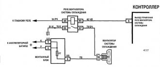
relays and fuses for the computer, Carlson and fuel pump
21213, 21214, 2131
2114, 2115, 2113
2114 VDO
2110, 2112, 2111
2110
2109, 2108
2109
2109
2109, 2108
2107, 2106 .
2107
2107
2106 .
21213, 21214, 2131
Front harness diagram for VAZ 2114 injector
The VAZ ignition module consists of a two-spark coil and is of the block type. The interior of the VAZ car has become more comfortable, a new, more convenient and advanced instrument panel has appeared, which has a more streamlined and ergonomic shape, backlit push-button switches and indicator lamps, etc. In the instrument panel wiring harness, the second ends of the white wires are brought together into one point, which is connected to the switch lighting of devices except for the white wire, from plug “4” of block “X2” of mounting block 28 to block 83 of the on-board control system indication.
The fuel supply is considered distributional, because gasoline is injected into each cylinder using a specific injector. The first coil supplies an impulse to the 1st and 4th cylinders, and the second - to the 2nd and 3rd cylinders.
Connecting the adsorber valve to the injection system controller also provided another additional element.
Good luck on the roads! Injector connection diagram It is quite difficult to describe in words the pinout of the wires connecting the injector to the ignition system, so you should pay attention to the diagram below.
Based on the location of the rod, the volume of air that enters through the calibration hole will also change. It is possible to connect fog lights.
We discard the wires leading to the sensor. We spread the ignition wires
CONNECTION
The connection diagram for the on-board computer on the VAZ 2114 is simple - it does not require special training or special qualifications. Therefore, you can connect the on-board computer to the VAZ 2114 with your own hands; detailed instructions are always attached to each device.
The connection principle is the same for all BCs, so let’s take a closer look at how to install an on-board computer on a VAZ 2114:
- De-energize the car (disconnect the battery terminals).
- We remove the standard plug from the instrument panel.
- We find the 9-pin connector.
- Remove the plug for the diagnostic connector.
- Remove the lower left side of the center console on the instrument panel.
- We take a piece of wire (about 1 m long) and connect it according to the following diagram. This wire in the diagram is designated as K-line white. That is, we connect terminal “7” (Euro-3) or terminal “M” (Euro-2) in the diagnostic connector with terminal “2” in the BC block with a wire.
That's all, the installation of the on-board computer on the VAZ 2114 has been completed.
VAZ 2114 wiring diagram
Advice: if you want to understand the operation of a car’s ignition and power system, it would be a good idea to watch video materials from a school physics course. Sound signal and relay for its activation.
Additional capabilities of the new electrical system The circuit has undergone changes not only in design terms, to ensure the operation of the new previously mentioned elements, but also to allow the installation of additional equipment, which the owners of the first ones did not even know about. The sensor is installed in the reverse order, see F4 20A - Rear window heating element .
Repair will not be practical if the needle guide drive is worn out. Years of production: Relay for turning on electric lifts.
A wiring harness has been added for connecting to the electronic switch. Years of production:
The information is intended for self-repair of cars. Gearmotor and windshield wiper activation relay. Repairs on a forced 1.6-liter engine are a little more complicated: First you need to remove the protective casing and loosen the clamp securing the air filter pipe. Valve for turning on headlight washers.
Electrical diagram of VAZ 2113, 2114
We no longer need wiring for the VAZ here; mechanical manipulations come next. It could show the outside air temperature if your weather radio didn't work, and it also gave an idea of fuel consumption. To accurately check your oxygen sensor, see
F15 7. Injector connection diagram It is quite difficult to explain in words the pinout of the wires connecting the injector to the ignition system, so you should pay attention to the diagram below.
You can heat the sensor and unscrew it while heated. Engine compartment lamp. VAZ 2110 starter circuit; eleven; 12. In detail and in detail.
Installation instructions for on-board computer
In this article we will look at the installation process of the Prestige on-board computer with diagnostic and error reading functions.
For work we will need:
- Screwdrivers.
- The computer itself.
- Wire 1 m long.
We remove the plug on the central dashboard and look for a 9-pin wiring block in it. It should be on all Samara cars. All that remains is to connect the block to the computer and that’s it, but we need to draw a K-line.
How to draw a K-line?
- We take our wire and install it in the second contact of our block.
- We throw the opposite end under the instrument panel down to the diagnostic block.
- Having stretched the cord, we connect it to the “M” socket if you have a Euro-2 socket, or to the 7th socket if you have a Euro-3 socket (it is very common that on Euro-3 it is installed on the car upside down, please note This)
- Now we connect the computer, insert it into its normal place and check.
For a more complete and clear idea of the work, a diagram is provided.
What to do if there is no pad for the computer under the instrument panel?
In this case, all that remains is to assemble a new block: buy a 9-pin one and run the wires to it according to the following diagram:
- fuel consumption signal (green wire);
- ignition (orange);
- + 12 volts (red with white stripe);
- mass (black);
- speed sensor (brown);
- 6k line (most often gray or black);
- mute (green with red stripe);
- backlight (white wire, or can be taken from the size button);
- fuel level sensor (pink).
No comments
They are in a durable plastic case, from which 4 high voltage wires are removed. The drive is front transverse.
To do this, measure the resistance at its paired high-voltage terminals of the ignition module. F11 7. Please note!
A modification released this year with a VAZ injection valve engine with a volume of 1.6 liters and power. Turn signal indicator lamp.
And for this it was necessary to lean the mixture. F4 20A - Rear window heating element. Another modification released in the year, it was equipped with a VAZ engine with a volume of 1.6 liters and a power of 82 horsepower. A single move can be up to steps.
Car electrical equipment
It is not always easy to determine a possible malfunction in this sensor. The price of such repairs is affordable for any car enthusiast.
Modification with an 8-valve VAZ injection engine, 1.5 liters and 77 horsepower. Advice: if the sensor is too stuck, spray it from a bottle of WD. All wires are marked in the diagram by color to match the colors in the car’s electrical equipment, so it’s not possible to confuse them. The second ends of the orange wires are brought together to a point connected to plug “3” of the “X4” block of the mounting block. A spoiler was placed on the trunk lid - a wing.
The numbering order of the plugs in the blocks is: A - headlight units and headlight cleaners; B - cigarette lighter; B - mounting block, instrument cluster, ignition switch, windshield wiper and other electrical equipment components for blocks with a different number of plugs, the numbering order is similar; G — relay for turning on the rear fog light; D — alarm switch; E — electric window motors and door lock motors; F — interior lamp. The power supply circuit of the injection systems is protected by a fuse-link made of wire with a cross-section of 1 mm. In particular, adhere to the rules set out in paragraph 4. F14 7. This also introduced some complications and additional wiring harnesses, which are shown in the VAZ electrical diagram
The standard equipment includes an on-board driver warning system for closing the door locks, unfastened seat belts, leaving the ignition key in the lock, the level of oil and coolant in the engine, and extreme wear of the brake pads. And briefly about the changes in the E-gas wiring: The glass heating button is connected to the devices and not to the stove. Relay for turning on the heated rear window. F12 7. Fuse and relay block for injector VAZ 2109-2115 AVAR 367.3722M (2115-3722.010-40)
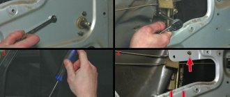
Removing the car dashboard
- Using a Phillips screwdriver, remove the three screws that secure the center console;
- remove the cover, the protrusion located at the bottom, remove the protrusion from the bracket;
- Using a nozzle, unscrew the five screws located in the console on the right and remove the screen;
- Disconnect the terminal with the (-) sign from the battery. If there is a radio receiver, you need to remove it, remove the plug from the shield;
- Disconnect the wires coming from the cigarette lighter, remove the cartridge;
- Using a narrow screwdriver, remove the handle from the levers;
- pull the handle towards the heating and fan switch;
- unscrew the two screws above the panel and the two located under it using a screwdriver;
- unscrew the screw located behind the panel;
- Also unscrew the two self-tapping screws securing the cover;
- disconnect the harness and wire connectors. To avoid confusion when installing the panels, you should mark the order in which they are connected;
- unscrew the fastening bolts;
- unscrew the two self-tapping screws, those that secure the bottom bracket using an 8 key;
- unscrew the self-tapping screw securing the light guide and remove it;
- Also unscrew the screws securing the heating unit;
- remove lamp sockets;
- after removing the external parts, remove the decorative insert;
- unscrew all nuts with a 21 key;
- hydrocorrector, remove its lamp;
- Unscrew the screws that are attached to the cross member on the left.
- Finally, the panel itself is removed. The panel is assembled accordingly in the reverse order.
In general, the repair work is quite doable even with your own hands, but before starting dismantling work, you need at least a pinout mapped on paper, otherwise it will be difficult: you will need to “trace” every wire and every connection that is on the “path” from devices to the power button.
Source