Electric windows in modern cars are no longer a rare system that many can only dream of. Even AvtoVAZ installs this system from the factory on new models. But any mechanism has wear and tear, which is why from time to time you need to know the pinout of the VAZ 2114 window lifter button, the complete system diagram, etc. Car owners are used to repairing cars themselves, and despite the fact that the mechanisms change, they still try to study them and get rid of faults on their own.
Video: How to connect power windows yourself easily and quickly:
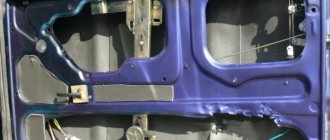
How to disassemble a side mirror
Sometimes a complete replacement of the side view mirror of a VAZ-2114 is required. It is quite possible that everything can be done by installing a separate element on the left or right side.
Let's see how we can disassemble the structure as carefully as possible. First you need to press the plastic case from the inside. The holders are carefully snapped off using a flat-head screwdriver. This method is not very reliable - there is a considerable chance that the mirror element or other parts will break.
The second option carries even greater risks - here you need to quickly hit the glass on the surface (but it is better if it is soft). This is a quick option for dismantling and replacing the element. The blow should be light and fast. To replace the plastic housing or main fastener, remove the adjusting rods and pin. The assembly is done exactly the opposite.
Types of window lifters
Automobile manufacturers produce cars of different configurations. The cheapest ones have manual windows. They create fewer electrical problems, but the inconvenience of using them is that while in the driver's seat, it is impossible to open the window on the passenger side without being distracted from driving.
Manual window lifters, which are installed on the conveyor, have slight differences from electric ones. The mechanism itself that lifts the glass is exactly the same.
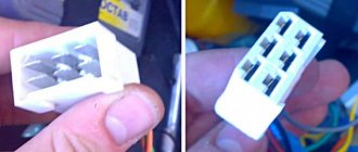
The difference is that the manual version has a gearbox that transmits the rotation of the window handle to the window lifting device, while in the electric version this function is performed by an electric motor. On the door trim, in place of the hole for the manual drive, there is a plug. In addition, the electrical wiring has an additional connection diagram for VAZ-2114 window regulators.
Heater design and circuit
Structurally, the rear window heater is presented in the form of conductive strips through which current flows. This current causes these strips to heat up, resulting in heating of the entire glass, which means defrosting the ice and eliminating fogging.
The heating circuit includes not only conductive strips, but also relays, wiring and a fuse. To turn on the device, a button is installed in the interior of the VAZ 2107 car. To understand how the design of this device works, below is a diagram that shows in detail all the components.
In the diagram, each element has its own purpose:
- A mounting block or relay and fuse block is a device that houses a relay with two fuses inside.
- Relay - helps to reduce the current in the circuit, thereby eliminating overheating of the wiring and failure of the power button.
- Ignition switch - a positive contact comes from the lock, which eliminates the possibility of turning on the rear window heater when the engine is not running.
- The button is dual-mode - turns the device on and off.
- The warning light is an indicator indicating the operation of the system and is located on the dashboard.
- Heater - has the form of conductive strips or threads that are glued to the glass on the inside.
Knowing the circuit diagram of the device, it will not be difficult to eliminate various malfunctions. We will consider below what types of malfunctions most often occur in the rear window heating system of the VAZ 2107.
For what reasons does the heating not work?
Owners of sevens know all the “sores” of this domestic vehicle, so when a malfunction occurs with the rear window heater, you don’t have to look for a breakdown for long. However, beginners and those who have not yet encountered such a malfunction are wondering how to check the system to find the cause and the faulty part.
The following reasons are identified for the inoperability of the heated rear window of the VAZ 2107:
- The fuse is faulty - if, when you turn on the rear window heating button, you find that it does not light up, then the first thing you need to check is the serviceability of fuse F7. It is he who most often burns out, which leads to the inoperability of the system. The reasons for its burnout are known - the passage of a large amount of current.
- Malfunction of the rear window heating relay - the relay, the main purpose of which is to reduce the current supplied to the power button, can also fail. If it malfunctions, it will need to be replaced.
- Malfunction of the power button - the reason for its failure is oxidation or carbon deposits on the contacts that occur when turned on. After all, it is known that when the rear window heating is turned on, a current is generated whose value is ten times the nominal value. This phenomenon contributes to the formation of carbon deposits on the button contacts.
- Damage to conductive threads. The cause of their malfunction is a broken contact. However, any breakdown in the system can be eliminated if the cause and location of the damage are correctly identified.
So, if a fuse, relay or button fails, then these parts cannot be repaired and must be replaced. Damage to wiring is extremely rare, so it can only be called when all of the above elements have been checked.
Heating restoration
The reasons for the rear window heater not working on the VAZ 2107 are known, but many do not know why the conductive strip may break. The reason is somewhat trivial - too zealous washing of the glass surface or incorrect application of the tint film. Even if this happens, you should not despair, because you can always repair the heated rear window of a VAZ 2107.
First you need to find the location of the damage, as sometimes this is very difficult to do. If the location of the damage is visually traced, then such damage can be eliminated using a special “Kontaktol” repair kit from Keller or analogues. Its cost is about 400-600 rubles, and you can find it in any auto store.
Replacing the window regulator
If the VAZ-2114 window regulator does not work, it can be replaced with a new one. To do this you need to do the following:
- Using a 10 mm wrench, unscrew the three nuts that hold the glass guide.
- Using a size 8 wrench, unscrew the three nuts that secure the electric motor or manual drive gearbox.
- Disconnect the glass mounting bracket from the glass holder. To do this, you need to unscrew the two 8mm bolts on the bracket.
After this, you can pull the window regulator out of the door. The glass must remain raised. Otherwise it will be impossible to remove the mechanism.
The new lift is installed in the reverse order. However, there is no need to rush to tighten the glass mounting bracket. First you need to make sure that the glass is in the correct position in the guides and moves clearly in them.
Shendys › Blog › Mounting block 2110
| Relay no. | vendor code | Purpose |
| K1 | lamp health monitoring relay | |
| K2 | windshield wiper relay | |
| K3 | relay-interrupter for direction indicators and hazard warning lights | |
| K4 | low beam headlight relay | |
| K5 | headlight high beam relay | |
| K6 | additional relay | |
| K7 | rear window heating relay | |
| K8 | backup relay (not installed on VAZ-2110 family vehicles) |
Circuit breakers
| No. prev. | Ampere | Purpose |
| F1 | 5 A | Lighting lamps: license plates, instruments, dimensions on the dashboard, left dimensions, trunk lighting |
| F2 | 7.5 A | Low beam in the left headlight |
| F3 | 10 A | High beam in the left headlight |
| F4 | 10 A | Right front fog lamp |
| F5 | 30 A | Door windows |
| F6 | 15 A | Portable lamp, cigarette lighter |
| F7 | 20 A | Radiator fan, horn |
| F8 | 20 A | Heated rear window |
| F9 | 20 A | Windshield washer and cleaner |
| F10 | 20 A | Reserve |
| F11 | 5 A | Dimension on the right side |
| F12 | 7.5 A | Low beam in the right headlight |
| F13 | 10 A | High beam in the right headlight |
| F14 | 10 A | Fog lamp, left |
| F15 | 20 A | Seat heating |
| F16 | 10 A | Hazard signal, turn signals |
| F17 | 7.5 A | Brake light, ignition switch illumination, interior lighting |
| F18 | 25 A | Cigarette lighter, glove compartment light, interior heater |
| F19 | 10 A | Reversing lamp, brake light monitoring |
| F20 | 7.5 A | Rear fog lights |
Additional fuse diagram
Main characteristics
The VAZ 21099 “Berkut” window regulator is equipped with a metal mechanism with articulated levers. This design allows you to raise the windows both on the VAZ 21099 and on other domestic and European brands of cars. It should be noted that such a mechanism is equipped with a modern geared motor PT-060. Its assembly is carried out in Izhevsk using new Swiss technology. These electric windows are equipped with:
- wiring numbered according to the electrical diagram;
- switch buttons;
- decorative plugs;
- additional fasteners;
- rubber transition cuffs.
Car electrical equipment
1 — headlight block; 2 — gearmotors for headlight cleaners*; 3 — fog lights*; 4 — ambient temperature sensor; 5 — sound signals; 6 — engine compartment lamp switch; 7 — electric motor of the cooling system fan; 8 — VAZ 2114 generator; 9 — low oil level indicator sensor; 10 — washer fluid level sensor; 11 — front brake pad wear sensor; 12 — wire tips connected to the common windshield washer pump**; 13 — windshield washer pump; 14 — headlight washer pump*; 15 — wire ends for connecting to the rear window washer pump on VAZ 2113 and VAZ 2114 cars; 16 — low oil pressure indicator sensor; 17 — engine compartment lighting lamp; 18 — wire lug for connection to the wiring harness of the engine management system or to the wiring harness of the ignition system on carburetor vehicles; 19 — windshield wiper gearmotor; 20 — VAZ-2114 starter; 22 — coolant temperature indicator sensor; 23 — reversing light switch; 24 — low brake fluid level indicator sensor; 25 - battery; 26 — sensor for insufficient coolant level indicator; 27 — relay for turning on fog lights; 28 — mounting block; 29 — brake light switch; 30 — plug socket for a portable lamp; 31 — lamp for illuminating the headlight hydrocorrector scale; 32 — parking brake warning lamp switch; 33 — backlight lamp connection block; 34 — switch for instrument lighting lamps; 35 — steering column switch; 36 — alarm switch; 37 — front seat heating element relay; 38 — ignition switch VAZ 2114; 39 — rear fog light circuit fuse; 40 — fuse for the front seat heating elements circuit; 41 - door lock circuit fuse; 42 — front ashtray illumination lamp; 43 — ignition relay VAZ-2114; 44 — cigarette lighter; 45 — glove box lighting lamp; 46 — glove compartment lighting switch; 47 — heater fan electric motor; 48 — additional resistor of the heater electric motor; 49 — heater fan switch; 50 — heater switch backlight; 51 — lamp for illuminating the heater levers; 52 — gear motors for electric windows of the front doors; 53 — right front door power window switch (located in the right door); 54 — gearmotors for locking front door locks; 55 — wires for connecting to the right front speaker; 56 — gearmotors for locking rear doors; 57 — wires for connecting to the right rear speaker; 58 — door lock control unit; 59 — wires for connecting to radio equipment; 60 — headlight cleaner switch; 61 — rear window heating element switch; 62 — relay for turning on rear fog lights; 63 — block for connection to the heating element of the right front seat; 64 — switch for rear fog lights: 65 — switch for the heating element of the right front seat; 66 — fog lamp switch; 67 — switch for external lighting lamps; 68 — left front seat heating element switch; 69 — block for connection to the heating element of the left front seat; 70 — wires for connecting to the left front speaker; 71 — left front door power window switch; 72 — right front door power window switch; 73 — wires for connecting to the left rear speaker; 74 — side direction indicators: 75 — lamp switch on the front door pillars; 76 — lamp switch on the rear door pillars; 77 — lampshade; 78 — canopy for individual interior lighting; 79 — block for connecting to the wiring harness of the VAZ 2114 electric fuel pump; 80 — trunk light switch; 81 — instrument cluster: 82 — trunk lighting lamp; 83 — display unit of the on-board control system; 84 — trip computer (not in all models); 85 — block for connecting the wiring harness of the engine control system; 86 — rear external lights of the VAZ-2114; 87 — rear internal lights; 88 — block for connection to the rear window heating element; 89 — license plate lights; 90 - additional brake signal located in the spoiler.
The final stage
Installation of electrical control system
The lever system is moved to a convenient position for fixing the glass. The mechanism is then connected to the adjustment plate and glass. The nuts are tightened. You can move the lever system to a position convenient for fixing the glass if you use an alternative power source. It is better to give preference to a double wire and a standard car battery.
It is possible to decide how to connect the power windows on a VAZ 21099 using the wiring diagram for the “nine”. In any case, the functionality of the mechanism in question is checked using the method described above. When the glass comes out of the grooves of the guides, you will need to loosen the nuts that secure the adjusting plate.
The short guide is then secured into the top hole. If the glass moves with a certain force, a cutoff occurs. In this situation, the nuts that secure the plate are loosened. To do this, attach a short guide to the hole below.
When moving glass from the lower extreme position to the upper one, you must take into account that it should not come out of the guide grooves. A similar procedure is carried out 2-3 times.
Then the fastener is fixed. The process related to how to connect a window regulator to a used VAZ 21099 involves the use of silicone spray. In this case, the glass will fit into the seals without problems.
You have a "nine". During the production of this model, the plant did not install an electric window - with rare exceptions. This publication discusses in detail the installation of electric windows on the VAZ 2109. As for which ones to take, experienced car enthusiasts are inclined to favor the products and “Granat”.
There are three types of similar parts:
- cable
- the cheapest option, therefore the worst (the windows rise and fall slowly, if the glass freezes, the cable may break and the drive will fail) - rack and pinion
- can also break if the glass freezes; you also need to constantly lubricate the mechanism so that it does not jam; - hinged-lever
- the most expensive option, but also the most optimal, because the glass moves quickly, does not make noise during operation, and will not break, even if the glass is frozen.
Also choose window regulators, the kit of which, in addition to the electric motor, also includes: wiring, buttons, a plug, the necessary fasteners and rubber cuffs. The latter will come in handy when you run wiring from the rack into the door.
Now let's get to the main topic of our story...
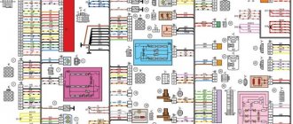
Diagram of the VAZ engine management system with BOSCH controller - ECM 21104 1.6 16V
1 – block of the ignition coil wiring harness to the ignition system harness; 2 – block of the ignition system harness to the ignition coil wiring harness; 3 – ignition coils; 4 – immobilizer warning sensor; 5 – immobilizer control unit; 6 – spark plugs; 7 – nozzles; 8 – diagnostic block; 9 – block of the ignition system harness to the ABS cabin group harness; 10 – controller; 11 – electric fuel pump; 12 – block of the ignition system harness to the fuel level sensor harness; 13 – fuel level sensor harness connector to the ignition system harness; 14 – block of the ignition system harness to the injector harness; 15 – injector harness block to the ignition system harness; 16 – block of the ignition system harness to the side door harness; 17 – speed sensor; 18 – idle speed regulator; 19 – throttle position sensor; 20 – coolant temperature sensor; 21 – mass air flow sensor; 22 – oil pressure warning lamp sensor; 23 – phase sensor; 24 – oxygen sensor; 25 – crankshaft position sensor; 26 — knock sensor; 27 – solenoid valve for purge of the adsorber; 28 – oil level sensor; 29 – coolant temperature indicator sensor; 30 – block of the ignition system harness to the instrument panel harness; 31 – instrument panel harness connector to the ignition system harness; 32 – ignition relay; 33 – ignition relay fuse; 34 – fuse for the electric fuel pump power supply circuit; 35 – electric fuel pump relay; 36 – electric fan relay; 37 – controller power supply fuse; 38 – ignition system harness block to the air conditioner connector; 39 – instrument cluster; 40 – ignition switch; 41 – electric fan of the cooling system; 42 – on-board control system unit; 43 – starter relay; 44 – contacts of the 8-terminal blocks of the instrument panel harness and the front harness; 45 – contacts of the 21-terminal blocks of the instrument panel harness and the rear harness; 46 – trip computer; 47 – diagnostic connector.
To watch online, click on the video ⤵
Lada Vesta 2022 / How to remove the power window control unit from the left door Read more
How to remove the passenger door trim on a Lada Granta Read more
How to properly remove the Grant door trim Read more
Removing the driver's door trim of the Lada Granta More details
Repair of the Lada Kalina window lifter button More details
Removing the rear door trim of Lada Granta, Kalina More details
Assembling and disassembling window switch 11180-3709613-00 More details
LaGranta - ESP switch block (1 part) More details
Lada Granta — Removing the rear right door trim More details
Replacing the driver's door module while retaining the original keys of the Lada Priora Kalina Granta More details
ESP control button from Lada Kalina/Granta on Nexia More details
Lada Granta - sound insulation of rear doors. More details
Replacing the outer door handle on Kalina and Grant Read more
Vibration isolation with one sheet of rear doors, installation of acoustics on Grant. More details
Kalina When door handles dangle. Body repair. More details
20 PRODUCTS FOR LADA GRANT FROM CHINA WITH ALIEXPRESS COMPETITION Read more
Lada Granta - installing speakers in the rear doors. More details
Lada Granta - eliminating rattling side windows. More details
VAZ. Easy removal of the window lifter handle. More details
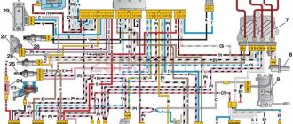
Wiring diagram VAZ 2114 injector - mounting block
Wiring diagram of the mounting block VAZ 2114 injector 8 valves with a full description
K1 - relay for turning on headlight cleaners; K2 - relay-interrupter for direction indicators and hazard warning lights; K3 - windshield wiper relay; K4 - lamp health monitoring relay; K5 - power window relay; K6 - relay for turning on sound signals; K7 — relay for turning on the electric heating of the rear window; K8 - headlight high beam relay; K9 - relay for low beam headlights; F1-F20 - fuses; X11 - terminals of the wiring harness block. The power supply circuit of the injection systems is protected by a fuse-link made of wire with a cross-section of 1 mm. Powerful consumers (starter, headlights) are connected to the VAZ 2114 injector wiring diagram via a relay.
F1 (10A) - Headlight cleaners. Relay for turning on headlight cleaners (contacts). Valve for turning on headlight washers.
F2 (10A) - Direction indicators and hazard warning relay-breaker. Hazard warning lamp.
F3 (10A) - Rear lights (brake lamps). Interior lighting.
F4 (20A) - Rear window heating element. Relay for turning on the heated rear window. Socket for portable lamp.е
F5 (20A) - Electric motor of the engine cooling system fan and switching relay (contacts). Sound signal and relay for its activation.
F6 (30A) - Power windows for front doors. Relay for turning on electric lifts.
F7 (30A) - Headlight cleaners (in operating mode). Relay for turning on headlight cleaners (winding). Heater fan motor. Window washer motor. Rear window wiper motor. Rear window washer timing relay.
F8 (7.5A) - Left fog lamp.
F9 (7.5A) - Right fog lamp.
F10 (7.5A) - Left headlight (side light). Left rear light (side light). License plate lights. Engine compartment lamp. Instrument lighting lamps. Indicator lamp for external lighting. Heater lever illumination display.
F11 (7.5A) - Right headlight (side light). Right rear light.
F12 (7.5A) - Right headlight (low beam).
F13 (7.5A) - Left headlight (low beam).
F14 (7.5A) - Left headlight (high beam). Indicator lamp for turning on the high beam headlights.
F15 (7.5A) - Right headlight (high beam).
F16 (15A) - Direction indicators and relay-breaker for direction indicators and hazard warning lights (in turn indication mode). Turn signal indicator lamp. Rear lights (reversing lamp). Gearmotor and windshield wiper activation relay. Generator excitation winding (when starting the engine). Oil pressure warning lamp. Air damper control. Coolant temperature gauge.
The VAZ dashboard has an electronic combination, as well as conveniently located backlighting. The lamps are illuminated from the inside, which is a feature of the 14th Lada.
Thanks to the instrument panel, the driver knows all the information he needs, what is the reserve and consumption of gasoline, mileage, etc. The panel should be easy to operate with a clear overview of the icons, scale, gauge and indicators.
What is the state of the automobile systems responsible for road safety, driving speed, the rest of the way to the intended object, rational engine operation and gasoline consumption, the operation of the suspension and electrical equipment - all this should be reflected on the control panel.
Signal lamps and equipment control devices must be required on the panel. There are a total of 19 symbols on the panel.
Rack and pinion window lift
Another good option for replacing standard mechanisms is rack and pinion windows. They are produced and have proven themselves well. These devices are characterized by high lifting and lowering speeds. Just as in the case of lever mechanisms, they have more force than standard ones. Despite the more modest dimensions of the electric motor, which is connected by standard connectors of the VAZ-2114 power window connection diagram.
The secret to the reliability of the device is the simple kinematic diagram of the transformation of the rotation of the electric motor shaft into the translational movement of the glass mounting bracket. There is a gear on the motor shaft that meshes with the teeth of the rack. This allowed additional parts to be kept to a minimum and simplified the design. And in combination with high-quality manufacturing materials, it ensured reliable operation.
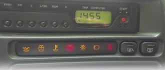
The dashboard diagram (Fig. 1.1) includes controls:
1 – lever-switch for headlight or turn signal modes.
2 – nozzle for blowing the front door glass.
3 – instrument cluster.
4 – steering wheel.
5 – button to turn off sound signals.
6 – button to turn off the alarm. Pressing the button causes the warning light and direction indicators to flash.
Photo 1. Hazard switch off button
7 – ignition switch combined with an anti-theft device. Never turn off the ignition or remove the key from the lock while driving, otherwise the steering will be blocked and the vehicle will lose control. The ignition key can have three positions:
- 0 – “disabled”. Consumers are disconnected, the key can be easily removed. When the key is removed, the closing mechanism of the anti-theft system is activated. To guarantee the steering shaft block, turn the steering wheel left or right until it clicks. To turn off the anti-theft device, you need to insert the key into the ignition and, turning the steering wheel left and right, turn the key to position “I”;
- I – “ignition”. The ignition is on, the key is not removed, the steering is unlocked;
- II – “starter”. The key cannot be removed, the steering is unlocked. The position is achieved by turning the key to overcome the elastic force of the spring. The key is not locked in this position; it must be held by hand for the starter to operate. The ignition switch is also equipped with a starter activation unit while the engine is running.
To repeat turning on the starter after a failed start attempt, you need to move the ignition key from position “I” to position “0”, and then again to position “II”.
8 – switch lever for windshield washer and windshield wipers.
9 – immobilizer sensor, transmits a special code from the code key through the immobilizer to the engine control unit.
10 – set of signal lights for the on-board control system. The complex contains (Fig. 1.2): 1 – oil level drop signal; 2 – low level signal in the windshield washer tank; 3 – low coolant level signal; 4 – door open signal; 5 – signal of malfunction of the brake light and side lights; 6 – signal of wear of the linings on the brake pads; 7 – the signal indicates that the seat belts are not fastened.
11 – external lighting switch.
12 – block of keys for turning off fog lights, fog lights, heated rear window.
13 – trip computer, installed on some vehicles, designed to display one of the parameters: current fuel consumption (or average total fuel consumption), average speed, distance traveled, current time, time on the road.
15 – control lamp for anti-lock braking system (ABS). Installed in place of the plug, if equipped with an anti-lock braking system.
16 – airbag control lamp. If the pillow itself is present, it is installed in place of the plug.
17 – central nozzles of the ventilation and heating systems of the cabin.
18 – cover of the glove box (upper). To use the upper glove compartment while the lower glove compartment lid is open, press the upper lid lock lever. The lock lever is located in the niche of the lower glove compartment on top.
19 – side nozzle of the ventilation and heating systems of the cabin.
20 – glove box cover (lower). To open it, you need to press the lock handle to the handle. If the external lighting is turned on, a special illumination of the inside of the box will automatically work.
21 – magazine shelf.
22 – control panel for interior ventilation and heating systems.
23 – socket for audio equipment. It is planned to install audio equipment that meets international standards in size and mounting principle.
Watch a video of testing the dashboard of a VAZ-2115 passenger car here:
Step-by-step instruction
The cable is being replaced
Let's consider the procedure in detail. Initially, turn off the power from the battery. Otherwise, it is recommended to remove the fuses for the cigarette lighter and vehicle lighting circuits. Then the door trim is dismantled. This process is easy. For beginners, it is recommended to use a universal pin remover. To remove the standard glass raising mechanism, you will need to fix the glass in a certain position.
To do this, use available materials, including tape. The next step involves removing the rubber plugs from the holes for the cable outlets and the side trims under the panel instruments. If necessary, the side upholstery cannot be removed. You can also gain access through special openings. In this case, broaching is used. It is inserted into the channel of the stand.
Then the adjustment plate is attached to the glass bracket using M6 bolts. You will first need to install it in the inclined groove. Before connecting the window regulators to the VAZ 21099, you will need to insert the folded mechanism into the upper hole. It is secured with 3 M6 nuts and lock washers. The screw is installed in the middle hole.
Then you will need to remove 2 decorative plugs located on the front panel. To do this, disconnect the wire from the cigarette lighter. The cable is pulled through the holes in the doors and their pillars. It must be taken into account that these wires and those that go to the electric motor should not come into contact with moving parts of the system. The wiring is secured with electrical tape or tape.
Before connecting the power windows to the VAZ 21099 completely, power is supplied from the battery and the side lights of the vehicle are turned on. If the backlight of the mechanism switch does not light up, then you will need to swap the sockets on the contacts and switches. Then the lights turn off.
Electrical connection diagram for VAZ 2114, additional segment
Here are grouped auxiliary equipment that is not related to the power plant or on-board computer of the car:
- 1 – contact group of wiring from the doors to the instrument panel block;
- 2 – a similar terminal intended for connecting heated seat devices for the driver and front passenger;
- 3/4 – central locking drive, sections of the front left and right doors, respectively;
- 5/6 – contact blocks of the front right and left speakers, respectively;
- 7 – electronic central locking control unit;
- 8/9 – connecting door parts of electrical equipment to the auxiliary left beam;
- 10 – terminal for connecting the standard speaker system;
- 11 – “mother” of doors to the right wiring harness for connecting electrical equipment;
- A1 – connection of grounding electrical wiring.
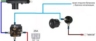
Do-it-yourself installation of glass closers on a VAZ
The closest one is designed to work in conjunction with a car alarm or other device that has a special output, on which a pulse of negative or positive polarity appears when the state of the system changes (for example, when arming).
To begin the installation, you need to check whether the car windows open and close with the buttons when the ignition is off; if not, you need to find the relay in the fuse block that is responsible for opening and closing the power windows, remove it and replace it with a jumper, as shown in the photo. Without this jumper, glass door closers will not work.
Rice. 1. Automotive fuse block and relay VAZ 2114
Rice. 2 A jumper instead of a power window relay is a guarantee that the closer will work for you.
After the preparatory stage, remove the driver's door trim (the passenger door trim remains in place)
Figure 3. Remove the driver's door trim to install the nearest one.
And install the nearest one on the car door as shown in the photo.
Rice. 4, Fig. 5. Installing the door closer module on the driver's door
Let's look at the installation diagram of door closers.
Fig. 6 Closer connection diagram
Figure 7. Comments on the connection diagram closest to the window.
And the electrical circuit of your car (for example, the closest one was installed on a VAZ 2114 car, we are only interested in a fragment with the same windows and appearance.
Connect the black wire to vehicle ground. Or, stupidly, to the black wire, because it is connected to ground.
We connect the white-yellow wire and the yellow wire to the central locking of your car.
We are looking for the wire responsible for opening the windows of the driver and passenger doors and connect their 4 wires in an empty space.
"Direct connection" means that the wire is cut in half and the connection is made from the button side and the motor side.
We cut the orange wire in half and connect the wires from the one closest to it on the button side. On the side of the button it is green with a black stripe, and on the side of the motor there is a green wire for the nearest glass.
We cut the blue one with a black stripe in half and connect the wires from the one closest to it on the button side. On the side of the button it is blue with a black stripe, and on the side of the motor there is a blue wire for the nearest glass.
All connections are carefully soldered and insulated.
We assemble the door trim and use door closers.
Troubleshooting procedure
- Check fuses F8 (20A) and F8 (20A) (mounting block).
- We check the serviceability of the rear window heating button. Is there a “plus” on pin No. 10 of the switch button and after turning on the button on pin No. 9 (a test lamp or multimeter will be useful).
- We check 12V at the output Ш5-2 and at the connector near the rear window.
- We check the wires and their connections.
- We check the rear window heating relay - K7.
- We check the integrity of the glass heating filaments.
The algorithm for determining the cause of a malfunction is similar for most cars, the only differences are in the names of fuses, relays and connectors.
By the way, do you know that to extend the service life of the heating elements, they use a Glass Heating Regulator (DOC), and you can also install a Fresnel lens on the rear window?
Source
Glass closer Pandora DWM
Connection diagram for the passenger door button in series through a duplicate button on the driver's door. Contacts 1-6 and 7-3 are always normally closed. When you press the up button, contacts 1-6 open and 1-2 close (window rises). When you press the down button, contacts 7-3 open and 7-2 closes (window down). The 30th contact of a 5-pin relay, without supplying voltage to the winding contacts, is constantly shorted to contact 88, which gives us the necessary negative contact (works like a switch). If voltage is applied to the winding, then contact 30 is disconnected from contact 88 and connected to contact 87. Contact 86 of the winding is connected to ground.
Drive unit
Drive shaft, CV joint (grenade), Outer CV joint, Inner CV joint, Right CV joint, Left CV joint, CV boot, Tripoid, CV joint nut, Retaining ring, Cardan, Crosspiece, Suspension bearing, Cardan bearing, Elastic coupling, Axle, Front axle, Rear axle, Axle reducer, Gearbox bearing, Gearbox oil seal, Differential, All-wheel drive sensor, Haldex coupling, Differential bearing, Differential oil seal, Planetary gears, Axle bearing, Axle shaft, Axle shaft bearing, Axle oil seal, Axle shank, Shank bearing, Axle bearing, Transfer case, Transfer case, Transfer case oil seal, Transfer case bearing, Transfer case chain
Recommendations
Comments 26
It’s not easier to open Google and write this question there. You'll do it much faster
Murzilka to help on the Internet there are a lot of wiring diagrams, take from 113-115 the diagram there is a pinout where and where
It can’t be any other way.
I connected 3 AA batteries, attached wires to the poles and looked for where + where -. and if you are going to install diodes instead of light bulbs, then to find + and - on the diode you will need current
the test will work too
also an option, but I simply don’t have it)))
I connected 3 AA batteries, attached wires to the poles and looked for where + where -. and if you are going to install diodes instead of light bulbs, then to find + and - on the diode you will need current
And I have a 12V pinatius block from St. tapes anado.ru/images/anado-cat…200_1/item/y08pbs7p0j.png (250 rubles) or you can buy a 12V battery, it costs 25 rubles.
Listen, I think I’m a little different
Listen, I think I’m a little different
How could it be different, if it were something else, then the stock backlight of the switches would not work.
but it’s easy, the button manufacturers are different, whose buttons even manage to turn on the ignition instead of the dimensions)
Everything with him is identical s011.radikal.ru/i317/1408/ed/87dc21eb059a.jpg. How will the switches manage to turn on the ignition if they do not close the circuit in parallel? If only someone climbed into the standard wiring and messed with it, then yes, but the wiring installed from the factory will not work.
everything just works out, read the forum, there are a lot of such complaints) and here on the drive there were some. because The headlights only light up when the ignition is on, apparently hence the connection that the plus button does not receive from the ignition, but feeds it back, and it turns on. so you can steal another 10s using the headlights/dimensions button
It won't go far, the steering wheel lock will work.
everything just works out, read the forum, there are a lot of such complaints) and here on the drive there were some. because The headlights only light up when the ignition is on, apparently hence the connection that the plus button does not receive from the ignition, but feeds it back, and it turns on. so you can steal another 10s using the headlights/dimensions button
and why the hell would you forgive me for this? I say that our headlight switches have different manufacturers, some of them work like factory ones, others turn on the ignition)
Yes, at least stick the jumpers in, but what the guy does in the video needs to be proven, half of the actions are not visible.
and why the hell would you forgive me for this? I say that our headlight switches have different manufacturers, some of them work like factory ones, others turn on the ignition)
People just came across or bought wiring on the market that has a discrepancy.
you did not understand. here in Samara2, the button WITHOUT ALTERATIONS does this kind of garbage, you don’t need any jumpers there, nothing. I bought a marker button (usually the one that is cheaper than from another manufacturer), you plug it in, turn on the markers, and instead of the marker the ignition turns on. That's it, no tricks or attempts to break into/steal. what the guy showed, there are no tricks there either, this is a factory jamb of the mounting block diagram in the 10th family
People just came across or bought wiring on the market that has a discrepancy.
Dear Drivers, yesterday I purchased a Euro panel. And the first thing that arose was how I could use my old wiring to install a panel on which there are buttons from a VAZ 211415. Having scoured the entire Internet in search of adapters from my old buttons to new ones, I couldn’t find anything and surrounded myself with a bunch of reference books and began to reinvent the wheel. Using information from the Internet and electrical circuits, I created something amazing =)
1) External lighting switch from VAZ 211415
2) Anti-fog button for front VAZ 211415.
3) Anti-Fog button for rear headlights VAZ 211415.
All other buttons will be standard. Good luck everyone! It may be useful to someone, otherwise there is not enough information on the Internet to replace the old panel with a euro =)
Lever window lift
One type of window lifting mechanism for the VAZ-2114, which, unfortunately, does not come from the factory, is a lever window lifter. These products are manufactured by Ningbo Stone.
These devices have proven themselves to be reliable and unpretentious mechanisms. Unlike cable window lifts, they have a greater lifting force. Glass frozen in winter is not a problem for them. They can handle them easily, while cable lifts experience significant stress on both the mechanism and the electrics.
One small disadvantage of the lever mechanism is that the speed of raising the glass is not the same. The higher the glass, the smaller it is. This is due to the geometry of the lifting mechanism. A good example would be scissors. If you take them by the rings and move the ends apart as much as possible, and then bring the rings closer to each other, it becomes clear that the height of the cutting ends changes faster when the rings are moved apart as much as possible. Conversely, the rate of ascent decreases as the rings move closer together.
It is this circumstance that allows this mechanism to create significant force. As we know from physics lessons, when you lose in distance traveled, you gain in strength. The same thing happens here: at the top of the range of motion, the distance traveled decreases and the lifting force increases.
The mechanism is driven by an electric motor and is connected as standard to the VAZ-2114 window lift circuit.