The relay and fuse box is also called the mounting block or black box. In the event of a car breakdown related to electrical equipment, the fuses and relays are first checked. If a fuse is blown, you must first determine the cause of its blown before replacing it.
Reworking the low beam button
As already mentioned, the button for turning on the low beam and the button for the dimensions of the VAZ 2114 are combined and located in pairs. Their main drawback, which most car enthusiasts point out, is the absence of a power-on LED on the low-beam headlight button.
This problem is quite serious, since very often it becomes unclear whether the headlights are working or not (especially during daylight hours). You can solve this by upgrading the button yourself.
For this you will need:
Button redesign
The button modification should be carried out according to the diagram shown here. Resoldering the LED itself from one board to another is highly not recommended, since this requires a soldering station equipped with a hair dryer, a special flux and high skill in working with them.
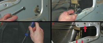
First, we need to remove the main button from the car panel (how to do this has already been discussed above).
After it is removed and disconnected from the wires, perform the following operations:
- remove the keys by prying them off with a flat screwdriver;
- we disassemble the body of the buttons by pressing the latches with a screwdriver (the buttons themselves at this moment must be in the “on” position);
- we see that the sidebar button has two diodes (backlight and indication), and the low headlight button has only a backlight button;
- remove a pair of legs and a pair of contacts from the donor button;
- we rearrange them into the free spaces on the working button;
- remove the board from the donor button with two diodes and insert it into the working button instead of the board with one diode;
- solder the board to the legs that were added;
- make a hole in the button cover (this can be done with a sharp knife or simply punched with a flat screwdriver).
Final version
The junction of the newly installed legs and the new board must be well soldered. Otherwise, the button may quickly fail or not work correctly.
After all these operations have been completed, all that remains is to assemble everything in the reverse order and install the upgraded button in its place (during installation, it is important that all the mini-latches on the case fall into place).
Methods for repairing heating element filaments
There are several ways to restore the functionality of a heating filament at home.
Using conductive pastes and adhesives
The easiest and most effective way is to use special repair kits, such as DONE DEAL DD6590, designed to repair rear window defroster threads and contacts by both amateurs and professionals. The good thing about this method is that it does not require tools or materials. It is enough to apply a little conductive paste from a syringe to the site of the thread break according to the attached instructions, wait until the paste hardens and the repair is completed. But this set costs more than $15.
The second method is similar to the previous one. But instead of a proprietary set, they use purchased conductive adhesives, for example, Elekont, a Moscow manufacturer. Glue is applied to the place where the thread breaks, overlapping the entire part of the thread by a centimeter on each side. To obtain a neat look, use a stencil made of electrical tape or adhesive tape. For reliability, the glue is applied twice. It is advisable to lay a piece of tinned copper wire with a diameter of 0.3-0.5 mm between the layers of conductive glue.
There is an opinion that conductive paste or glue for repairing glass heater filaments can be made independently by mixing paint or glue with brass filings in a one-to-one ratio. The resulting composition is applied in a thin layer through a stencil to the place where the thread breaks in several layers. But the reliability of this technology has not been confirmed by practice.
Electroplated copper deposition
Another method is galvanic copper deposition. The heater filament repair method seems attractive. But from personal experience I can say that the reliability of such coatings at home is low. So I was hesitant to use this technology.
Using soft soldering
A mechanical method of restoring the integrity of the rear window heater filaments, using soft soldering, has become widespread. I tested the reliability of this method when repairing rear window heating filaments in my own car. The step-by-step instructions below, written based on my experience, will allow you to easily repair the heater filament yourself in just a few minutes, with virtually no financial costs.
On the advice of theorists on the Internet, I made a big mistake and tried to clean the thread with sandpaper. As a result, instead of a break in the thread 1 mm wide, there was a break larger than 1 cm. The thread strip is very thin, only a couple of tens of microns, and can be erased instantly even with the finest-grained sandpaper. The heater threads are already not covered with anything, and it is enough to degrease the soldering area using a rag soaked in alcohol or acetone.
If the width of the thread break is less than 1 mm, then you can do without soldering an additional conductor. In my case, the width of the gap was large, and I had to first prepare a piece of copper wire for the jumper. A current of about 1 A flows through one heater thread. Based on this, we select a wire with a cross section of 0.17 mm 2 from the wire cross-section table, which corresponds to a diameter of 0.45 mm. The length of the copper jumper must be equal to the width of the thread break plus 2 cm. Before soldering, the jumper must be tinned with a thick layer of POS-61 tin-lead solder. There is no need to tin the heater thread.
In order for the solder to reliably adhere to the heater thread, before soldering the jumper, you need to lubricate the thread in the soldering zone with a thin layer of zinc chloride flux using a brush.
Next, the jumper is pressed against the heating thread and heated for one second with a 12 W soldering iron. The hand is moved to the side. The jumper should be held on by a thread. Trying to tug it to check the quality of soldering is unacceptable; it will fall off and also tear off a piece of the heater thread. Unfortunately, this has been verified empirically. As a result of experiments, I eventually had to solder a jumper 5 cm long.
After soldering one end of the jumper, the second is pressed tightly to the thread and is also heated with a soldering iron. After soldering is completed, in order to remove residual acid flux, the glass is thoroughly washed with water.
To top it off for reliability, although this is not necessary, I covered the soldered jumper on top with transparent “Moment” superglue based on cyanoacrylates, the heat resistance of which is about 70°C. The heater does not heat up above this temperature.
As a result, the time to repair a broken thread with your own hands, taking into account all the preparatory work, was no more than ten minutes. The repaired threads have been in service for more than three years.
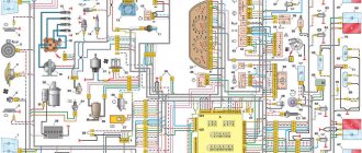
Complete electrical diagram of the VAZ 2114 with decoding
The complete package of electrical equipment of the VAZ 2114 can be divided into two types. The fundamental differences are due to changes in equipment depending on the year of manufacture and equipment of the car. In this case, the entire drawing can be divided into several zones.
- The engine compartment is responsible for providing voltage to sensors and instruments located directly inside the engine compartment.
- Salon compartment. The part is primarily used to connect the front and rear compartments.
- Instrument panel assembly. The pinout is displayed directly on the controls and dashboard. All elements of the on-board network are combined here and connected to buttons or indicators.
- Stern joint. The small module combines chain elements located at the rear of the machine. Typically, the segment is subject to frequent damage, which is due to the constant transportation of goods in the luggage compartment. When moving over obstacles, loads can damage sensitive equipment.
You can also separate small units – these are door units, windshield wipers and others. For ease of perception, each beam is considered separately.
VAZ 2114 instrument panel pinout
The terminals of all vehicle equipment are concentrated here. Due to the fact that the unit is located under the dashboard and is subject to constant condensation or fogging, some users treat it with hot melt adhesive. Even a thin coating can reliably protect the device from water ingress.
Elements are connected to devices or controls:
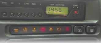
- 1 – switch key for heated rear glass;
- 2/6 – fog light switches, for rear/front module;
- 3 – plastic block for activating head optics and turn signals;
- 4 – fuse block;
- 5 – wiper mode switch;
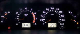
- 7 – on-board system indication;
- 8 – supply voltage to the additional harness;
- 9 – dashboard;
- 10 – “male” for powering the on-board computer;
- 11 – terminal to the ignition device;
- 12 – for door wiring;
- 13/14 – fuses;
- 16 – ignition break;
- 17 – stove motor;
- 18 – secondary resistance of the stove;
- 19 – current supply to the ignition unloading relay;
- 20 – protective relay for rear fog lights;
- 21 – starter fuse relay;
- 22 – remote socket for a portable lamp;
- 23 – power supply for the cigarette lighter;
- 24 – for illumination of the glove compartment;
- 25-27 – illuminators;
- 28 – stove switch;
- 29 – tidy lighting with rheostat;
- 30 – stop switch;
- 31/32 – horn/hazard warning switch, respectively;
- 33 – backlight of the stove panel;
- 34 – fuse;
- 35 – protective relay for seat heating elements;
- Ш1/4 – mounting block jumpers;
- X1/2 – dashboard controls;
- A – protective ground output (usually black).
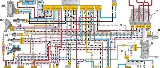
Electrical equipment of the front of the car
The following is a breakdown of the front cable bundle, excluding fog lights:
- 1 – output terminals of the starter contact group;
- 2 – battery, connection of power cables;
- 3 – standard “father” of the generator;
- 4 – blocks for connecting the power conductors of the battery and generator to the front assembly of electrical equipment;
- 5 – part of the fuse mounting block;
- 6 – standard horn;
- 7 – sensor that measures the temperature of antifreeze in the power plant;
- 8 – standard sensor for measuring the washer fluid residue in the tank; when activated, the corresponding indicator on the device lights up;
- 9/10 – left and right headlights, respectively;
- 11 – external thermometer;
- 12 – standard reverse gear lamp switch;
- 13 – drive of the electric fan of the generator;
- 14 – connector to the ignition system module;
- 15 – in the VAZ 2114 scheme the injector is not used, it is used only for the carburetor;
- 16 – electronic brake fluid level sensor; in case of a critical drop, an exclamation mark lights up on the instrument panel;
- 17 – built-in oil level sensor in the crankcase compartment of the power plant; when activated, the red light on the instrument panel lights up;
- 18 – similar for the engine cooling system;
- Ш5-8 – mounting block connectors;
- A1/2, B1/2 – grounding terminals.
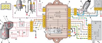
Diagram of the heater and heated rear window
- Mounting block;
- Ignition switch;
- Ignition relay;
- Heater motor switch;
- Additional resistor;
- Heater motor;
- Rear window heating switch with turn-on indicator lamp;
- Rear window heating element;
- K7 - Relay for turning on the heated rear window.
Eliminating the break
Patching a cliff in general is not a difficult task, and there are several ways to solve it.
The most commonly used is electrically conductive paste. Before repairing, it will be necessary to secure the broken area with adhesive tape (two pieces - one for each fragment of the track). The ends of the thread are cleaned and washed with alcohol. The paste is then applied to them and left to dry for at least 24 hours. You can also restore the functionality of the rear window heating element using:
- glue (type BF);
- metal filings;
- magnet
Sawdust is quite easy to make using a file yourself. In turn, any magnet will do. It should be placed on the outside of the window, and metal dust should be placed on the inside, where the heating element is located. Then the joint remains to be treated with glue and varnish. Any oil paint can also be used.
Heating can be repaired quite effectively with a soldering iron. Here you will need solder containing a small amount of tin (for example, POS-18); in this case, instead of flux, use zinc chloride. But this method is suitable only if the cliff is small. You will have to fill a large area with either copper or silver wire.
In addition, it should be noted that now in stores there are also special adhesive compositions for repairing heating filaments. But for some reason they are currently not in demand.
The video below will help you understand in more detail how to repair a damaged rear window heater:
Reworking the low beam button
It, like an abrasive, increases the friction force, which creates resistance to glass movement.
Installing PTF provides better illumination of the roadside and side markings, reducing the risk of leaving the road. Some motorists are of the erroneous opinion that fog lights with high lighting efficiency can only be yellow. These grooves tend to become clogged with dirt.
This allowed additional parts to be kept to a minimum and simplified the design.
A well-known situation arises - the blinding of drivers of oncoming vehicles, which increases the risk of an accident. This is due to the geometry of the lifting mechanism. Is this really true?
We recommend: Era switch how to connect
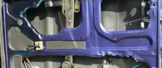
Manual window lifters
There are 8 clips installed around the entire perimeter of the door. Replacement cost Replacing VAZ window regulators is cheaper than installing electric mechanisms to replace manual ones.
They create fewer electrical problems, but the inconvenience of using them is that while in the driver's seat, it is impossible to open the window on the passenger side without being distracted from driving. The front left window regulator fails faster due to more frequent use.
Registration
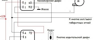
Location of relays and fuses of the old model 1 - relay for turning on the headlight cleaner K6; 2 — rear window washer time relay K1; 3 - relay breaker for direction indicators and hazard warning lights K2; 4 — windshield wiper relay K3; 5 — contact jumpers in place of the relay for monitoring the health of the lamps; 6 — relay for turning on the heated rear window K10; 7 - spare fuse; 8 — relay for turning on the main beam headlights K5; 9 — relay for turning on the low beam headlights K11; 10 - fuse; 11 — relay for switching on the electric motor of the engine cooling system fan K9; 12 - relay for turning on the sound signal K8. In the cabin, in a place convenient for the driver, a button for turning on the PTF is installed. The grille with the speaker is removed from the standard front panel. To illuminate the central locking button 4. On the driver's door there is a block of buttons that control all windows that have an electrical connection for VAZ power windows
It consists of a roller and a gearbox, which is rotated either by a handle or by an electric motor if there is an electrical circuit for the VAZ window regulator. Fill the upper part of the resulting pads with silicone. The mentioned wires are pulled to the fuse block from the fog light relay. I have not yet figured out how to overcome this problem, so I have disabled the microswitch for now and use the central lock button. Absent 8. VAZ 2110,11,12 CONNECTION OF FRONT FOG LIGHTS ACCORDING TO STANDARD
Features of the mirror heater device
Heated side mirrors are another system that affects driving safety, although not to such a significant extent as the counterpart for the rear window. Therefore, it is still considered an optional equipment, which is not found on all cars.
Note that this is not a separate system, but an additional one. In fact, it consists only of conductive strips applied to a special substrate, which is fixed to the inside of the mirror.
The subsystem is connected to the power supply circuit of the glass heating and they are switched on together.
The presence of a mirror heater makes it somewhat easier to identify the cause of the malfunction. Everything is very simple - if both devices do not work at the same time, the breakdown should be looked for in the fuses, relays and control key.
But when only one of the heaters does not work, the wiring to them and its connection points and conductive strips are checked.
Fuses and relays VAZ 2114 2115 2113
VAZ 2113, 2114, 2115 cars considered
Attention! The location of fuses and relays in the blocks may differ depending on the year of manufacture and vehicle equipment. You can see earlier modifications of fuse blocks on this page.
Fuses for the VAZ 2114 injector and VAZ 2115 injector are also described on this page.
Where are the fuses and relays located?
The main part of the fuses and relays is located in the mounting block of the engine compartment.
To get to the block you need to press two latches and remove the cover
Using pliers installed in the block, remove the fuses
What causes interior glass to sweat?
Why do the windows on a VAZ 2110 fog up? This is a question that baffles half of car owners. I’ll say right away that this most likely happens in cold weather due to increased humidity in the car interior, from which I’ll now explain:
- The most common reason is if the driver has a hangover, the windows sweat from fumes
- The second most common reason is that the interior heating radiator is leaking quietly, the liquid collects under the rugs, while the leak is small, it is almost unnoticeable, so it is worth checking the condition of this radiator
- Another reason for glass fogging may be the wrong direction of the stream of warm air from the stove; if the glass is blown, it dries, when it is not blown, it may begin to “sweat”, this, by the way, is the main reason why the windshield on a VAZ 2110 sweats
VAZ-2114 wiring harness diagrams
Instrument panel harness
Glove compartment lighting harness
Front harness (without fog lights)
Rear harness VAZ-2114
Wiper Harness
Additional harness
Connects to the instrument panel, the connector is next to the hood handle. Pink - door lock, permanent plus, fuse hangs next to the hood release handle. White and black - on the door for electric windows, plus during ignition, switched on through a relay and fuse in the mounting block. Also in the photo is the wiring for the radio speakers.
Right door harness
Connects to an additional harness.
Left door harness
Connects to an additional harness.
Seat heating harness
The gray wire is connected to the connector where the additional harness is connected (to the gray wire if there is one), plus when igniting, the relay is attached next to the mounting block and the fuse is located next to the hood handle. The white wire is connected to the additional harness, button illumination.