To ensure safe and stable thermal conditions of an internal combustion engine, precise operation of the cooling system is required. The slightest failure will lead to overheating of the engine, which can lead to burnout of the head gasket or failure of the piston group elements.
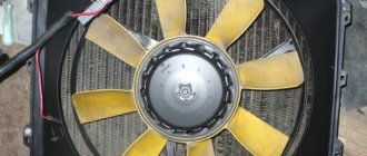
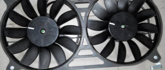
The radiator fan is one of the key components of the car cooling system. Its role is to promptly force cool the liquid in the radiator. Problems with turning it on are a common occurrence for our cars.
In this article we will talk about possible reasons why the VAZ-2110 cooling fan does not work, and also consider options for eliminating them. But first, let's understand its design and operating principle.
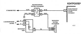
Circuit diagram for switching on the cooling fan for a VAZ 2110 carburetor engine.
The circuit diagram for switching on the cooling fan of the VAZ 2110 on carburetor and injection cars is different. On cars with a carburetor engine, a thermobimetallic sensor TM-108 is used for this, and on cars with an injection engine, control is carried out by a controller.
When the fan is controlled by a sensor, the switching temperature depends on the sensor setting temperature, which is indicated on the housing. If the fan does not turn on when the temperature rises to the sensor response temperature, you must first check the serviceability of the sensor. To check, just close the contacts on the sensor and if it turns on, you need to change the sensor. If after closing the terminals the fan does not work, then the cooling fan switching circuit and the integrity of the fuse need to be checked.
VAZ 2110 - modifications
VAZ-21100 . The base model which was produced from 1996 to 2000. The car was equipped with an 8-valve carburetor VAZ-21083 engine with a displacement of 1.5 liters and a power of 69 horsepower.
VAZ-21101 . This modification has been produced since 2004, equipped with an 8-valve gasoline injection engine with a displacement of 1.6 liters.
VAZ-21102. Like the previous modification with an 8-valve injection engine, but with a volume of 1.5 liters.
VAZ-21103 . Modification of the “tens” with a 16-valve injection engine with a working volume of 1.5 liters.
VAZ-21103M . A restyled modification of the VAZ-21103, equipped with a 16-valve petrol injection engine with a displacement of 1.5 liters and a power of 92 horsepower. Produced since 2002.
VAZ-21104 . The modification is equipped with a 16-valve petrol injection engine with a working volume of 1.6 liters.
VAZ-21104M . A restyled modification of the VAZ-21104, equipped with a 16-valve petrol injection engine with a displacement of 1.6 liters. Produced since 2004.
VAZ-21106 GTI . The engine of the VAZ-21106 GTI is the most powerful and expensive modification that has been produced since 2000. The car was equipped with a 2-liter 16-valve Opel C20XE gasoline engine with a capacity of 150 horsepower. The car was fitted with a body kit with swollen arches, and the track was widened by 76 millimeters. It was equipped with R15 wheels with low-profile tires.
VAZ-21106 Coupe . Coupe VAZ-21106 in a coupe body. A distinctive feature of the car was the presence of only two doors, which were lengthened by 250 millimeters, while the body was shortened by 170 millimeters. The engine was installed the same as in the previous VAZ-21106 GTI model.
VAZ 21106 WTCC . A sports modification of the 106 model, it participated in the 2008 FIA WTCC international championship.
VAZ 21107 . Modification of a car for rally competitions. It was equipped with a welded safety cage and a different suspension design.
VAZ 21108 "Premier" . A modification with a body lengthened by 170 millimeters in the rear door area, which provided more convenient entry and exit of passengers. It was equipped with a 1.5-liter injection 16-valve engine.
VAZ 21109 “Consul” . 4-seater luxury limousine based on the VAZ-2110 car. In addition to the length of the body, the dimensions of the rear door were also increased, for more convenient entry and exit of passengers. Equipped with a 1.5 liter engine and R14 or R15 wheels. Overall dimensions: length - 4950 mm, width - 1700 mm, height - 1440 mm. Fuel consumption in the urban cycle is 9.5 liters per 100 kilometers.
VAZ 2110-91 . Modification of the VAZ-2110 with a 1308 cm3 rotary piston engine. The car could reach speeds of up to 240 km/h, and acceleration from 0 to 100 km/h took 6 seconds.
A car with a 16-valve injection engine in the Gran Lux configuration includes:
- Electric windows;
- Door locking;
- Trunk lock lock;
- Velvet seat upholstery;
- Immobilizer;
- Heated front seats;
- Ventilated 14-inch brake discs;
- Rear spoiler with additional brake light;
- Fog lights.
The fan does not turn on.
But there are malfunctions in which the controller does not recognize the malfunction and the fan may not turn on when the temperature reaches above 105 degrees. C. In this case, to check the circuit and sensor, it is necessary to remove the connector from the temperature sensor while the engine is running. If the circuit is working properly and the sensor is malfunctioning, the fan will turn on and turn off when the connector is returned to its place.
If the circuit malfunctions, it is necessary to check the integrity of the fuse, the serviceability of the relay and wires, according to the circuit. For a quick check, you need to bridge terminals 30 and 87 of the fan relay, located in the heater shaft on the passenger side. If the fan works, without removing the relay from the block, connect the case and pin 86 of the relay with a test lamp, the relay should work and the fan should turn on. In this case, the controller or the wire connecting the relay to pin 46 of the controller is faulty.
If you do not hear the characteristic click of the relay turning on, and a positive signal is supplied from the main relay to pin 85 of the relay, and if there is a click and the fan does not turn on, change the relay. When installing a jumper between pins 30 and 87 does not turn on the fan, check the integrity of the fuse and the presence of power at the fan terminals. If there is power on one terminal and no power on the other, this indicates a possible malfunction of the fan motor.
Scheme for switching on the cooling fan of an injection engine.
- Connection diagram for a fan with a timer: operating principle and connection order
06/09/2011 “If you notice an error in the text, please highlight this place with the mouse and press CTRL+ENTER” “If the article was useful to you, share the link to it on social networks”
To ensure safe and stable thermal conditions of an internal combustion engine, precise operation of the cooling system is required. The slightest failure will lead to overheating of the engine, which can lead to burnout of the head gasket or failure of the piston group elements.
The radiator fan is one of the key components of the car cooling system. Its role is to promptly force cool the liquid in the radiator. Problems with turning it on are a common occurrence for our cars.
In this article we will talk about possible reasons why the VAZ-2110 cooling fan does not work, and also consider options for eliminating them. But first, let's understand its design and operating principle.
What to do when the fan runs constantly
There are situations when the cooling radiator works without interruption, both on a hot and cold engine. The reasons can be very different. Now we will look at the main problems and ways to solve them.
- A break in the sensor that monitors the antifreeze temperature readings or its circuits. In this case, the Check engine light comes on. The circuits and sensor are checked with an ohmmeter. The problem is solved by replacing the element with a new one.
- The fan relay contacts open. First, the component is checked with a multimeter and, if necessary, replaced with a new one.
- Malfunctions in the ECU. Check this node on the profile service. If a malfunction is detected, the firmware or the unit is changed completely.
- In VAZ carburetor models, the thermal switch contacts do not open. To check operation, disconnect the terminals from the terminals of this unit - and the fan will stop. In this case, it is necessary to replace the faulty part.
If the tests carried out have not determined why the fan is constantly running, then the only possible way out of the situation is to contact a service center.
Full-fledged service stations, as a rule, conduct a full computer check of the cooling system, which can identify the most difficult to detect faults. The failure can be much more global than a normal fuse failure.
If the usual testing steps do not produce any results, then you should not be afraid to contact the service, and even in cases where you consider yourself an experienced technician. Often, modern equipment and a professional approach significantly reduce the troubleshooting time. Whereas conventional methods would take weeks to determine the problem. Therefore, car services have their own advantages.
The design and circuit diagram of the radiator fan may differ not only depending on the make of the car, but also on the year of manufacture and model configuration. Let's consider not only the principle of operation, but also the connection option with the possibility of forced activation of the cooling system fan (VSO).
Fan connection diagram in carburetor and injection engines
The control of forced radiator airflow in carburetor and injection engines of the VAZ-2110 is significantly different. Firstly, the fan switch located on the radiator housing is responsible for everything. It is set to a certain coolant temperature. Usually it is 105-107 oC. When the coolant heats up to this temperature, the sensor is triggered, sending a signal to the fan relay. It closes the electrical circuit, driving the electric motor.
- Scheme for switching on the cooling fan VAZ 2107 carburetor
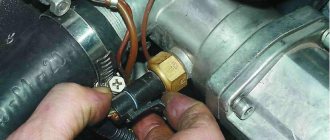
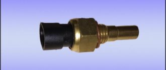
Turning on the cooling fan of a VAZ-2110 with an injection engine occurs somewhat differently. In engines equipped with an electronic control unit, there is no sensor on the radiator. Its place was taken by a temperature sensor located on the thermostat pipe. When the coolant heats up to a temperature of 105-107 oC, it sends a signal directly to the controller, which makes the decision to turn on the fan. It transmits an electrical impulse to a relay, which turns on the electric drive.
Cooling system design features
Depending on the design features, the fan can be turned on in 3 ways:
- using a power sensor for activation of the VSO. This sensor is also called a fan temperature relay, since the power contacts of the electric motor pass directly through the sensor. With this scheme, the load on the thermal relay increases significantly, which reduces its service life;
- using the fan switch sensor, but now closing the contacts in the temperature switch triggers the relay, through which the power contacts of the cooling fan are connected. This connection method is much more reliable than the previous option;
- using an electronic engine control unit. The ECU, focusing on the coolant temperature sensor installed in the engine cooling radiator, supplies power to the VCO through a relay. A resistive temperature sensor is used as a meter. It is this switching circuit that is used on the vast majority of modern cars. On cars equipped with air conditioning, one of the electric fans will be controlled by the comfort unit. This is necessary for forced cooling of the condenser when the interior air conditioning system is activated.
Operating modes
When understanding the operating principle and connection diagram of a radiator fan, you should remember that electric motors often have two speed modes. This is implemented in 2 ways:
- by adding a resistor to the circuit, which increases the resistance and, as a result, reduces the current. The design uses a two-contact sensor, which, depending on the temperature, powers the electric motor directly or through resistors;
- a combination of parallel and series connection. The circuit is used on a car with two fans. They can be connected in series, in which case, according to Ohm's law, they will operate from 6 V, or in series, when 12 V is supplied to each of the VSOs. The modes correspond to low and high speed rotation of the propeller.
Possible faults
If the VAZ-2110 cooling fan does not work, do not rush to contact a car service center. You can determine the cause of the malfunction yourself. Moreover, it is not at all necessary to have special skills for this.
The cooling system fan may not turn on due to:
- electric drive malfunctions;
- blown fuse;
- faulty thermostat;
- a failed fan switch (temperature);
- faulty relay;
- broken electrical wiring;
- faulty expansion tank plug.
How to check the thermostat
The function of the thermostat in an internal combustion engine is to regulate the flow of coolant, directing it in either a small or large circle. While the engine is cold, its valve blocks the flow of coolant into the cooling radiator. This allows the engine to warm up faster.
When the coolant warms up, the thermostat valve opens, directing it to the radiator for cooling. If the valve jams, the coolant constantly moves in a small circle, not reaching either the fan switch sensor or the temperature sensor. In this case, the liquid may even boil, but the sensors, being uninvolved in such a circuit, will not work.
Check the thermostat by determining the temperature of its pipes by touch. When the engine is warm, they should all be hot. If the pipe leading from the thermostat to the cooling radiator is cold, the locking device is faulty.
- Installation on VAZ 2108 and 2109 with a low torpedo instrument cluster from 2115
How to check the sensor
One of the most common reasons why the VAZ-2110 cooling fan does not turn on is a non-working sensor for its activation (for carburetor engines) or a temperature sensor (for injection engines). Let's consider ways to check them for different engines.
In a car with a carburetor engine, you must turn on the ignition and short-circuit the two wires going to the sensor. The fan should turn on. If this does not happen, the problem is definitely not with the sensor.
For injection cars, it is necessary to warm up the engine to operating temperature and disconnect the sensor connector, disconnecting it from the vehicle’s on-board network. In this case, the controller must start the fan in emergency mode. The electronic unit perceives this as a failure in the cooling system and forces the fan drive to operate in constant mode. If the drive starts, the sensor is faulty.
Scheme options
Schematic diagram of VSO connection on VAZ 2108, 2109, 21099 (until 1998).
As we can see, the sensor controls the fan relay, which is located in the fuse box. When a certain temperature is reached, the contacts of the temperature switch close, which leads to the flow of current in the electric motor circuit.
Above is a diagram for VAZ 2108, 2109, 21099 cars, but after 1998. As we can see, the power sensor now functions as a relay.
Let's consider a circuit using a resistor to implement two propeller rotation speeds using the VW Passat as an example. The two-position fan power sensor S23, depending on the coolant temperature, closes the contacts directly or through an additional resistance.
DIY connection
Some drivers, warning the engine against malfunction of the radiator fan power supply thermal relay, make a remote button to force the electric motor to turn on. To do this, it is enough to connect a fixed button in parallel to the control output of the relay coming from the sensor, which, when pressed, will close the contact to ground, thereby provoking the operation of the relay. If the car's design does not provide a fan relay, you will have to install it yourself to force cool the radiator.
Under no circumstances should you connect the electric motor directly through the button in the cabin! We also do not recommend connecting the circuit so that after turning on the ignition the electric fan constantly rotates, as this significantly reduces its service life.
To connect, you only need to understand the operating principle of a 4-pin relay and minimal knowledge in installing additional equipment. Be sure to include a fuse of the required rating in the power circuit and place it as close to the power source as possible (read more).
If desired, you can replace the single-position sensor with a two-position one, which, paired with a selected resistor, will allow you to realize a low speed of operation of the VSO. If you have a sufficient level of knowledge in electrical engineering, then you can build a PWM controller to adjust the speed of rotation of the propeller. Controlling the electric fan using a PWM signal will allow you to smoothly regulate and arbitrarily select the rotation speed depending on the temperature load on the engine. There is enough material on the Internet on how to make a PWM controller with your own hands.
How to turn on the fan from a button on a VAZ-2106 is a pressing question in the hot season. Meanwhile, making such a modification is not so difficult.
There are two types of cooling fans on the VAZ-2106. On old “sixes” they were mechanical, driven by the engine crankshaft, and on newer cars they were with an electric motor and an automatic switching sensor. A mechanical fan is more reliable in hot weather, but is completely unnecessary in winter, which is why it was replaced by its electric “brother”.
The second defroster button actually turns on the engine cooling fan.
The electric cooling fan on the “six” is activated by the activation of a sensor installed in the main radiator. But often this sensor fails and then there is a threat. That is why it is worth making a button to turn on the fan in the interior of the VAZ-2106. How to make such a system?
The point of this modification is to run your own parallel to the factory power line and “along the way” install a button in the cabin. To understand how this should work, let’s take a closer look at the principle of operation of the cooling fan on a classic.
The fan switch sensor is located in the right (in the direction of travel of the car) tank of the main radiator from below. It is purely mechanical, that is, there is no electronics inside. When the antifreeze in the radiator is heated to a certain temperature (the sensors are different, but on average it is 92 degrees), the contacts inside the sensor close and voltage is supplied to the fan relay.
To organize the activation of the engine cooling fan from a button in the cabin, you need to be able to supply voltage to the relay directly, bypassing the sensor in the radiator. This will require about seven meters of wire, electrical tape, pliers and screwdrivers.
With the engine not running, remove one of the two wires from the fan switch sensor and bite off its terminal. , and clamp the factory wire and our own into the new terminal, which we will later lead into the interior. We securely crimp the terminal, insulate it with electrical tape or put on a standard factory rubber band and put it on the sensor.
When the hole for the button is ready, connect the button itself. It needs to be connected. This circuit not only allows you to turn on the fan, but also lights up an orange indicator inside the key.
After the key is connected and installed in the new hole, the rest of the wire must be routed back to the sensor in the radiator and connected in the same way through the new terminal to the second factory wire of the sensor. The result is a parallel circuit.
Now turn on the battery, ignition and press the button. If everything is done correctly, the cooling fan will turn on at any engine temperature. This happens because now the current can pass not through the sensor, but bypass it through new wires. By pressing a button, we seem to simulate the operation of a sensor in the radiator and, accordingly, do not depend on its performance.
Turning on the engine cooling fan from a button in the cabin is a very convenient thing. However, relying on it completely, replacing automatic switching on with it, is not always convenient, because you will have to constantly monitor the engine temperature. In conditions, for example, in a big city, there is often simply no time to look at the devices, so it is better to use the constructed system as an auxiliary one, which will come to the rescue if the factory sensor suddenly fails.
To ensure safe and stable thermal conditions of an internal combustion engine, precise operation of the cooling system is required. The slightest failure will lead to overheating of the engine, which can lead to burnout of the head gasket or failure of the piston group elements.
The radiator fan is one of the key components of a car's cooling system. Its role is to timely forced cooling of the liquid in the radiator. Problems with turning it on are a common occurrence for our cars.
In this article we will talk about possible reasons why the VAZ-2110 cooling fan does not work, and also consider options for eliminating them. But first, let's understand its design and operating principle.
Checking the cooling fan relay
The most difficult step in troubleshooting a fan is determining the functionality of its relay. It is only relatively possible to establish its serviceability at home. But you also need to know where the cooling fan relay is located.
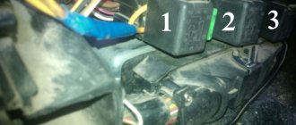
And it is located in the additional mounting block of the center console. On the lower left side of the front passenger side there is a plastic cover covering the console. To open it, you need to unscrew four screws. There are three relays under the cover. The leftmost one is responsible for turning on the cooling fan. You can check it only by installing a known-good device in its place. After the engine has warmed up to the sensor response temperature, wait for a characteristic click. If the cooling fan relay does not work, you need to check the wiring.
How to check wiring
Finding a broken conductor in a car's electrical circuit yourself is not at all difficult. It is necessary to check (ring) all wires in the indicated areas with a tester.
For carburetor engines:
- from the switch on sensor to the fan;
- from the fan to the mounting block (fuse);
- from the mounting block to the relay.
For injection engines:
- from the main relay to the fan switch relay;
- from the switching relay to the fan and controller;
- from temperature sensor to controller;
- from the fan to the mounting block (fuse).
If a wiring break is detected, it must be restored, as well as the possible cause of the circuit break must be identified and eliminated.
Heater control circuit 2110
1 – fan electric motor; 2 – additional resistor; 3 – controller; 4 – mounting block; 5 – ignition switch; 6 – cabin air temperature sensor; 7 – recirculation switch; 8 – recirculation valve; 9 – micromotor gearbox for heater damper drive; A – to the instrument lighting switch; B – to power supplies
Expansion tank cap
The last reason why the VAZ-2110 cooling fan does not work may be a malfunction of the expansion tank cap. The fact is that when the engine is running, a pressure above atmospheric pressure is created in the cooling system, due to which the water, which is part of the coolant, does not boil at 100 ° C. The expansion tank cap valve is designed to maintain the required pressure. If it fails, the pressure in the system will be equal to atmospheric pressure. This will cause the coolant to begin to boil already at 100 degrees. A sensor designed to turn on at a higher temperature will naturally not work.
It is unlikely that you will be able to check the operation of the cover at home, so if during a visual inspection you have doubts about its functionality, it is better to replace it immediately.
The principle of operation of the cooling system of the VAZ 2110 injector 16 valves
The design is a closed circuit, inside which coolant is pumped through a centrifugal pump. The radiator releases the temperature generated by the engine into the atmosphere. The sensor installed on the thermostat pipe senses the coolant heating threshold of 105 - 107 degrees Celsius, provides information to the controller. The controller sends a signal to the relay, starting the electric motor of the fan. The radiator honeycombs are blown.
The principle of operation of the cooling system of the VAZ 2110 injector 16 valves: 1 - heater radiator; 2 — coolant drain hose from the heater radiator; 3 — coolant supply hose to the heater radiator; 4 — coolant pump hose; 5 — expansion tank hose; 6 — steam removal hose of the heater radiator; 7 — expansion tank cap; 8 — expansion tank; 9 — thermostat; 10 — coolant drain hose from the engine radiator; 11 — hose for supplying fluid to the throttle assembly; 12 — steam exhaust hose of the engine radiator; 13 — hose for supplying fluid to the engine radiator; 14 — engine radiator; 15 — radiator drain plug; 16 — electric engine radiator fan; 17 — coolant pump; 18 — supply pipe of the coolant pump; 19 — coolant drain hose from the throttle body.
Safety regulations
- Open the expansion tank cap after the engine has cooled down.
- When working under the hood, beware of rotating blades and a hot engine.
- Use auxiliary, serviceable conductors with a cross-section of 2 mm.
- Use standard fuses of the required rating.
- Use a proper tool.
- Insulate “bare” contacts, avoiding short circuits in the electrical wiring.
Electric sema VAZ 21102
| 1 — block headlight | 35 — instrument lighting switch |
| 2 - front brake pad wear sensors | 36 - ignition switch |
| 3 - reverse light switch | 37 - mounting block |
| 4 — electric motor of the engine cooling system fan | 38 - recirculation valve switch |
| 5 - sound signal | 39 — heater controller |
| 6 — gear motor for locking the right front door lock | 40 - hazard warning switch |
| 7 - power window relay | 41 — lamp illuminating the heater control levers |
| 8 - 8 A fuse | 42 — glove box lighting lamp |
| 9 - starter | 43 - glove compartment light switch |
| 10 - accumulator battery | 44 - cigarette lighter |
| 11 - generator | 45 — display unit of the on-board control system |
| 12 - windshield washer motor | 46 - ashtray lighting lamp |
| 13 — washer fluid level sensor | 47 — brake light switch |
| 14 — gear motor for locking the left front door lock | 48 — gear motor for locking the left rear door lock |
| 15 - left front door power window switch | 49 - left rear door power window switch |
| 16 — coolant level sensor | 50 — electric window motor of the left rear door |
| 17 - windshield wiper motor | 51 — socket for a portable lamp |
| 18 - recirculation valve | 52 - watch |
| 19 — micromotor gearbox for heater damper drive | 53 — electric window motor gearbox of the right rear door |
| 20 — electric heater motor | 54 — right rear door power window switch |
| 21 — trunk lock switch | 55 — gear motor for locking the right rear door lock |
| 22 - right front door power window switch | 56 - side turn signal |
| 23 — electric window motor reducer of the right front door | 57 - parking brake warning lamp switch |
| 24 — control unit for the door lock system | 58 — driver's seat belt sensor |
| 25 — additional resistor for the heater motor | 59 - directional lamp |
| 26 — brake fluid level sensor | 60 - interior lamp |
| 27 — electric window motor reducer of the left front door | 61 — cabin air temperature sensor |
| 28 - outdoor lighting switch | 62 — switch in the front door pillar |
| 29 — instrument cluster | 63 — switch in the rear door pillar |
| 30 - rear fog light switch | 64 — external rear light |
| 31 — fog light indicator lamp | 65 - internal rear light |
| 32 — indicator lamp for heated rear window | 66 — license plate lights |
| 33 — rear window heating switch | 67 - trunk light |
| 34 - Understeering's shifter |
A
— blocks for connecting the rear window washer motor.
B
- blocks for connecting the injection system harness.
C
- to the warning light harness block.
D
— block for connection to the on-board computer.
E
- to the headlight cleaner harness block.
F
— block for connection to the fuel level sensor in the electric fuel pump module.
G
- to the rear window heating element.
H
- block for connecting an additional brake signal.
J
- to the trunk lock motor.
The diagram does not conventionally show that in the instrument panel wiring harness, the second ends of all wires of white, black, orange, white with a red stripe and yellow with a blue stripe are connected to each other at the same points.
Connection diagram of the engine management system 2111 with distributed fuel injection of the VAZ-21102 car
- 1 – injectors 2 – spark plugs 3 – ignition module 4 – diagnostic block 5 – controller (since 2000, a modification of the system with M1.5.4N or “January-5.1” controllers has been produced) 6 – cooling system fan electric motor 7 – block attached to instrument panel wiring harness 8 – main relay 9 – fuse connected to the main relay 10 – electric fan relay 11 – fuse connected to the electric fan relay 12 – electric fuel pump relay 13 – fuse connected to the electric fuel pump relay 14 – mass air flow sensor
- 15 – throttle position sensor
- 16 – coolant temperature sensor
- 17 – CO potentiometer (not installed on vehicles with a modified control system, CO adjustment is carried out using the DST-2 device through the diagnostic block)
- 18 – idle speed regulator
- 19 – knock sensor
- 20 – crankshaft position sensor
- 21 – vehicle speed sensor
- 22 – immobilizer control unit
- 23 – immobilizer status indicator
- 24 – electric fuel pump with fuel level sensor
- 25 – oil pressure warning lamp sensor
- 26 – coolant temperature indicator sensor
- 27 – oil level sensor
- 28 – knock sensor (installed on vehicles with a modified control system)
Fuse box VAZ-2110, VAZ-2111, VAZ-2112
F1 - 5A - License plate lamps. Instrument lighting lamps. Side light indicator lamp. Trunk light. Left side marker lamps. F2 - 7.5A - Left headlight (low beam). F3 - 10A - Left headlight (high beam). F4 - 10A - Right fog lamp. F5 - 30A - Electric door window motors. F6 - 15A - Portable lamp. F7 - 20A - Electric motor of the engine cooling system fan. Sound signal. F8 - 20A - Rear window heating element. Relay (contacts) for turning on the heated rear window. F9 - 20A - Recirculation valve. Windshield and headlight cleaners and washers. Relay (coil) for turning on the heated rear window. F10 - 20A - Reserve. F11 - 5A - Starboard side marker lamps. F12 - 7.5A - Right headlight (low beam). F13 - 10A - Right headlight (high beam). Indicator lamp for turning on the high beam. F14 - 10A - Left fog lamp. F15 - 20A - Electric seat heating. Locking the trunk lock. F16 - 10A - Relay-breaker for direction indicators and hazard warning lights (in emergency mode). Hazard warning lamp. F17 - 7.5A - Interior lighting lamp. Individual backlight lamp. Ignition switch illumination lamp. Brake light bulbs. Clock (trip computer). F18 - 25A - Glove box lighting lamp. Heater controller. Cigarette lighter. F19 - 10A - Door locking. Relay for monitoring the health of brake light lamps and side lights. Direction indicators with warning lamps. Reversing lamps. Generator excitation winding. On-board control system display unit. Instrument cluster. Clock (or trip computer). F20 - 7.5A - Rear fog lamps.
There are no fuses in the starting circuit.
Relay designation:
K1 – relay for monitoring the health of light bulbs; K2 – front wiper relay; K3 – repeater and alarm relay; K4 – low beam relay; K5 – high beam relay; K6 – additional relay; K7 – relay for turning on the heated rear window; K8 – backup relay (not installed on 110 series vehicles);
Possible cooling fan malfunctions
There are seven known reasons why the fan on a VAZ 2110 does not turn on.
- The safety valve of the tank is stuck and not sealed.
- The integrity of the conductors is broken, there is poor contact at the connection points of the circuit elements.
- The fuse link on the control panel has burned out, there is no contact in the fuse sockets.
- The temperature sensor is faulty.
- The relay for turning on the electric fan drive is damaged.
- The fan motor has burnt out.
- The controller is faulty.
Schemes 2110, 2111, 2112
The first 2110 has minor changes. For example, the fuses for the rear fog lights and central locking may not be in the mounting block, but next to it. I did not find such schemes.
The VAZ-2110 was produced at AvtoVAZ from 1995 to 2007, in Ukraine from 2007 to 2014. The VAZ-2111 was produced at AvtoVAZ from 1998 to 2009, in Ukraine from 2009 to 2014. The VAZ-2112 was produced at AvtoVAZ from 1999 to 2008 (2002-2009 the 21123 coupe was produced).
About the mounting block here www.drive2.ru/b/1728977/ About devices here www.drive2.ru/b/1142904/
Purpose of fuses
Carburetor 2110
Later versions
Panel 2112
Injector Bosch 1.5.4, January 5.1
Bosch 7.9.7, January 7.2, M 73 Bosch MP7.0 GM, January 4The diagrams were taken from the Internet, especially from the sites avtoblokrele.ru and chipdiagnost.narod.ru I don’t know anything else.
VAZ-2110
Procedure. Step-by-step instruction
If after completing the next step the problem goes away, further checks are stopped.
- Open the hood.
- Wait for the engine to cool down.
- Make sure that the expander cover elements are in good condition. Remove scale, rust, clear holes, wipe, assemble. The absence of noticeable damage to parts gives hope that the product will work.
Inspect the electrical wiring elements to ensure a reliable connection
Possible factors for damage to electrical circuits:
- vibration;
- oxidation;
- burning;
- breakage, fraying of electrical wires;
- insulation aging, short circuit.
Switch the tester to resistance measurement mode. Remove it with special tweezers and ring the fuse link F7 located in the mounting block.
Fuse box diagram
Attention! It is important to find out and eliminate the cause of burnout.
Replace the burnt-out element with a serviceable one with a rating of 20A. Inspect and clean the nest. Insert fuse.
It was not possible to find out the reason, the protection triggered again - look for a short circuit.
How does the engine cooling system work? Diagram
Disconnect the fan plug. Use a tester to measure the circuit of the electric motor windings. Zero resistance or a break indicate the need to replace the radiator blower electric drive.
Interturn short circuits that cause multiple replacements of fuse links cannot be measured with the device.
Sensor check
Start the car. Pull out the coolant temperature sensor connector. The fan starts working - the sensor needs to be replaced. Secure the disconnected wire. Drive to a nearby service station.
Relay test
There is a hatch on the floor at the front passenger's feet.
Below it is a built-in panel with three relays of the same type:
- fan installation;
- fuel pump;
- ignition (main thing).
By replacing each other, try to start the airflow. The VAZ 2110 fan does not work - go to the next step.
Where is the VAZ 2110 cooling fan relay located?
If you are wondering where the fan relay is located on a VAZ 2110, then this photo below will answer your question and you can easily find where the cooling fan relay is located on a VAZ 2110.
VAZ 2110 fan relay
Check the electric motor
- The only correct solution is to turn on the airflow directly and urgently visit a service station.
- Prevention of breakdowns of the cooling system of the VAZ 2110 injector 16 valves.
- Periodically inspect the components of the cooling system.
- Monitor the cooling temperature on the device, listen to the operation of the fan.
- Maintain coolant level. Replace after 2 years or 30,000 km.
- Use the solution to remove rust and scale.
- Signs of a change in the properties of the coolant are a change in color, an increase in fluidity.
- Check the density with a hydrometer.
- Do not mix coolants.
- Every twelve months, rinse the expansion tank cap with water and check it on a stand with a pressure gauge.
- Avoid contact of aggressive liquids with electrical wiring and electric motor windings.
Wiring diagram for VAZ 2110 carburetor
In the instrument panel wiring harness, the second ends of the wires of white, black, orange, white with a red stripe and yellow with a blue stripe are connected to each other at the same points. The bends of the wires at the points of entry into the harness indicate the direction of their laying in the bundle.
See the complete diagram in one file below (click to enlarge):
1 – headlight 37 – instrument cluster 2 – front brake pad wear sensor 38 – rear fog light switch 3 – fan motor switch 39 – fog light indicator lamp 4 – engine cooling system fan electric motor 40 – rear window heating indicator lamp 5 – sound signal 41 – clock 6 – generator 42 – rear window heating switch 7 – oil level sensor 43 – steering column switch 8 – carburetor solenoid valve control unit 44 – block for switching wires when installing headlights of another type 9 – heater controller 45 – switch instrument lighting 10 – recirculation valve switch 46 – ignition switch 11 – illumination lamp for heater control levers 47 – connectors for connecting the headlight cleaner wiring harness 12 – switch 48 – socket for a portable lamp 13 – carburetor limit switch 49 – directional light 14 – control sensor oil pressure lamps 50 – brake light switch 15 – spark plugs 51 – interior lamp 16 – carburetor solenoid valve 52 – on-board control system unit 17 – coolant temperature indicator sensor 53 – fuel level indicator sensor 18 – ignition distributor 54 – hazard warning switch 19 – ignition coil 55 – driver’s seat belt sensor 20 – starter 56 – cigarette lighter 21 – heater fan motor 57 – ashtray backlight lamp 22 – additional resistor for heater motor 58 – glove compartment light switch 23 – speed sensor 59 – connector for on-board computer 24 – reverse light switch 60 – glove box lighting lamp 25 – micromotor gearbox for heater flap drive 61 – side turn signal 26 – recirculation valve 62 – switch in the front door pillar 27 – brake fluid level sensor 63 – switch in the rear door pillar 28 – pads for connecting the rear window washer motor 64 – parking brake warning lamp switch 29 – battery 65 – trunk light 30 – windshield washer motor 66 – interior air temperature sensor 31 – washer fluid level sensor 67 – external rear light 32 – level sensor coolant 68 – internal rear light 33 – windshield wiper motor 69 – license plate light 34 – mounting block 70 – block for connecting the rear window heating element 35 – blocks for connecting the warning light harness 71 – block for connecting an additional brake signal 36 – outdoor light switch
