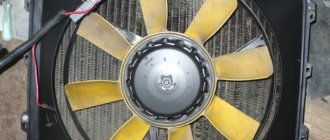
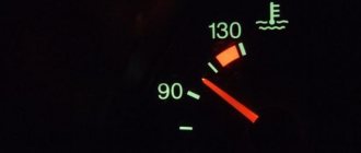
Hi all! Summer is approaching and I noticed that they are boiling, overheating, etc. I don’t like that in hot weather when driving not fast, the temperature of the engine coolant on the dashboard rises close to the red zone, after which the cooling system fan starts and the arrow falls down. And so back and forth. In general, for a VAZ 2110 such spasmodic behavior of the needle is considered normal.
Of course, the dashboard may be lying here and according to the On-Board Computer the readings are completely different. But still the effect is unpleasant and always alarming. I would like to somehow make the temperature control smooth and not abrupt. So that the temperature is maintained at the same level all the time due to different rotation speeds of the Carlson or by turning on the fan earlier.
And then the idea occurred to me to make, like many others, a forced button to turn on the fan. After looking on the Internet how this is done, I got to work.
And so, what we need: 1. Copper wire with a cross-section of 1.5-2 mm. (I have a wire about half a meter long) 2. Button (I took the air circulation button.) 3. 2 terminals (male, female) 4. Electrical tape.
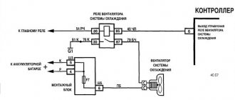
First of all, disconnect the “-” terminal from the battery. Next, we unscrew the cover, which is attached to two or three self-tapping screws, remove the cover and see three relays there.
We need a relay
fan,
Relay: 1 – electric fan relay; 2 – electric fuel pump relay; 3 – main relay (ignition relay).
ATTENTION! I have the order of the relays from the factory. The order of relays and fuses can be arbitrary, we focus on the color of the wires.
Next, we take the wire and connect contacts 30 and 87 on the fan relay, no matter which wire goes where, the contact numbers are on the relay itself. I have an upper and lower entrance. And we lead the wire to the place where you want to connect the button.
I got it like this:
fan switch button for VAZ 2110
I connected the battery, turned on the button, it works like a clock!
In addition, I made a video.
Thank you all, this is temporary for me and then I will connect it through an additional relay.
Everything is simple and clear, I think you won’t have any questions when connecting, the main thing is not to be lazy and everything will work out for you!
Many people have noticed that the temperature at which the radiator fan on a VAZ turns on is too high when compared with the operating temperature of the engine. Manufacturers are trying to reduce the amount of harmful emissions, since at high temperatures the fuel burns better together with the components.
But there is not only a positive effect, but also a negative one. If the engine overheats a little, then destructive processes begin for the metal inside, so wear resistance decreases. If you do not take into account that electrical components that affect the switched on fan may fail, then the time to notice overheating will be less than at normal temperatures.
We need to ensure that the engine operates evenly. This can be accomplished by creating a parallel fan circuit. A positive wire must be connected to one contact, and the negative contact is connected to the switch via a parallel wire.
It is worth mentioning additional features that allow you to control the normal engine temperature. There are no relays in the electrical circuit as a simple switch is sufficient for operation.
This method is not a replacement for the standard fan operation circuit, but only an alternative option for operating the unit at low temperatures. The driver must control the entire process.
If the car’s engine overheats, but this connection diagram is implemented, then it is better to check the cooling system again, ensuring its operation.
As soon as signs of overheating are detected, that is, the arrow indicating the temperature has entered the red zone, but there is still no puff of steam from the engine compartment, then turn on the interior heater at full power.
This will help reduce the temperature of the coolant in the cooling system. Next you need to turn on the emergency lights, depress the clutch pedal and roll to the side of the road. The car cannot be turned off immediately; the engine is run at normal idle speed for about five minutes, and the heater must still operate at full power. Only now can you open the hood and inspect the engine compartment.
You need to try to determine where the steam is coming from, see if there is coolant in the expansion tank, check the integrity of the thermostat, radiator and rubber hoses.
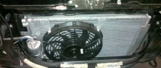
And so hello everyone. In Volgograd, the heat is terrible, the temperature in the shade is 40 degrees, and in the sun it’s probably 50 degrees, my engine cooling system can’t cope with such climatic conditions, even at speed the temperature doesn’t drop below 90, and in a traffic jam it actually reached almost 120. Start The fan of the engine cooling system (VSOD) is programmed at 105-107 degrees, shuts down somewhere around 100, constant on and off periodically begins to wear on. In connection with this, it was decided to modify the cooling system. There are many options for improvement: 1. Smooth start of the coolant fan 2. Use SILICH-BOREY 3. Start regulator for the RPV fan of LADA cars 4. Turn on the radiator fan (Carlson) from the button. I won’t describe each method, I chose 4 from the button, and I’ll tell you about it. And so we need:
1.relay 4-pin
2. block to the relay (optional)
3. resistance (resistor) of the heater VAZ 2110 3-pin
5. Terminals mother + father (10 pieces)
6.recirculation button VAZ 2110
And so everything is ready, we can start. We will use this circuit: The circuit is simple: in parallel with the standard fan relay Rv, an additional relay Rv2 is connected, manually controlled by the button Sv2. When relay Rb2 is turned on, the fan is connected to ground through resistance Rb2, which ensures slow rotation. The standard circuit operates as before; upon a signal from the controller, the fan turns on at full speed.
We are looking for a thin pink-black wire coming from the main relay (pin 85*) and a thick power white-black wire (pin 87) and connect our relay to them. * according to the book, on different VAZ models of the 10th family, the pink-black wire of the main relay can come to both pin 86 and 85. We focus on the color of the wires. We do not touch the black-purple (black-red) thin wire coming from the controller.
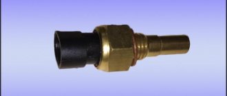
Design and testing of the VAZ 2110 fan switch sensor
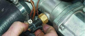
To maintain optimal temperature conditions of the car engine, a cooling system is designed. Its main elements are channels for antifreeze in the cylinder block, pipes, a thermostat, a radiator, and the electrical part includes a VAZ 2110 fan switch sensor, a temperature sensor and an electric motor with an impeller for cooling the radiator. Late detection of cooling system defects can lead to engine overheating and costly repairs.
Fan switch sensor LS 0108 (TM-108)
Expansion tank cap
The last reason why the VAZ-2110 cooling fan does not work may be a malfunction of the expansion tank cap. The fact is that when the engine is running, a pressure above atmospheric pressure is created in the cooling system, due to which the water, which is part of the coolant, does not boil at 100 ° C. The expansion tank cap valve is designed to maintain the required pressure. If it fails, the pressure in the system will be equal to atmospheric pressure. This will cause the coolant to begin to boil already at 100 degrees. A sensor designed to turn on at a higher temperature will naturally not work.
It is unlikely that you will be able to check the operation of the cover at home, so if during a visual inspection you have doubts about its functionality, it is better to replace it immediately.
Connection schemes
In VAZ 2110 injection and carburetor engines, the TM-108 bimetallic temperature sensor is used in different ways to control turning the fan motor on and off.
For carburetor engines it is located on the radiator on the left in the direction of travel. When the threaded part located directly in the coolant is heated, the bimetallic plate bends and closes the contacts. The voltage from the battery is supplied through a fuse to one contact of the electric motor, the second, when the sensor is triggered, is connected to the housing, setting the impeller in motion.
Fan switching sensor (carburetor VAZ 2110)
For VAZ 2110 and TM-108 injectors, it is located near the thermostat, the signal is sent to the electronic control unit (ECU). The control signal from the ECU is sent to the cooling system fan relay, which, similar to the sensor of a carburetor engine, controls the electric motor.
All engines have another device in the cylinder block, the signal of which is used to indicate the coolant temperature on the panel in the cabin.
MB types
It is worth noting that the pinout of fuses for the VAZ “Ten” is somewhat different, depending on the revision. The location of the backup protection relay varies greatly.
Version 3722010
Version 3722010 01
Version 3722010 08
The fan does not turn on
There may be several reasons for this:
- Fuse. In the mounting block, fuse F7, rated 20 amperes, may be faulty - it is responsible for powering the electric fan and sound signal circuits;
- Thermostat. The liquid circulates only in a small circle, the radiator and sensor do not heat up, and accordingly, the fan does not turn on. You can check by simply probing the pipes; those connecting to the radiator should begin to warm up after opening the thermostat;
- Sensor. For a VAZ 2110 with a carburetor, the contacts are closed for testing; if the device malfunctions, the electric fan will turn on. The connector of the injection motor must be disconnected; with the remaining elements working, the ECU will detect a break in the circuit and issue a constant alarm signal to the relay, which will forcibly turn on the electric motor for cooling;
- Cooling system fan relay for VAZ 2110 injection engines. The sensor is turned off and the power contacts on the relay located in the additional fuse box are closed. If everything works, then we check the control winding: on one contact there is always a positive from the main relay, connecting the second to the body, we try to hear the operation click. But it’s better to simply replace the relay for testing, temporarily, with a known good one;
- Electric motor. During testing, the connector is disconnected; to force the impeller to turn on, voltage is supplied directly from the battery.
No compression
Does the car start and stall or not start at all? This may happen if the engine lacks compression. Compression in an engine is the ability to maintain the pressure that is created in the combustion chamber when the piston rises to its highest dead center. Compression is measured with a special device - a compression meter. Whether you need such a diagnosis can be determined by external signs. Blue smoke from the exhaust pipe, unstable engine operation or idle speed does not stand still - these are all reasons for weak compression. Such an engine will consume more oil and fuel. If you put your hand on the exhaust pipe and small drops of oil remain on your hand, then this is another symptom of engine failure. It is best to contact specialists. After all, the cause could be a burnt-out piston.
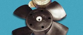
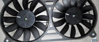
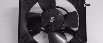
HOW TO REPLACE
If you are convinced that the cause of the malfunction lies in the fan motor, then the easiest way to carry out repairs is to completely replace the device. In this case, there is no point in spending money on a new casing. It will be cheaper to just buy a new electric motor.
Necessary tool
No special tool is needed. The work is carried out simply using 8 and 10 socket wrenches and a Phillips screwdriver.
Step-by-step algorithm of work
You can replace the cooling fan motor without removing the radiator.
- Disconnect the connector and device wiring harness from the casing.
- Unscrew the mounting bolts using a 10mm wrench.
- Unscrew the lower fastening nut.
- Using a 10 mm socket wrench, unscrew the mounting nut from the radiator.
- Using a size 8 socket wrench, unscrew the two pressure plate nuts.
- Remove the plate.
- Remove the electric fan along with the casing.
- Let's start dismantling the electric motor. Using a 10 mm wrench, unscrew the three mounting nuts and remove the engine along with the blades.
- Using a screwdriver, pry up the lock washer.
- And take it off.
- Remove the impeller.
- Put the impeller on the new motor. Make sure that the shaft pin fits into the impeller groove.
- Reassemble in reverse order.
Recommendations for care and maintenance
- Buy original fuses. Domestic or foreign, it doesn’t matter;
- Install strictly in accordance with amperage ratings. Unacceptable with lower or higher current strength. In the first case, this will lead to damage to the module, in the second - to breakdown of the unit, which is attached to the fuse;
- Carefully check the quality of fixation of terminals and limit switches on the board. If loose, tighten and press with pliers. A spark can cause a fire and melting occurs;
- If moisture gets in or condensation forms inside the mounting block, remove the cover, dry it, and if necessary, blow it with a stream of compressed air.
Carry out preventive and diagnostic work in the fuse box with the battery terminals removed in order to prevent a short circuit in the circuit.
The average service life of fuses is 40 – 60 thousand km. The service life of foreign analogues is 10–15% longer. Before replacing, read the instructions and get advice from service station specialists.
Sources
- zapchasti.expert/predoxraniteli/predoxraniteli-vaz-2115.html
- 7vaz.ru/vaz-2114/ne-rabotaet-ventilyator-na-vaz-2114-2115-2113.html
Main unit
The main block with fuses and relays is located in the cabin, on the left side, under the control panel. To access, press the latch switch.
Photo - diagram Option 1
Scheme Option 2
Scheme Option 3
Description of fuses
p, blockquote 15,0,0,0,0 —>
| F1 | 5A Lamps for license plate lights. Instrument lighting lamps. Side light indicator lamp. Trunk light. Left side marker lamps |
| F2 | 7.5A Left headlight (low beam) |
| F3 | 10A Left headlight (high beam) |
| F4 | 10A Right fog lamp |
| F5 | 30A Electric motors for glass door lifts |
| F6 | 15A Portable lamp |
| F7 | 20A Electric motor of the engine cooling system fan. Sound signal |
| F8 | 20A Rear window heating element. Relay (contacts) for turning on the heated rear window |
| F9 | 20A Recirculation valve. Windshield, rear window and headlight cleaners and washers. Relay (coil) for turning on the rear window heating |
| F10 | 20A Reserve |
| F11 | 5A Starboard side marker lamps |
| F12 | 7.5A Right headlight (low beam) |
| F13 | 10A Right headlight (high beam). High beam warning lamp |
| F14 | 10A Left fog lamp |
| F15 | 20A Electric seat heating. Trunk lock lock |
| F16 | 10A Relay - turn signal and hazard warning light switch (in hazard warning mode). Hazard warning lamp |
| F17 | 7.5A Interior lighting lamp. Individual backlight lamp. Ignition switch illumination lamp. Stop lamps. Clock (or trip computer) |
| F18 | 25A Glove box lighting lamp. Heater controller. Cigarette lighter. |
| F19 | 10A Door locking. Relay for monitoring the health of brake light lamps and side lights. Direction indicators with warning lamps. Reversing lamps. Generator excitation winding. On-board control system display unit. Instrument cluster. Clock (or trip computer) |
| F20 | 7.5A Rear fog lamps |
Fuse number 18 at 25A is responsible for the operation of the cigarette lighter.
The fog lamp fuse is installed separately in the instrument panel niche behind the main unit.
Relay purpose
p, blockquote 19,0,0,0,0 —>
- K1 - lamp health monitoring relay
- K2 - windshield wiper relay
- KZ - relay-breaker for direction indicators and hazard warning lights
- K4 - relay for low beam headlights
- K5 - headlight high beam relay
- K6 - additional relay
- K7 - rear window heating relay
- K8 - rear fog lamp relay
What devices in a car are fuses responsible for?
As can be seen in the diagram, the fuse block for the VAZ-2111 consists of twenty devices.
- F1 (current – 5 Amperes) – protects the network with all the car’s backlight lamps (dashboard – size indicator, trunk, license plates, left side lights);
- F2 (7.5 A) – low beam lights (left);
- F3 (10 A) – high beam lights (left);
- F4 (10 A) – fog light (right);
- F5 (30 A) – for power windows;
- F6 (15 A) – insert for cigarette lighter and carrying lamp;
- F7 (20 A) – sound signal and radiator fan;
- F8 (20 A) – heated glass (rear);
- F9 (20 A) – windshield cleaner and washer;
- F10 (20 A) – spare cell;
- F11 (5 A) – dimensions (right);
- F12 (7.5 A) – low beam lights (right);
- F13 (10 A) – high beam lights (right);
- F14 (10 A) – fog light (left);
- F15 (20 A) – for heated seats;
- F16 (10 A) – direction indicators and hazard warning lights;
- F17 (7.5 A) – lights in the cabin, near the ignition key and brake lights;
- F18 (25 A) – lighting in the glove compartment, cigarette lighter and interior heating;
- F19 (10 A) – checking the serviceability of the brake lights and reversing warning light;
- F20 (7.5 A) – fog lights (rear).
Interpretation of fuses and relays of injection models
The main electrical fuse module 2114-3722010-60 is located under the front engine compartment. This arrangement allows for quick access to all electrical systems of the car.
Block location
Please note that the location of the electrical fuse module may depend on the type of equipment and year of manufacture of the vehicle. As a rule, this is the upper right part of the engine compartment, under the front windshield. The mounting block is made of plastic in the form of a rectangular box. To protect against accidental opening, the box is equipped with special latches. To open the module, you need to snap off the two protective brackets and lift the top plastic protection. Under the cover are all the main control relays and electrical fuses of the vehicle.
To quickly remove the fuse, special plastic pliers are located on the plastic protection cover. With their help, you can very easily get any element. You need to grab the top edge of the plastic case with pliers and carefully lift the element.
For the convenience of the user, on the top plastic cover there is a complete diagram, made in the form of a schematic image, which shows all the electrical fuses and relays indicating the current strength (A).
Fuse and relay diagram for injection models
Table 1. Explanation of fuses and relays 2114-3722010-60
Modern fuses vary in color depending on the number of amps.
- 5A – brown
- 10A – red
- 15A – blue
- 20A – yellow
- 30A – green
The color distinction is made for ease of use and identification of the right fuse with the right resistance. There are also fuses available in black, grey, purple, white, orange and other colors. They all differ in the number of amperes that are registered on each product.
In each block, the manufacturer provides additional electrical fuses. They are designed to allow quick replacement of a burnt-out element. They are located at the bottom of the module and are marked with the names F17, F18, F19, F20. Each replacement element differs in color and number of amps.
If one of the electrical appliances in a vehicle breaks down, it is recommended that you first check the mounting block. To determine the burnt element, you need to completely turn off the engine and remove the key from the ignition. Using special pliers, carefully remove the burnt out module. Hold it up to the light and check for damage to the circuit. It is permissible to use fuses with a higher number of amperes, but only for a short time.