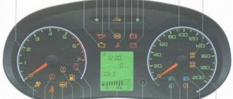
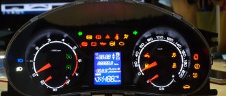
The VAZ dashboard has an electronic combination, as well as conveniently located backlighting. The lamps are illuminated from the inside, which is a feature of the 14th Lada.
Thanks to the instrument panel, the driver knows all the information he needs, what is the reserve and consumption of gasoline, mileage, etc. The panel should be easy to operate with a clear overview of the icons, scale, gauge and indicators.
What is the state of the automobile systems responsible for road safety, driving speed, the rest of the way to the intended object, rational engine operation and gasoline consumption, the operation of the suspension and electrical equipment - all this should be reflected on the control panel.
Signal lamps and equipment control devices must be required on the panel. There are a total of 19 symbols on the panel.
Control panel design
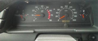
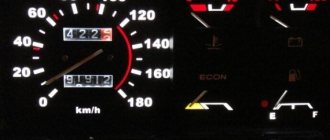
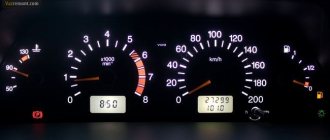
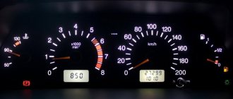
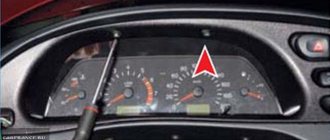
The main symbols include the fuel level, speedometer, tachometer, and sensors for cooling the liquid. The temperature sensor is indicated by an arrow on the left side of the panel.
If the sensor needle is in the zone from 105 to 130 degrees, you should immediately stop the car and wait until the engine cools down, otherwise the engine will simply boil. The tachometer is presented in the form of a dial scale on the instrument panel.
Engine speeds from 2 to 5.5 thousand per minute are considered the norm. If the needle falls into the red zone, fuel consumption may increase sharply, and the load on engine parts will become greater. The panel must have a speedometer.
With its help, the driver controls the speed, which directly affects road safety. The speedometer is an important part and should show clear data.
The sensor is located in the form of an arrow, which shows the fuel level in the car tank and is usually located on the right side of the device. Although it will not measure exact data about gasoline, you can find out the approximate fuel remaining at any time.
The panel design is quite simple, and at the same time highly informative; removing it is not difficult.
Using the panel, you can get a lot of useful information, namely: - is the condition of the VAZ safe at the time of movement - what is the speed, revolutions, availability of gasoline - what is the condition of the car's spare parts - other information, date and time.
With the help of sensors and meters, the driver is aware of all the information about his car. The VAZ tidy is made of plastic, which gives it an aesthetic appearance; it does not creak at all, unlike the same nine.
The device is simple, easy to disassemble and assemble.
Why is oil leaking from under the sensor?
The sensor is in direct contact with the oil, and when the sensor ages, its sealing ring, which is installed between the sensor and the cylinder head housing, becomes dented and begins to leak oil, which leads to fogging around the sensor or even to excessive oil leakage from under the sensor.
It is also quite common to see oil leaking through the sensor connector. For both reasons, it is recommended to replace the sensor with a new one.
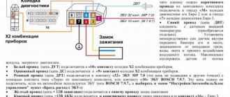
VAZ 2114 instrument panel pinout
Electrical connection diagram for the VAZ 2114 instrument panel (Click on the picture to enlarge)
- – rear window heating switch;
- – rear fog lamp switch;
- – switch for headlights and direction indicators;
- – mounting block;
- – windshield wiper switch;
- – fog light switch;
- – display unit of the on-board control system;
- – block of the instrument panel harness to the additional harness;
- – instrument cluster;
- – instrument panel harness connector to the on-board computer harness;
- – block of the instrument panel harness to the ignition system harness;
- – block of the instrument panel harness to the side door harness;
- – fuse 16 A;
- – fuse 16 A;
- – ignition switch;
- – lighting switch;
- – heater electric motor;
- – additional resistance of the heater electric motor;
- – ignition switch unloading relay;
- – rear fog lights relay;
- - starter relay;
- – socket for connecting a portable lamp;
- – cigarette lighter;
- – block of the instrument panel harness to the wiring harness of the glove box lighting lamp;
- – illuminator;
- – illuminator;
- – illuminator;
- – heater switch;
- – instrument lighting regulator with rheostat;
- – brake signal switch;
- – horn switch;
- – hazard warning switch;
- – backlight lamp for the heater control panel;
- – fuse 16 A;
- – seat heating relay;
The panel pinout is a diagram, but the diagram described in words seems easier for many. The contacts located on the instrument panel, and there are only 26 of them, are responsible for the operation of the indicators on the panel itself.
If a plus is applied, then each of the contacts shows information and the state in which the car is currently located. The panel is equipped with sensors and signal indicators, and the panel is controlled using an electronic unit.
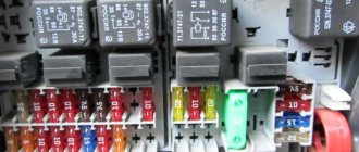
Inside the panel there are two pads - red and white. Fuses, inputs and outputs, controllers are connected to a specific plug. If the sensors fail, they need to be replaced.
You can check the serviceability of the wiring by disassembling the instrument panel. Oxidized or damaged wires must be replaced. Indicator lights may fail. Burnt out light bulbs must be replaced with new ones.
A faulty lamp sensor must also be replaced. The contact between the board and the lamp must be well connected, otherwise the ends of the contacts should be cleaned, bent, and if necessary, replace the lamp socket.
If the backlight stops working or the radio is faulty, the fuse must be replaced. Maybe the damage is not in the fuse, but in the wiring, which also requires replacement.
A short circuit in the fuse can also damage it.
Instrument cluster VDO 2115
The instrument cluster VDO 2115 is designed for installation in a VAZ 2115 car. It can also be installed in other VAZ cars with some modification of the instrument panel and in the presence of a special adapter cable.
Product operation
The operation of the combination is completely identical to the operation of the VDO 2110 instrument cluster, but there are a number of additional functions:
- built-in clock with liquid crystal display;
- built-in liquid crystal display of outside air temperature with ice warning function.
Controls
The only control is a push-button handle:
- Press once for 1 second. leads to switching the temperature display mode to the clock and vice versa;
- long press for more than 3 seconds. resets the daily mileage counter.
Pinout of combination VDO 2115 and correspondence of contacts with combination 21083 (high panel)
Contact 2110, 2115 Circuit Contact 21083
| 1b | Frame | 7k |
| 2b | Low voltage tachometer input | No |
| 3b | High voltage tachometer input | 3k |
| 4b | Ignition terminal 30 | 12 volt |
| 5 B | Coolant temperature sensor | 13b |
| 6b | General light switch | 8b |
| 7b | Carburetor damper | 10k |
| 8b | CHECK ENGINE terminal | |
| 9b | CHECK ENGINE terminal | |
| 10b | Ignition terminal 15 | 4b, 2k |
| 11b | Parking brake | 8k |
| 12b | Generator terminal 61 | 12b |
| 13b | Emergency oil pressure sensor | 12k |
| 1 to | To temperature sensor | No |
| 2k | To temperature sensor | No |
| 3k | Frame | 7k |
| 4k | Lighting combination | 4k |
| 5k | Right turn indicator | 13k |
| 6k | Left turn indicator | 5 B |
| 7k | Brake fluid level sensor | 7 BSK |
| 8k | To the on-board computer | No |
| 9k | Speed sensor | No |
| 10k | Terminal T fuel level sensor | 11b |
| 11k | high beam switch | 9b |
| 12k | Hazard switch | No |
| 13k | Ignition terminal 50 | 2 BSC |
1 way
Adapter diagram for connecting the VDO2115 combination instead of 21083
Method 2
The procedure for reconnecting connector terminals:
- 5b - 6k
- 9b - 11k
- 11b (red-rose) - remove
- 4b - 10b
- 8b - 6b
- 13b - 5b
- 2k - wire to pin. 3 temperature sensors
- 3k - 3b
- 7k - 3k
- 8k - 11b
- 10k - 7b
- 12k - 13b
- 13k – 5k
- red-rose — 10k
- 2BSK - 13k
- 7BSK - 7k
- 9BSK - 12k
- 3BSK - 2k + wires to pin. 1 speed sensor and a black temperature sensor
- wire with terminal from black-blue alarm wires on 4b
- wire with terminal from the blue terminal of the temperature sensor at 1k
- wire with terminal from pin. 2 speed sensors at 9k
Addition: switch the black wire from the brake fluid level sensor to the red-blue wire of the diagnostic block (+12V)
2.06.2002
Source: https://www.autoelectric.ru/auto/vaz/vdo/vdo2115.htm
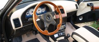
Tuning the dashboard of Lada 2114
To make their car distinctive, many motorists resort to tuning.
Although this is a troublesome task, it is worth it. Everyone strives to make the salon spectacular and cozy. The dashboard is a favorite place for tuning.
Backlight tuning
To make the panel devices look stylish and modern, they can be modernized. Let's look at how backlight tuning is done.
You can improve the appearance of a vehicle yourself, since the process is not at all complicated.
Everything you need for tuning:
- panel disassembly;
- removing the shield;
- tune the necessary parts;
- put in place.
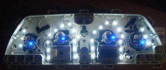
The first step is to replace regular yellow light bulbs with bright LEDs. Chinese diodes are cheaper, but they will not last long. To ensure that the light comes directly from the diodes, heat shrink is put on them, and the arrows will be clearly visible even in the dark.
The diode wires are connected to the backlight from the machine stove. To change the color of the arrows, a red diode is placed under each arrow. The light from the arrows will acquire a rich, bright red color, which will noticeably update the panel.
Blue light bulbs are popular. The central panel is also subject to tuning, respect is guaranteed. The glow becomes soft and irritates the eyes when driving.
Europanel
To give a modern aesthetic look, you can install a europanel.
The material of the panel is soft, rich, and less noisy. The original warning lamps and odometer make the panel modern and fashionable. It is equipped with many signal sensors. A special feature of the Europanel are sensor signals and airbags. White-blue LEDs also look beautiful. Typically, up to 50 LEDs are needed for tuning. If the glow of the diodes is very bright, then you can try to adjust it. Some VAZ components have this capability.
You can also tint the instrument panel, which will also look great. Improving the panel offers ample opportunities for creativity among car enthusiasts and designers. As a tuning option, you can install a start button, which will give the interior a distinctive style and modernity.
By the way, if the modernization will be carried out with your own hands, in order to avoid problems with the traffic police, you need to write a statement about the planned changes in the design of the car and wait for permission from the traffic police. After making changes, you need to undergo a technical inspection, where appropriate changes will be made to the registration documents.
Instrument panel lighting
The role of illumination on the panel is performed by incandescent lamps located at the top of the panel. Even higher, there is a green filter. The standard backlight color can be changed to a beautiful LED color.
To do this, you will need three LEDs, cartridges for them, foil and tape. The green filter can be removed altogether, or replaced with a different color.
And if you put a white LED on top of the filter, the glow will become brighter and more beautiful. The service life of the battery will become noticeably longer if you replace incandescent lamps with diodes. Installing LEDs is easy.
Handle the arrows with care; they are very fragile. To dismantle the console, remove the arrows, glass, tab, and select the lamps. A total of 28 light bulbs are taken, 5 red, the rest - optional.
The top of the lamps must be filed with a file to ensure the correct direction of the light. Solder a resistor to each LED. To the red diodes - a resistance of 1.5 Ohms, to the rest - 1.1 Ohms.
A piece of plastic is taken, a form is cut to size for installing new lamps, holes are made on the form for installing new light bulbs.
The tracks with output to the power supply are soldered on the back side of the form. You can change the backlight of LCD screens in the same way. At the end of the work, connect the power and assemble the panel.
You can also change the backlighting of the buttons on the power windows.
If desired, the backlight can be installed in the gearshift lever handle, in the glove compartment.
To replace the backlight of the LCD screen, the plastic base is removed along with the bulb. The soldering method can replace the backlight of the indicators.
It is important to know that uninterrupted operation of LEDs is only possible if the connection polarity is observed. By the way, in this way, everything in the car will not rattle, which often happens in VAZs.
As an option, you can put a red LED under each arrow and put heat shrink on top of the shield so that the glow is direct. As a result, the backlight will become rich red. Illumination of instrument scales is done in the same way.
In fact, backlighting is important when driving at night, and being able to see your instrument panel clearly in the dark is very important.
Self-test of the sensor
Even in garage conditions it is possible to check the specified element. When the engine starts, the red lamp lights up for a certain time and then turns off. If the warning light continues to work, it is worth checking the lubricant level in the motor. If the level is normal, you should check the element.
Useful : How much oil is poured into the VAZ 2114 engine?
There are several options for conducting diagnostics in a garage:
- Check the condition of the oil filter. A filter element clogged with dirt prevents the lubricant from flowing normally into the engine. Replacing the filter along with the oil is the best option to correct the problem;
- Visual inspection of the mounting location of the part. The presence of smudges indicates the need to change the rubber sealing ring;
- Use a pressure gauge to check the system pressure. With the part unscrewed, install the pressure gauge and start the machine. An indicator of 0.65 atmospheres indicates normal operation of the motor and a malfunction of the sensor;
- Check the power cord connection. When driving over uneven surfaces, the terminals come off from many sensors in the “four”.
Also, if you have second-generation Samara cars, you can install a known working element. The part cannot be repaired, so if there are problems, it is replaced with a new one. Because It is located in an open and convenient place - it can be replaced in a matter of minutes.
At sub-zero temperatures, the first start of the engine may be accompanied by a situation where the pressure light is on for a few seconds longer than usual. This is normal, because... In cold weather, the oil pump needs more time to pump the system with thickened lubricant.
Complete instructions for removing the control panel
To remove the device correctly, follow the instructions below:
- Using a Phillips screwdriver, remove the three screws that secure the center console;
- remove the cover, the protrusion located at the bottom, remove the protrusion from the bracket;
- Using a nozzle, unscrew the five screws located in the console on the right and remove the screen;
- Disconnect the terminal with the (-) sign from the battery. If there is a radio receiver, you need to remove it, remove the plug from the shield;
- Disconnect the wires coming from the cigarette lighter, remove the cartridge;
- Using a narrow screwdriver, remove the handle from the levers;
- pull the handle towards the heating and fan switch;
- unscrew the two screws above the panel and the two located under it using a screwdriver;
- unscrew the screw located behind the panel;
- Also unscrew the two self-tapping screws securing the cover;
- disconnect the harness and wire connectors. To avoid confusion when installing the panels, you should mark the order in which they are connected;
- unscrew the fastening bolts;
- unscrew the two self-tapping screws, those that secure the bottom bracket using an 8 key;
- unscrew the self-tapping screw securing the light guide and remove it;
- Also unscrew the screws securing the heating unit;
- remove lamp sockets;
- after removing the external parts, remove the decorative insert;
- unscrew all nuts with a 21 key;
- hydrocorrector, remove its lamp;
- Unscrew the screws that are attached to the cross member on the left.
Finally, the panel itself is removed. The panel is assembled accordingly in the reverse order.
It is important to remember the sequence of actions if you are performing this procedure for the first time. When disassembling and assembling you need to be extremely careful and attentive.
Features of diagnostics
Before carrying out diagnostics, it is recommended to conduct a visual inspection of the device for damage to the controller housing, stains from fluid leaking from the motor and other changes. If oil traces are detected, you need to make sure that the malfunction is in the sensor; inspecting the power unit will help make sure of this. When consumables leak from the regulator, the cause of the problem is related to wear on the seal. And if oil dripping occurs from the terminal connectors, you cannot do without replacing the controller.
To more accurately determine malfunctions during the operation of the device, diagnostics using a voltmeter will help:
To do this, you will need a pit or overpass and follow the following instructions:
- unscrew the bolts securing the protective coating of the unit;
- dismantle the protection;
- if DDM is detected, start the engine;
- disconnect the power cord from the device;
- use a tester to diagnose the voltage (voltage norm is 12 volts).
If the voltage is low, the cause of the malfunction is the display unit or the contacts of the electrical circuit, as well as its break.
Pinout of the VAZ 2114 window lifter button
A broken window regulator on a car is not only a problem that deprives the driver and passengers of a comfortable ride.
And also an incident that can attract the attention of a traffic inspector for violation of traffic rules. Therefore, knowledge of the design features of a car can help the car owner in a variety of situations. This article provides information on how to pin out the power window button on a VAZ-2114, what may cause the mechanism to break down, and the basics for troubleshooting problems in this device.
Car modifications 2114
VAZ-21140 . Modification with an 8-valve injection engine VAZ-2111, 1.5 liters and 77 horsepower. Serial production from 2003 to 2007
VAZ-21144 . Modification with an 8-valve VAZ-21114 engine, 1.6 liters and 81.6 horsepower. Years of serial production: 2007-2013.
VAZ-211440 . Another modification released in 2007, it was equipped with a VAZ-11183 engine with a volume of 1.6 liters and a power of 82 horsepower. The car was discontinued in 2013.
VAZ-211440-24 . Released in 2009, a modification with an injection 16-valve VAZ-21124 engine with a volume of 1.6 liters and a power of 89.1 horsepower. Discontinued in 2013.
VAZ-211440-26 . Modification with a 16-valve injection engine VAZ-21126, which complies with the Euro-3 environmental standard, with a volume of 1.6 liters and a power of 98 hp. The car was produced from 2010 to 2013.
What causes mechanism failure?
The reasons why problems arise in the operation of the window regulator can be divided into two large groups:
- Mechanical.
- Electrical.
The most common ones are listed below:
- Changing the position of the glass or its distortion.
- Failure of guides.
- Drive wear.
- Violation of the integrity of the cables.
- Closing the circuit.
- Oxidation of contacts.
- Failure of functional elements, including the ESP button, the adjustment of which will require theoretical knowledge of pinouts.
You can entrust repairs or replacement of components to specialists or do it yourself.
Installation of an electric window regulator (ESP) on a VAZ-2114
The most popular window lift systems on the VAZ-2114 are rack and pinion types. Their connection is carried out according to the scheme described below.
- Disconnect the on-board power supply from the supply. To do this, remove the terminals from the battery, you can close one - the negative one.
- All the wires that come with the ESP on the VAZ-2114 are twisted together into a bundle.
- The mounting block is removed by unscrewing the screw that controls the position of the latch.
- A wiring harness is mounted into the block in place of the connector of the block.
- The door trim is removed.
- The ESP is installed, along with all the buttons and keys.
By the way, you can make a choice if you wish. Install the buttons and keys that control the window regulator either on the door panel or on the control unit. In the latter case, you will need an additional wire and knowledge of the theory of pinout of the ESP button.
Purchasing a sensor and subsequent installation
Sensor selection
Oil pressure sensors for the VAZ 2114 can be easily purchased at any store specializing in the sale of car parts. This meter is always on sale and is one of the inexpensive spare parts.
Inside a car engine there are elements between parts of which friction occurs. During operation, the elements are subjected to strong heating, which contributes to their gradual destruction and deformation.
To avoid premature wear of engine parts, it is necessary to pour oil inside it. This helps create a protective layer that reduces friction, thereby reducing wear on component parts. In this regard, the resources of the power unit are significantly increased.
Cleaning the contacts of the window lifter button on a VAZ-2114
If suddenly the power window button on a VAZ-2114 begins to jam or refuses to work at all, you need to take a number of measures to diagnose it and correct the problems.
- First, dismantle the button. To do this, use the tip of a knife or the tip of a flat screwdriver to pick out the edge of the part body. And then they remove it from the nest with their hands. Carefully remove the button along with the fastening chip and wires. If this is not done, then to find the nest you will have to remove the podium.
- The chip remains in the hole in the housing, and the button itself with clamps and contacts needs to be diagnosed and, if necessary, repaired.
- To do this, place the part on a clean, light, flat surface in a well-lit room.
- Use the tip of a flat-head screwdriver to open the button. On both sides, both parts of the device are connected with special “bee” latches. Alternately unlocking one by one, the button is divided into two parts.
- The top part is the contacts. She is dismissed.
- The lower part is the “brains”, among which there is an electronic board. Its dismantling is carried out only after marks are made on the body about its exact location.
The contacts are carefully bent at an angle of up to 90 degrees, after which they are cleaned. And then they move on to analyzing the correct order of connecting the contacts. To do this, it is important to understand the principle of pinout of the power window button.
Pinout of the VAZ-2114 window lifter button
If you look at both halves, into which the VAZ-2114 window lift button was disassembled, then two rows of contacts and sockets for them clearly appear. One has four elements, the other three. This missing contact is considered the starting point for the subsequent pinout of the VAZ-2114 window lifter button.
With half of the body facing towards you, the contacts are numbered. Each “tooth” corresponds to a wire of a different color.
- Yellow. It connects to the dimensions and serves as a “plus”.
- Black. You can connect it to the negative side of the battery or connect it to ground.
- Red. This is a nutritional plus. Can be connected to a battery. Then the VAZ-2114 window lifter will work both with the ignition on and not. If the driver wants to get a working mechanism only when the engine is started, it should be connected to a similar plus of another unit.
- Green. Output to window lift motor.
- Blue. Output to window lift motor. If the 4th and 5th nodes are swapped, the device will work. But instead of an up arrow, the glass will go down. And vice versa.
- The sixth and seventh ones are automatically connected by “mice” to black, that is, to ground. But some recommendations suggest that this action is not advisable. It is better to connect to the battery.
The fundamental difference between whether the contact is connected to a battery or to another source is that in the first option the mechanism will work even when the ignition is turned off. And the pinout in these cases is relative.
Ignition switch pinout for VAZ 2114
I was planning to install auto start and was faced with the fact that in the smart book the ignition switch circuit is not clear =( . I decided to share the circuit and pinout
Connection diagram of the ignition switch VAZ 2113 2114 2115
The vehicle is equipped with an ignition switch (lock) type 2110-3704005 or KZ-881.
The ignition switch is equipped with an anti-theft locking device, a lock to restart the starter when the engine is running, and an illuminated lock socket.
The locking rod of the anti-theft device extends when the key is removed from the lock (the key can only be removed in position “0”). When the key is turned from position “0” to position “I”, the locking rod is retracted inside the lock, contacts “30” and “15” of the ignition switch are closed.
When the key is turned to position “II”, voltage is also supplied to the starter relay. From this position, the key automatically returns to position “I” under the action of a spring. You can turn the key back to position “II” only after first turning it to position “0”.
The circuits that are closed at various key positions are shown in the table below. The ignition switch (lock) connection diagram is shown in the top figure.
Purpose and design of DDM
The main purpose of this sensor is to measure the pressure in the engine lubrication system and inform the driver that the pressure has dropped to critical values or is absent altogether.
The sensor itself does not have a complex structure and only has a valve, which, in the presence of pressure, opens the electrical contact, thereby turning off the power circuit for the oil pressure warning lamp.
When the pressure decreases or is completely absent, the lamp lights up and informs about malfunctions in the engine. The operation of the sensor can be observed with the engine stopped and the ignition on; when starting, the lamp should go out, which means that the sensor is working properly and the engine lubrication system has the necessary pressure to lubricate all parts of the internal combustion engine.
Wiring diagram for the ignition switch on VAZ-2113, 2114 and 2115
Wiring diagram for the ignition switch on VAZ-2113, 2114 and 2115
Pinout of the ignition switch VAZ-2113, 2114, 2115:
- comes +12V for the microphone of the sensor of the inserted key;
- the mass comes when the driver's door is open;
- +12V goes to the starter (pin 50);
- +12V goes out after turning on the ignition (pin 15);
- +12V goes out when the key is inserted to pin 5 of the BSK;
- comes +12V to illuminate the lock cylinder;
- +12V comes from the battery (pin 30);
- not used.
| Photo 1, pinout of the ignition switch of a VAZ 2114 | Photo 2, pinout of the ignition switch of the VAZ 2114 |
Sources
- natapku.ru/ustrojstvo/panel-priborov-vaz-2114.html
- autoschemes.rf/shemy/vaz/2113-14-15/151-shema-elektrooborudovaniya-avtomobilya-vaz-2115.html
- 2shemi.ru/raspinovka-pribornoj-paneli-vaz/
- galantmotors.ru/document/shema/2114/2114_scheme_panel.php
- drive2.ru/l/186644/
- galantmotors.ru/document/shema/2114/2114_zamok_zajiganiya.php
- drive2.ru/l/544700810253041946/
Mass air flow sensor (MAF)
The mass air flow sensor is located in the engine compartment of the VAZ 2114 and is one of the most recognizable car sensors. The mass air flow sensor is attached with two bolts to the air filter box. The mass air flow sensor is responsible for counting the air intake from the engine and transmits the readings to the above-mentioned ECU. The mass air flow sensor is directly related to the formation of the air-fuel mixture.
Signs of a DMRV malfunction:
- Deterioration of car dynamics;
- Increased fuel consumption;
- Floating speed at XX;
- When starting the internal combustion engine, you have to turn the starter for a long time;