The engine control unit
To process readings from all sensors and control the engine, a special “brain”, an electronic engine control unit, is used. This part is used to take readings from sensors and, based on these readings, adjusts the fuel mixture, etc. A part rarely fails, but its main enemy is moisture; when water gets into the ECU, oxidation forms in it, which can cause short circuits and damage to the unit.
How to check
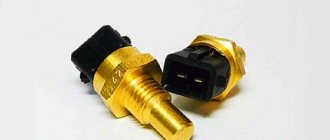
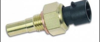
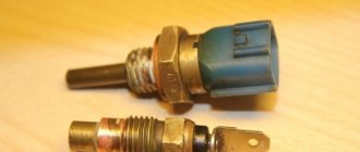
After removing the sensor, it should be visually inspected for damage or corrosion. The easiest way to check the DTOZH is to replace it with a known good one.
Required:
- multimeter (in voltmeter mode, ohmmeter with a measurement limit from 100 Ohm to 10 kOhm);
- thermometer (with a measurement limit of at least 100 °C);
- heat-resistant container with a volume of 0.5 l.
The procedure for checking the power supply circuit of the DTOZH:
- Switch the multimeter to voltmeter mode;
- Remove the block with wires from the sensor and turn on the ignition;
- Connect the negative probe of the multimeter to the engine ground, and the other to terminal No. 1 of the block;
- The voltage at the output must be at least 12 V.
If there is no voltage or they are less than 12 V, it means that the battery is discharged, the power circuit or the computer is faulty.
Procedure for checking DTOZH:
- Switch the multimeter to ohmmeter mode;
- Prepare a container with hot water (about 100 oC);
- Connect the multimeter probes to the sensor terminals and lower its working part into water;
- We measure the resistance of the DTOZH as the water cools.
The sensor resistance should be close to the data shown in the table:
| Coolant temperature, °C | DTOZh resistance, Ohm |
| 100 | 177 |
| 90 | 241 |
| 80 | 332 |
| 70 | 467 |
| 60 | 667 |
| 50 | 973 |
| 45 | 1188 |
| 40 | 1459 |
| 35 | 1802 |
| 30 | 2238 |
| 25 | 2796 |
| 20 | 3520 |
| 15 | 4450 |
| 10 | 5670 |
| 5 | 7280 |
| 0 | 9420 |
The verification process is also shown in the video:
If the DTOZH turns out to be in good order, the cause of the malfunction may be poor connector contact, broken wiring, or a faulty ECU.
Do not forget to change the antifreeze/antifreeze in the cooling system on time, and use the coolant recommended by the manufacturer.
Keywords: lada xray sensors | Lada Vesta sensors | Lada Largus sensors | Lada Granta sensors | Lada Kalina sensors | Lada Priora sensors | 4x4 sensors | cooling system lada xray | cooling system for Lada Vesta | cooling system for Lada Largus | cooling system for Lada Granta | cooling system for Lada Kalina | cooling system for Lada Priora | 4x4 cooling system | ECM Lada Vesta | ECM Lada XRAY | ECM Lada Largus | ECM Lada Granta | ECM Lada Kalina | ECM Lada Priora | ECM 4x4 | Niva sensors | Niva cooling system | esud niva | universal article
0 0 0 0 0 0
Share on social networks:
Coolant temperature sensor
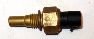
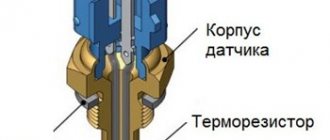
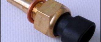
To adjust the fuel mixture depending on the coolant temperature and to automatically turn on the cooling fan in the Lada Largus car, a coolant temperature sensor (DTOZH) is used. The sensor is located near the thermostat and has a thermoelement inside it, which changes its resistance depending on the coolant temperature.
Signs of malfunction:
- The car does not start well when cold or hot;
- Increased fuel consumption;
- Black smoke from the chimney;
Replacement
The coolant temperature sensor is located in the thermostat housing; it is number 14 in the diagram.
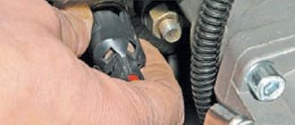
To change the DTOZH with your own hands, you should:
- Drain the coolant (car mechanics do not drain it);
- Disconnect the connector with wires;
- Unscrew the sensor (key “19”).
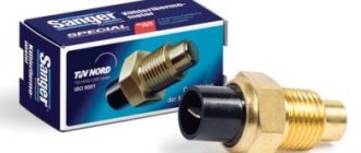
Installation is carried out in reverse order. To eliminate the leak, replace the copper washer or apply a heat-resistant sealant to the threaded part of the sensor.
Knock sensor
In all engines, due to differences in fuel quality, detonations can occur that can damage the engine if they are not eliminated in time. To capture and eliminate detonations in the Largus engine, a knock sensor is used, which detects them and sends signals to the ECU, which changes the ignition timing to reduce vibrations in the engine. The sensor is installed on the cylinder block in the middle, near the oil dipstick.
Signs of malfunction:
- Knock of “fingers” under load;
- High consumption;
- Loss of power;
Replacing and checking the coolant temperature sensor on LADA
The coolant temperature sensor (CTS) is one of the elements of the engine management system. Its purpose is to control the temperature of the fluid in the cooling system. Based on these data, the engine control unit adjusts the composition of the fuel-air mixture, crankshaft speed, and ignition timing.
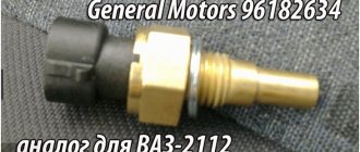
On all modern LADA cars (XRAY, Vesta, Largus, Granta, Kalina, Priora or Niva 4x4), replacing and checking the coolant temperature sensor is carried out in the same way.
Phase sensor
Many modern cars are equipped with phased fuel injection, which reduces fuel consumption and increases engine efficiency. Phased injection allows for the implementation of a phase sensor (camshaft sensor). The DF reads readings from the rotation of the camshaft pulley and transmits the readings to the ECU. The sensor operates based on the Hall effect. Installed near the intake camshaft pulley.
Signs of malfunction:
- High fuel consumption;
- Loss of traction;
Replacing the Lada Largus temperature sensor (VAZ Largus)
The engine is equipped with a distributed fuel injection system (each cylinder has a separate injector) with electronic control. The operating principles of the 1.6 (16V) and 1.6 (8V) engine control systems are almost the same. The main differences are the use of different ignition coils and different locations of individual system elements.
Elements of the electronic engine management system 1.6 (16V)
1 * – diagnostic block; 2 – absolute air pressure sensor; 3 – idle speed regulator; 4 – throttle position sensor; 5 * – control oxygen concentration sensor; 6 * – diagnostic oxygen concentration sensor; 7 * – control system malfunction indicator; 8 – electronic engine control unit; 9 – fuse and relay box in the engine compartment; 10 * – coolant temperature sensor; 11 * – crankshaft position sensor; 12 * – nozzles; 13 – ignition coils; 14 * – knock sensor; 15 – intake air temperature sensor.
*The item is not visible in the photo.
The engine control system consists of an electronic engine control unit (ECU), sensors for engine and vehicle operating parameters, as well as actuators.
Electronic engine control unit (ECU)
The ECU is the central unit of the engine control system. The unit is mounted on the rear wall of the battery platform. The ECU is a special-purpose mini-computer that consists of a random access memory device (RAM) and a programmable read-only memory device (PROM).
RAM is used for temporary storage of current information about engine operation (measured parameters) and calculated data. Codes of any faults that occur are also recorded in RAM. This memory is volatile, i.e. When the electrical power is interrupted (the battery is disconnected or the wiring harness is disconnected from the ECU), its contents are erased.
The PROM stores the engine control program, which contains a sequence of operating commands (algorithms) and calibration data (settings). The PROM determines the most important parameters of engine operation: the nature of the change in torque and power, fuel consumption, ignition timing, exhaust gas composition, etc. PROM is non-volatile, i.e. its contents do not change when the power is turned off.
Electronic engine management system diagram 1.6 (16V)
1 – battery; 2 – ignition switch; 3 – main relay; 4 – diagnostic oxygen concentration sensor; 5 – switching block; 6 – idle speed regulator; 7 – instrument cluster; 8 – air conditioner switching relay; 9 – control unit for heating, ventilation and air conditioning; 10 – refrigerant pressure sensor; 11 – power steering pressure sensor; 12 – absolute air pressure sensor; 13 – ignition coils; 14 – intake air temperature sensor; 15 – nozzles; 16 – air conditioning compressor; 17 – knock sensor; 18 – control oxygen concentration sensor; 19 – throttle position sensor; 20 – crankshaft position sensor; 21 – coolant temperature sensor; 22 – vehicle speed sensor (on a vehicle without ABS); 23 – high speed cooling fan relay; 24 – fan; 25 – low speed cooling fan relay; 26 – diagnostic connector; 27 – electronic engine control unit; 28 – power relay for the fuel pump and ignition coils; 29 – fuel module; 30 – solenoid valve for purge of the adsorber.
Elements of the electronic engine management system 1.6 (8V) (air filter removed for clarity)
1 – ignition coil; 2 * – diagnostic connector; 3 – nozzles; 4 * – knock sensor; 5 – idle speed regulator; 6 * – diagnostic oxygen concentration sensor; 7 – throttle position sensor; 8 – intake air temperature sensor; 9 – absolute air pressure sensor; 10 * – vehicle speed sensor (on a vehicle without ABS); 11 – electronic engine control unit; 12 * – control system malfunction indicator; 13 – fuse and relay box in the engine compartment; 14 – coolant temperature sensor; 15 * – crankshaft position sensor; 16 * – control oxygen concentration sensor; 17 * – spark plugs.
*Item not visible in photo.
Electronic engine management system diagram 1.6 (8V)
1 – battery; 2 – ignition switch; 3 – main relay; 4 – switching block; 5 – low speed cooling system fan relay; 6 – air conditioner switching relay; 7 – fan; 8 – high speed cooling system fan relay; 9 – control unit for heating, ventilation and air conditioning; 10 – instrument cluster; 11 – refrigerant pressure sensor; 12 – power steering fluid pressure sensor; 13 – control oxygen concentration sensor; 14 – diagnostic oxygen concentration sensor 15 – diagnostic connector (diagnostic block); 16 – electronic engine control unit; 17 – power relay for the fuel pump and ignition coil; 18 – fuel module; 19 – adsorber for the gasoline vapor recovery system; 20 – vehicle speed sensor (on a vehicle without ABS); 21 – knock sensor; 22 – absolute air pressure sensor; 23 – idle speed regulator; 24 – intake air temperature sensor; 25 – throttle position sensor; 26 – nozzle; 27 – crankshaft position sensor; 28 – ignition coil; 29 – coolant temperature sensor; 30 – spark plug; 31 – air conditioning compressor.
The ECU receives information from control system sensors, air conditioner refrigerant pressure switch and pressure sensor, power steering pressure sensor, and also controls actuators such as the fuel pump, injectors, ignition coils (coil-motor 1.6 (8V)), idle speed control , canister purge solenoid valve, cooling system electric fan, engine overheat indicator, air conditioning compressor electromagnetic clutch, and various system relays. When the ignition is turned on, the ECU issues a control signal to the main relay, and when the ignition is turned off, it delays turning off the main relay for the time necessary to prepare for the next turn on (to complete calculations, set the idle speed control, control the electric fan of the cooling system).
The ECU also performs diagnostic functions for the engine management system (on-board diagnostic system). The ECU detects the presence of a control system and stores fault codes in its memory. If a malfunction is detected, in order to avoid negative consequences (piston burnout due to detonation, damage to the catalytic converter in the event of misfire of the air-fuel mixture, exceeding the limit values for exhaust gas toxicity, etc.), the ECU turns on the malfunction indicator in the instrument cluster and switches the system to emergency mode. operating modes. Their essence is that if any sensor or its circuit fails, the ECU uses replacement data stored in the EPROM to control the engine.
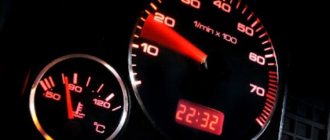
Engine management system malfunction indicator in the instrument cluster
The engine management system malfunction indicator is located in the instrument cluster. If the system is working properly, then when the ignition is turned on, the warning light comes on and then goes off - this way the ECU checks the serviceability of the on-board diagnostic system. Turning on the warning light while the engine is running informs that the on-board diagnostic system has detected a malfunction, and the vehicle continues to move in emergency mode. It is prohibited to operate a vehicle with a constantly lit or flashing warning light in the instrument cluster.
It is allowed to drive the car independently (in this case, some engine operating parameters may deteriorate - power, throttle response, efficiency) to a service station to eliminate the malfunction. If the malfunction is temporary, the ECU will turn off the warning light after 10 s, provided that there are no other fault codes in the unit’s memory that require turning on the warning light.
Diagnostic connector
Fault codes remain in the computer's memory and can be read using a diagnostic tool connected to the diagnostic connector (diagnostic block) located in the glove box.
Crankshaft position sensor
The crankshaft position sensor (CPS) is installed on the clutch housing, above the engine flywheel.
The sensor provides the computer with information about the speed and angular position of the crankshaft. The sensor is of the inductive type and reacts to the passage of the flywheel teeth near its core. The teeth are located on the disk at 6° intervals. To synchronize with TDC of the pistons of cylinders 1–4, one tooth out of 60 is cut off, which forms a cavity, and one tooth is double. When a double tooth and cavity pass past the sensor, a so-called “reference” synchronization pulse is generated in it. When the flywheel rotates, the magnetic flux in the sensor's magnetic circuit changes - alternating current voltage pulses are induced in its winding. Based on the number and frequency of these pulses, the ECU calculates the phase and duration of the pulses to control the injectors and ignition coil. If the DPKV or its circuits fail, the engine does not work.
Coolant temperature sensor
The coolant temperature sensor (DTOZH) of the 1.6 (16V) engine is screwed into the threaded hole of the thermostat housing located on the left end of the cylinder head. On a 1.6 (8V) engine, the sensor is screwed into the threaded hole in the left end of the cylinder head. The sensor provides information to the ECU, the coolant temperature gauge and the engine overheat indicator in the instrument cluster.
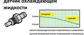
The sensor is a thermistor with a negative temperature coefficient, i.e. its resistance decreases with increasing temperature. The ECU supplies a stabilized voltage of +5 V to the sensor and, based on the voltage drop across the sensor, calculates the coolant temperature, the values of which are used in most engine management functions. If a malfunction of the sensor or its circuits occurs, the ECU turns on the cooling system fan to constant operation and calculates the temperature value using a bypass algorithm.
Throttle position sensor
The throttle position sensor (TPS) is installed on the axis of the throttle valve and is a potentiometric type sensor.
A stabilized voltage of +5 V is supplied to one end of its winding from the ECU, and the other is connected to the ECU ground. From the third terminal of the potentiometer (slider), the signal for the ECU is removed. By measuring the output voltage of the TPS signal, the ECU determines the current throttle position to calculate the ignition timing and duration of fuel injection pulses, as well as to control the idle air control.
If the sensor or its circuits fail, the ECU calculates the expected value of the throttle position based on the crankshaft speed and air flow.
Knock sensor
The knock sensor (DS) of the 1.6 (16V) engine is screwed into a threaded hole on the front wall of the cylinder block, located in the area between the 2nd and 3rd cylinders. On a 1.6 (8V) engine, the sensor is screwed into a threaded hole in the rear wall of the cylinder block in the area of the 3rd cylinder.
The piezoceramic sensing element of the sensor generates an AC voltage signal, the amplitude and frequency of which correspond to the vibration parameters of the engine. When detonation occurs, the amplitude of vibrations of a certain frequency increases. At the same time, to dampen detonation, the ECU adjusts the ignition timing.
Control oxygen concentration sensor
The control system uses two oxygen concentration sensors.
The control oxygen concentration sensor (UDCC) is installed in the threaded hole of the exhaust manifold.
The sensor is a galvanic current source, the output voltage of which depends on the oxygen concentration in the environment surrounding the sensor. The ECU calculates the duration of the fuel injection pulse based on parameters such as air flow, crankshaft speed, coolant temperature, and throttle position. Based on a signal from the UDCC about the presence of oxygen in the exhaust gases, the ECU adjusts the fuel supply to the injectors so that the composition of the exhaust gases is optimal for the efficient operation of the catalytic converter.
The oxygen contained in the exhaust gases, after entering into a chemical reaction with the sensor electrodes, creates a potential difference at the sensor output, varying from approximately 100 ± 100 mV to 800 ± 100 mV. A low signal level corresponds to a lean mixture (oxygen present), and a high signal level corresponds to a rich mixture (no oxygen).
When the UDCC is in a cold state, there is no output signal from the sensor, since its internal resistance in this state is very high - several megohms (the engine control system operates in an open loop). For normal operation, the oxygen concentration sensor must have a temperature of at least 300 °C, so for quick warm-up after starting the engine, it has a built-in heating element, which is controlled by the ECU. As the sensor warms up, the resistance of the sensor drops and it begins to generate an output signal.
The ECU constantly supplies a stabilized reference voltage to the sensor circuit. Until the sensor warms up, the ECU controls the injection system without taking into account the voltage on the sensor. As soon as the sensor warms up, the ECU turns off the heating of the sensor and begins to take into account the signal from the oxygen concentration sensor to control the fuel supply in closed loop mode.
The oxygen concentration sensor can be “poisoned” as a result of using leaded gasoline or using sealants containing high amounts of silicone (silicon compounds) with high volatility during engine assembly. Silicone fumes can enter the combustion chamber through the crankcase ventilation system. The presence of lead or silicon compounds in the exhaust gases can lead to sensor failure. If the sensor or its circuits fail, the ECU stores the corresponding fault code in its memory and controls the fuel supply in an open loop.
Diagnostic oxygen concentration sensor
The diagnostic oxygen concentration sensor (DOSC) is installed in the exhaust system pipe after the catalytic converter.
The functions of this sensor include diagnostics (assessment of the operating efficiency) of the catalytic converter and the implementation of a second, more accurate control of the enrichment of the air-fuel mixture (slow control system). The signal generated by the sensor indicates the presence of oxygen in the exhaust gases after the catalytic converter.
If the neutralizer is working normally, the readings of the diagnostic sensor will differ from the readings of the control sensor (at a constant vehicle speed, the voltage at the sensor terminals should change in the range of 600±100 mV, and when the movement slows down - below 200 mV). The operating principle of the diagnostic sensor is the same as the control oxygen concentration sensor, but the sensors are not interchangeable.
MAP sensor
The absolute air pressure (MAP) sensor for the 1.6 (16V) engine is installed in the receiver on the right. On a 1.6 (8V) engine, the sensor is installed in the intake manifold on the left.
The sensor contains a sensitive piezoelectric element and a load variable resistor. The ECU supplies a stabilized voltage of +5 V to the sensor resistor. The sensor piezoelement reacts to changes in pressure (vacuum) in the intake manifold and changes the reference voltage supplied to the load resistor. The ECU takes this change in voltage into account when calculating the amount of air entering the engine. If the sensor or its circuits fail, the ECU stores a fault code in its memory.
Intake air temperature sensor
The air temperature sensor (ATS) at the inlet of the 1.6 (16V) engine is installed in the front receiver. On a 1.6 (8V) engine, the sensor is installed in the intake manifold on the left.
The sensor is a negative temperature coefficient thermistor, meaning its resistance decreases as the temperature rises. The sensor changes its resistance depending on the air temperature in the intake manifold. The information received from the sensor is taken into account by the ECU when calculating the engine air consumption and to adjust the ignition timing. If the sensor or its circuits fail, the ECU stores a fault code in its memory.
Vehicle speed sensor
The vehicle speed sensor (VS) is used in the engine control system of a vehicle without ABS. The sensor is installed on top of the gearbox housing.
The sensor is driven by a gear mounted on the differential box. The operating principle of the speed sensor is based on the Hall effect. The sensor outputs rectangular voltage pulses to the ECU with a frequency proportional to the speed of rotation of the drive wheels. The number of sensor pulses is proportional to the distance traveled by the vehicle. The ECU determines the speed of the vehicle based on the pulse frequency. If the sensor or its circuits fail, the ECU stores a fault code in its memory.
On a car with ABS, there is no speed sensor, and in its place there is a plug installed in the gearbox. In this case, the ECU receives signals from the wheel speed sensors.
Engine ignition coil 1.6 (16V)
The ignition system is part of the engine management system.
The ignition system of the 1.6 (16V) engine consists of individual ignition coils and spark plugs for each cylinder. There are no high-voltage wires in the ignition system - the tip of the coil is placed directly on the spark plug.
Engine ignition coil 1.6 (8V)
The ignition system of the 1.6 (8V) engine consists of an ignition coil, high-voltage wires and spark plugs. The four-terminal ignition coil is a unit of two coils. The tips of high-voltage wires are connected to the terminals of the secondary windings of the coils. The current in the primary windings of the ignition coils is controlled by the ECU depending on the engine operating mode. The coils are powered sequentially in pairs. Thus, a spark simultaneously jumps in two cylinders (1–4 or 2–3) - in one at the end of the compression stroke (working spark), in the other at the end of the exhaust stroke (idle).
In operation, the ignition system does not require maintenance or adjustment, with the exception of replacing spark plugs. If the ignition coil or high-voltage wire of the 1.6 (8V) engine fails, they must be replaced.
Spark plug
Spark plugs with a noise suppression resistor with a resistance of 6 kOhm ± 1.5. The gap between the spark plug electrodes is 0.9–1.0 mm, the hexagon wrench size is 16 mm. The relays and fuses for the fuel injection system are located in a mounting block installed in the engine compartment.
Operation of the control system
When the ignition is turned on, the ECU activates the control system: it turns on the fuel pump to create the required pressure in the fuel rail and processes the signals from the coolant temperature and throttle position sensors to calculate the composition of the air-fuel mixture when starting the engine. If during this time the starter does not start cranking the crankshaft, the ECU turns off the fuel pump after 2 seconds and turns it on again after cranking starts.
When the engine is running, the ECU processes sensor information: crankshaft position, throttle position, coolant temperature, absolute air pressure, intake air temperature, vehicle speed (on a car without ABS), wheel speed (on a car with ABS), oxygen concentration . Depending on the engine operating mode, the ECU controls the operation of the injectors, ignition coils, idle air control, canister purge valve, and engine cooling system fan.
When the air conditioning is turned on, the ECU increases the engine idle speed and sends a signal to engage the air conditioning compressor clutch.
The ECU calculates the ignition timing depending on the engine speed, engine load and coolant temperature.
The composition of the mixture is regulated by the duration of the control pulse supplied to the injectors - the longer the pulse, the greater the fuel supply, and vice versa.
Under normal engine operating conditions, fuel is injected alternately into each cylinder at the start of the intake stroke. To do this, the ECU uses information from the crankshaft position sensor, which determines the TDC of the pistons of the 1st and 4th, as well as the 2nd and 3rd cylinders.
The system does not have a camshaft position sensor (phase sensor). Therefore, to determine which of the two cylinders needs to be injected, the ECU uses the following algorithm. Each time the engine is stopped, the last activated injector is recorded in the ECU memory, and when the engine is restarted, the command is first sent to this injector. If fuel is injected into the cylinder at a time other than the start of the intake stroke, the ECU starts a test program and determines the correct order of fuel injection into the cylinders.
If there is no signal from the crankshaft position sensor (the shaft does not rotate or the sensor and its circuits are faulty), the ECU turns off the fuel supply to the cylinders. The fuel supply is also switched off when the ignition is turned off, which prevents self-ignition of the mixture in the engine cylinders.
During engine braking (with the gear and clutch engaged), when the throttle valve is fully closed and the engine speed is high, fuel is not injected to reduce exhaust gas emissions.
When the voltage drops in the vehicle's on-board network, the ECU increases the time of energy accumulation in the ignition coils (to reliably ignite the combustible mixture) and the duration of the injection pulse (to compensate for the increase in the injector opening time). As the voltage in the on-board network increases, the time of energy accumulation in the ignition coils and the duration of the pulse supplied to the injectors decrease.
The ECU controls the activation of the electric cooling fan (via a relay) depending on the engine temperature, engine speed and air conditioning operation (if installed).
The electric fan of the cooling system turns on if the coolant temperature exceeds the permissible value.
Note:
When servicing and repairing the engine control system, always turn off the ignition (in some cases it is necessary to disconnect the wire terminal from the negative terminal of the battery).
When carrying out welding work on a vehicle, disconnect the engine control system wiring harnesses from the ECU. Before drying the car in a drying chamber (after painting), remove the ECU. With the engine running, do not disconnect or adjust the engine management system wiring harness connectors or the battery terminal wire terminals.
Do not start the engine if the terminals of the wires on the battery terminals and the tips of the “mass” wires on the engine are loose or dirty. The ECU contains electronic components that can be damaged by static electricity, so do not touch its terminals with your hands.
The article is missing:
- High-quality photos of repairs
Source: https://wiki.zr.ru/70-2_Largus
Source
- https://carpedia.club/view/5556
Oxygen sensor
To reduce harmful emissions into the environment, they began to use sensors that limit the car engine, namely harmful emissions. The limitation occurs by reducing the fuel mixture and creating permissible emissions in the environment. Installing an oxygen sensor made it possible to reduce fuel consumption in cars, but it affected the dynamics. The sensor is located in the exhaust manifold.
Signs of malfunction:
- Black smoke from the chimney;
- High fuel consumption;
Oil pressure sensor
To measure the oil pressure in the engine, an oil pressure sensor is used, which informs the driver of a loss of pressure. The sensor resembles a valve that opens when pressure is present and extinguishes the lamp; as soon as the pressure disappears, the sensor closes the contact and lights the warning lamp. The sensor is located on the cylinder head housing near the air corrugation.
Signs of malfunction:
- The oil pressure lamp lights up when there is pressure in the system;
Speed sensor
A cable was previously used to determine the speed of a car, but in modern cars mechanics have faded into the background and now there are more and more electronics in cars. Speed in Largus is measured by a special speed sensor, which is located in the gearbox housing.
Signs of malfunction:
- The speedometer does not work;
- EUR does not work;