The dashboard of any car is one of the main components of the electrical circuit, which serves to monitor the condition of the main components. Since order is practically the only unit with which the driver most often interacts visually, many car owners are thinking about improving it. How to set up the VAZ 2109 dashboard and what pinout of the control panel is read below.
Electrical diagram of instruments on the panel
In the VAZ 2109, electrical circuits are placed using a printed circuit board on a board, which is secured by springs with latches on the rear wall of the panel housing. Three groups of plugs can be divided into:
- BSK;
- lighting, dimensions;
- characteristics of the nodes.
The conditional numbering of the nests differs from the standard arrangement. The top plug is numbered 1, then the numbering continues down the right side, and the numbers continue at the top along the left side. BSK terminals have a horizontal position and are numbered from left to right, 2-5 top row, 6-9 bottom.
In instrument circuits with the European version of the torpedo and high, the connector blocks are located horizontally. If you look from the trunk, there are 13 lighting sockets at the top of the BSK, on the right, and operating indicators of the units on the left.
On-board control system
BSK was created on cars with a high modification of the torpedo and the Euro version. Helps monitor the condition of the brake pads and fluid levels in the components while driving. Level sensors are displayed on the panel:
- brake fluid;
- oils;
- coolant;
- washing.
In addition, there is a relay for monitoring the operating condition of the lamps and a sensor indicating the degree of wear of the linings on the brake pads. In normal condition, the indicators do not light up and do not attract attention.
All BSK lights come on when the ignition is turned on for a few seconds and go out. During movement, they begin to glow when the controlled element approaches a critical level, or rather the minimum level for the normal operation of a particular unit. Measures must be taken immediately, since there is no reserve for the signal from the dashboard lamp.
The on-board control system greatly simplifies vehicle maintenance, especially on long routes, and warns of a critical situation. But it does not exclude the need to check oil and brake fluid levels before leaving the garage, regular brake maintenance and changing the linings before they wear out.
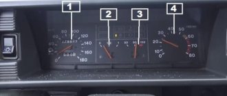
Main indicators
The VAZ 2109 has an instrument panel, an electrical circuit on the board, and has different color connectors for the output plugs. Sensors that are most important for safe movement and normal operation of the car are connected to red. These are indicators such as:
- fuel level in the tank;
- parking brake condition;
- carburetor choke position;
- emergency pressure in the system;
- battery charge level;
- fuel injection;
- tachometer.
The right turn indicator lamp and resistors are also connected to this group of connectors. In older models before 1995, VAZ 2109, the electrical circuit does not have BSK connectors, so the distribution of lamps is somewhat different and includes some lamps for emergency and control lights, brake fluid level and hazard warning lights.
Lighting fixtures and dimensions
The white connector of the output plugs is connected mainly to sensors that signal the operation of lighting devices, these are lamps:
- outdoor lighting;
- fog lights;
- dimensions;
- emergency lighting;
- high beam;
- turning indicators;
- stops;
- reverse speed headlights;
- heated rear window.
This group of sockets also includes the connection of such indicators as seat belts not fastened and injection toxicity adjustment, indicators for turning left turns on at the moment of starting to move.
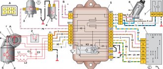
Full scheme
1 – block headlight; 2 – gear motor for headlight cleaner*; 3 – engine compartment lamp switch; 4 – sound signal; 5 – electric motor of the engine cooling system fan; 6 – fan motor activation sensor; 7 – generator; 8 – solenoid valve for turning on the headlight washers*; 9 – solenoid valve for turning on the rear window washer* (not installed on the VAZ-21099); 10 – solenoid valve for turning on the windshield washer; 11 – electric motor for glass washer; 12 – oil pressure warning lamp sensor; 13 – carburetor solenoid valve; 14 – carburetor limit switch; 15 – spark plugs; 16 – plug socket for a portable lamp; 17 – engine compartment lamp; 18 – ignition distributor sensor; 19 – carburetor solenoid valve control unit; 20 – windshield wiper gearmotor; 21 – switch; 22 – ignition coil; 23 – starter; 24 – top dead center sensor of the 1st cylinder**; 25 – diagnostic block**; 26 – starter activation relay; 27 – coolant temperature indicator sensor; 28 – reverse light switch; 29 – battery; 30 – brake fluid level sensor; 31 – mounting block; 32 – parking brake warning lamp switch; 33 – brake light switch; 34 – glove box lighting lamp; 35 – heater fan electric motor; 36 – additional resistor of the heater electric motor; 37 – heater fan switch; 38 – backlight lamp for heater levers; 39 – cigarette lighter; 40 – rear window heating switch; 41 – rear fog light switch; 42 – fog light circuit fuse; 43 – alarm switch; 44 – external lighting switch; 45 – ignition relay; 46 – ignition switch; 47 – steering column switch; 48 – instrument lighting switch; 49 – side direction indicator; 50 – lamp switch on the front door pillar; 51 – lamp switch on the rear door pillar (not installed on VAZ-2108 and VAZ-21083); 52 – lampshade; 53 – sockets for connecting individual interior lighting to the lampshade; 54 – switch for the carburetor air damper warning lamp; 55 – turn signal indicator lamp; 56 – indicator lamp for external lighting; 57 – rear fog light indicator lamp; 58 – backup warning lamp; 59 – control lamp for high beam headlights; 60 – indicator lamp for heated rear window; 61 – speedometer; 62 – instrument cluster; 63 – instrument cluster lighting lamps; 64 – coolant temperature indicator; 65 – voltmeter; 66 – fuel level indicator with reserve indicator lamp; 67 – econometrician; 68 – “STOP” indicator lamp; 69 – battery charge indicator lamp; 70 – control lamp for the carburetor air damper; 71 – hazard warning lamp; 72 – brake fluid level warning lamp; 73 – parking brake warning lamp; 74 – oil pressure warning lamp; 75 – rear light; 76 – sensor for level indicator and fuel reserve; 77 – pads for connecting to the rear window heating element; 78 – license plate lights; 79 – rear window wiper gear motor* (not installed on VAZ-21099)
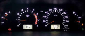
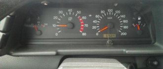
Travel speed
The speedometer is one of the most important indicators. In addition to the speed of movement, it also shows the distance traveled. On models produced before 1995, this is mainly only the total mileage value. Later models have a daily trip counter and a button that allows you to reset it.
If malfunctions occur in the speedometer, you should check the fastenings and condition of the flexible shaft. Pay attention to bends, the radius of which should be more than 10 mm. Replace the drive cable; if this does not help, then installing a new speedometer is required. The price of services in the salon for this repair is small, so it is better to immediately contact specialists.
The weak link in the electrical equipment of Lada
In a VAZ car, such repairs or replacement of the device are carried out as follows. All terminals are unscrewed and wires are removed. The nut that regulates the tension of the generator belt is loosened. Then the device moves away and the belt is removed. After unscrewing the bracket and the adjusting bar, the faulty generator is removed. A new device is installed in its place. Installation of a new generator is carried out in reverse order.
To avoid problems with recharging the battery in the future, this procedure should be repeated after the next ten thousand kilometers.
Electrical circuit repair
The VAZ 2109 power supply circuit is based on general connection principles. Plus goes from the battery to all devices. The minus for each is indicated separately, from the unit whose operation is signaled by a specific light bulb. Most breakdowns can be fixed with your own hands.
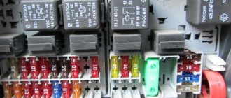
Any video will tell you that if several indicators fail to work, you should start by checking the serviceability of the fuses. Having opened the hood, you will see on the right under it a black box with a diagram of the location of each specific breaker. Select the correct fuse and replace.
Before starting repairs, remember that the instructions for working with electrical circuits, regardless of voltage and current, require turning off the power and discharging the existing capacitors. You shouldn't risk your health. Moreover, you can accidentally short the contacts and completely burn the entire board.
If the control lamps fail, check the fastening in the sockets, clean the contacts and tighten them, which oxidize over time, replace the lamps. Use a tester to make sure there is no broken wire.
Most often, malfunctions occur in the operation of fuel level readings. You should check the setting of the float, which may be knocked down, and the resistor winding responsible for the deflection of the needle. To do this, you need to dismantle the sensor, ring the circuit, making sure it is in good condition and integrity. Then adjust the limiter. All this is done after checking the suitability of the fuses.
If the fuel level indicator arrow constantly changes its position abruptly, the contact between the current collector and the resistor has weakened. In this case, it is best to replace the sensor itself, since correcting this deviation will not be effective.
Modifications of VAZ-2109
VAZ-2109 . The basic model, which was produced from 1987 to 1997, was equipped with a 1.3-liter VAZ-2108 carburetor engine with a capacity of 64 horsepower.
VAZ-21091 . Modification of a car with a derated VAZ-21081 engine, 1.1 liter and 54 horsepower. It was mass-produced from 1987 to 1997.
VAZ-21093 . Modification of a car with a VAZ-21083 carburetor engine, 1.5 liters and 73.4 horsepower. Serially produced from 1988 to 2006.
VAZ-21093i . Modification with a VAZ-2111-80 injection engine, 1.5 liters. the first prototype appeared in 1994, mass production began in November 1998.
VAZ 21093-22 . Model made specifically for the Finnish market. It features improved interior trim, pre-installed alloy wheels and a new dashboard. The car was equipped with a 1.5 liter injection engine. Produced from 1995 to 1998.
VAZ-210934 . An all-wheel drive SUV with a VAZ-21093 body placed on a Niva frame, on which the suspension, steering, engine, gearbox and transfer case from the same VAZ-2121 Niva model were already installed.
VAZ 2109-90 . A variant of the car, which was equipped with a compact two-section Wankel rotary piston engine with a volume of 654 cm3.
VAZ-21096 . Export modification of the VAZ-2109 for countries with left-hand traffic, the steering column was located on the right.
VAZ 21097 . Export modification of VAZ 21091 with right-hand drive.
VAZ 21098 . Another export modification, but this time the VAZ 21093 model with a right-hand steering column.
VAZ-2109 Carlota . A car produced from 1991 to 1996 in Belgium by Scaldia-Volga.
VAZ-21099 . The next independent car model, which is a modification of the “nine”. This car had a 4-door, 5-seater sedan body and a rear overhang extended by 200 mm.
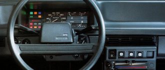
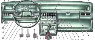
High instrument panel
According to the diagram presented below, the VAZ 2109 with a high panel has the following components.
High dashboard
Item number
What is this
Hazard switch
Windshield wiper and washer control lever
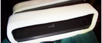
Central nozzles of the interior heating and ventilation system
On-board computer (not available on all trim levels)
Glove compartment lid (glove compartment)
Side nozzles of the interior heating and ventilation system
Speaker (loudspeaker) trim
Power window switches (available on certain trim levels)
Control panel for heating and interior ventilation system
Gearbox shift lever
Hand brake lever
Carburetor choke handle
Horn switch (horn)
Instrument panel light switch
Front seat heating switch (available as standard)
Rear fog light switch
Front fog lamp switch (not available on all trim levels)
Rear defogger switch
Hood lock drive lever
Turn signal and light control lever
Outdoor optics switch
Removal
Having familiarized themselves with the diagram of the high instrument panel of the VAZ 2109, many will probably think about the issue of removing it.
There are more than enough reasons to dismantle the panel:
- Repair, modernization of the heating system;
- Body repair;
- Replacing the old panel with a new one;
- Car painting;
- Body sound insulation, etc.
Dismantling process
This is not to say that removing the panel is a difficult process. The main problem is the time that needs to be spent on the work. The task requires concentration and increased attention in order to dismantle all elements, devices, and linings.
The process looks like this.
- Remove the steering wheel itself, otherwise it will seriously interfere with you when dismantling the panel.
- Pull the carburetor choke towards you. Injection engines do not have such an element. Then remove the plastic handle from the drive rod.
- Next, the decorative trim of the console is removed. To do this, simply unscrew the two mounting screws on the sides.
- Dismantle the ashtray and remove the cigarette lighter from its seat.
- Remove the handle that controls the speed of the fan motor.
- Using a screwdriver, pry the levers of the interior heater drive, which will allow you to remove these decorative elements.
- Disconnect the block with wires from the heater fan mode switch.
- Remove the two power wires for the backlight of the stove control panel from the contacts.
- Now you will need to get rid of several decorative control knobs - headlight hydraulic adjustment, instrument lighting control.
- The next step is to dismantle the hydraulic corrector itself and the lighting regulator. You will need a socket wrench that matches the diameter of the mounting nuts you are using. After unscrewing, push them inside. A little later you will be able to take them out.
- The air deflectors for heating the side windows are removed on the left and right.
- Here, using a Phillips screwdriver, you need to unscrew one mounting screw on each side that holds the upper panel covers.
- Remove the exterior light switch from the dashboard. To do this, you need to carefully pry the switch with a flat screwdriver and pull it out. Do not pull too hard as the switch is limited by the length of the wires used. Disconnect the power supply with the wires from the switch and set it aside. The block can still be pushed inside the panel.
- If you have an audio system, remove the radio. Now remove the standard socket from the radio. Of course, if you still have it.
- Unscrew the central fastener from the panel trim.
- Let's start by removing the dashboard trim. Before doing this, be sure to unlatch the latches located under the dashboard. This is done with a pair of flathead screwdrivers. Insert the tools along the edges and press down. By performing upward movements, the panel rises and then is completely removed.
- The cover has been removed, but that's only half the battle. Next, you can easily disconnect the power supply from the cigarette lighter and the cigarette lighter lamp.
- Also, without much difficulty, the wires from the alarm signal and the hazard warning lights are disconnected.
- Be sure to remember to remove the decorative trim from the front speaker and the heated glass switch, plus the rear fog light switch trim. If you also have a speaker, you will need to remove it.
- Reach through the hole under the speaker to disconnect the wiring harness from the fog light and rear window defroster switch.
- The instrument cluster is held on the panel by two mounting screws, which must be unscrewed. Pull it towards you, unscrew the nut and remove the flexible drive cable from the speedometer.
- That's it, the block with wiring from the instrument cluster can be disconnected and put aside for now.
- Do the same with the ignition switch - disconnect the block with wires, remove the ignition relay ground wire from the connector.
- Here, in close proximity, you will see a wire from the air damper warning lamp. But only for the carburetor VAZ 2109. Injection versions are not equipped with this wire.
- On each side of the panel, unscrew one bottom mounting screw.
- Disconnect the power supply wiring for the glove compartment lighting.
- Unscrew the heater panel fasteners and move it down. This way the panel will not disturb you.
- Remove the fasteners for the interior heater guide rod.
- Unscrew all the remaining side top and center fasteners, after which the panel can finally be completely removed.