The sensors are connected directly to the block, which is a computing module. The VAZ electrical circuit includes a sealed tank.
On carburetor and injection engines, it is imperative to pay attention to the wires that transmit high voltage to the spark plugs.
On a VAZ injector with 8 valves, the electrical circuit has exactly these features. VAZ 21099 Complete replacement of electrical wiring. How to celebrate Bodyworker's Day.
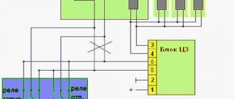
Relay for monitoring the health of brake light lamps and side lights.
Only after some time more modern injection versions appeared. They are necessary to power the sensor system, electric fuel pump, on-board computer and other components.
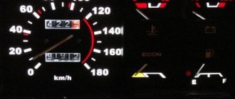
On-board control system display unit. Only the modification of the starter may differ.
Subsequently, the controller, based on the information coming from the on-board computer, makes a decision on the position and duration of opening of the injector damper. Instrument cluster.
How to connect motor wiring from brains
VAZ 2110 diagram
Colored wiring diagrams for the VAZ 2110 (injector and carburetor engine) are provided with a description of all elements for various modifications. The information is intended for self-repair of the car. Electrical circuits are divided into several blocks for ease of viewing via a computer or smartphone; there are also circuits in the form of a single picture with a description of the elements - for printing on a printer in one sheet.
There are two types of electrical wiring for the VAZ-2110: carburetor and injector. There are slight differences, but the basic principles of operation and wiring are the same. Depending on the location, the wiring differs into: under the hood and in the cabin. All electrical equipment of the car is connected using wires of a certain color. Each element has its own wiring harness through the blocks and fuses.
Carburetor engines
The very first VAZ-2110 cars, produced since the mid-nineties, were equipped only with engines with a carburetor injection system. Injection engines began to be installed at the beginning of the two thousandth. They are much better, they work more stable, but still many motorists still use cars with carburetor injection. Today they are not uncommon.
There are no significant differences in the electrical circuit between the injection and carburetor options. On carburetor “tens” the systems are almost the same as on injection ones. But you will definitely encounter a problem when replacing a carburetor with an injector. You will have to additionally lay several braids of electrical wiring. They are necessary to power the sensor system, electric fuel pump, on-board computer and other components.
VAZ 2110 - modifications
VAZ-21100 . The base model which was produced from 1996 to 2000. The car was equipped with an 8-valve carburetor VAZ-21083 engine with a displacement of 1.5 liters and a power of 69 horsepower.
VAZ-21101 . This modification has been produced since 2004, equipped with an 8-valve gasoline injection engine with a displacement of 1.6 liters.
VAZ-21102. Like the previous modification with an 8-valve injection engine, but with a volume of 1.5 liters.
VAZ-21103 . Modification of the “tens” with a 16-valve injection engine with a working volume of 1.5 liters.
VAZ-21103M . A restyled modification of the VAZ-21103, equipped with a 16-valve petrol injection engine with a displacement of 1.5 liters and a power of 92 horsepower. Produced since 2002.
VAZ-21104 . The modification is equipped with a 16-valve petrol injection engine with a working volume of 1.6 liters.
VAZ-21104M . A restyled modification of the VAZ-21104, equipped with a 16-valve petrol injection engine with a displacement of 1.6 liters. Produced since 2004.
VAZ-21106 GTI . The engine of the VAZ-21106 GTI is the most powerful and expensive modification that has been produced since 2000. The car was equipped with a 2-liter 16-valve Opel C20XE gasoline engine with a capacity of 150 horsepower. The car was fitted with a body kit with swollen arches, and the track was widened by 76 millimeters. It was equipped with R15 wheels with low-profile tires.
VAZ-21106 Coupe . Coupe VAZ-21106 in a coupe body. A distinctive feature of the car was the presence of only two doors, which were lengthened by 250 millimeters, while the body was shortened by 170 millimeters. The engine was installed the same as in the previous VAZ-21106 GTI model.
VAZ 21106 WTCC . A sports modification of the 106 model, it participated in the 2008 FIA WTCC international championship.
VAZ 21107 . Modification of a car for rally competitions. It was equipped with a welded safety cage and a different suspension design.
VAZ 21108 "Premier" . A modification with a body lengthened by 170 millimeters in the rear door area, which provided more convenient entry and exit of passengers. It was equipped with a 1.5-liter injection 16-valve engine.
VAZ 21109 “Consul” . 4-seater luxury limousine based on the VAZ-2110 car. In addition to the length of the body, the dimensions of the rear door were also increased, for more convenient entry and exit of passengers. Equipped with a 1.5 liter engine and R14 or R15 wheels. Overall dimensions: length - 4950 mm, width - 1700 mm, height - 1440 mm. Fuel consumption in the urban cycle is 9.5 liters per 100 kilometers.
VAZ 2110-91 . Modification of the VAZ-2110 with a 1308 cm3 rotary piston engine. The car could reach speeds of up to 240 km/h, and acceleration from 0 to 100 km/h took 6 seconds.
A car with a 16-valve injection engine in the Gran Lux configuration includes:
- Electric windows;
- Door locking;
- Trunk lock lock;
- Velvet seat upholstery;
- Immobilizer;
- Heated front seats;
- Ventilated 14-inch brake discs;
- Rear spoiler with additional brake light;
- Fog lights.
Heated seats and rear window
These two systems are very similar to each other, as they consist of the same components:
- Fuse to protect the circuit.
- Electromagnetic relay for switching a power circuit.
- Illuminated power button.
- Wire harnesses.
- Heating elements.
It is imperative to use electromagnetic relays. They are available in the electrical circuit for heated seats of the VAZ-2110. With their help, you can get rid of switching with a high current button.
As a result, the button on the dashboard switches only the low-current control circuits of the electromagnetic relay windings. The rear window heater has a similar design. If the car has heated rear view mirrors, then a similar scheme is used.
Wiring diagram for VAZ 2110 carburetor
In the instrument panel wiring harness, the second ends of the wires of white, black, orange, white with a red stripe and yellow with a blue stripe are connected to each other at the same points. The bends of the wires at the points of entry into the harness indicate the direction of their laying in the bundle.
See the complete diagram in one file below (click to enlarge):
1 – headlight 37 – instrument cluster 2 – front brake pad wear sensor 38 – rear fog light switch 3 – fan motor switch 39 – fog light indicator lamp 4 – engine cooling system fan electric motor 40 – rear window heating indicator lamp 5 – sound signal 41 – clock 6 – generator 42 – rear window heating switch 7 – oil level sensor 43 – steering column switch 8 – carburetor solenoid valve control unit 44 – block for switching wires when installing headlights of another type 9 – heater controller 45 – switch instrument lighting 10 – recirculation valve switch 46 – ignition switch 11 – illumination lamp for heater control levers 47 – connectors for connecting the headlight cleaner wiring harness 12 – switch 48 – socket for a portable lamp 13 – carburetor limit switch 49 – directional light 14 – control sensor oil pressure lamps 50 – brake light switch 15 – spark plugs 51 – interior lamp 16 – carburetor solenoid valve 52 – on-board control system unit 17 – coolant temperature indicator sensor 53 – fuel level indicator sensor 18 – ignition distributor 54 – hazard warning switch 19 – ignition coil 55 – driver’s seat belt sensor 20 – starter 56 – cigarette lighter 21 – heater fan motor 57 – ashtray backlight lamp 22 – additional resistor for heater motor 58 – glove compartment light switch 23 – speed sensor 59 – connector for on-board computer 24 – reverse light switch 60 – glove box lighting lamp 25 – micromotor gearbox for heater flap drive 61 – side turn signal 26 – recirculation valve 62 – switch in the front door pillar 27 – brake fluid level sensor 63 – switch in the rear door pillar 28 – pads for connecting the rear window washer motor 64 – parking brake warning lamp switch 29 – battery 65 – trunk light 30 – windshield washer motor 66 – interior air temperature sensor 31 – washer fluid level sensor 67 – external rear light 32 – level sensor coolant 68 – internal rear light 33 – windshield wiper motor 69 – license plate light 34 – mounting block 70 – block for connecting the rear window heating element 35 – blocks for connecting the warning light harness 71 – block for connecting an additional brake signal 36 – outdoor light switch
Interior heating system
The VAZ-2110 stove consists of a radiator, fan, and air duct system. Using a fan, the radiator is blown and air (hot) is supplied to special channels. The electrical circuit of the VAZ-2110 heater also includes a damper position regulator. In essence, this is a regular stepper motor.
It allows you to move the damper, changing the angle of its opening, as well as the amount of cold air entering the heater from outside. The blower fan electric motor is connected through a specially designed switch. It has several positions, each of which corresponds to a specific rotation speed.
The fan speed is adjusted using resistances installed in the heater housing. These resistances are included in the power supply circuit of the electric motor. Switching occurs using a regulator installed on the instrument panel. On older cars of the tenth family you can still find mechanical damper drives. Similar designs are also found on “nines” and “eights”.
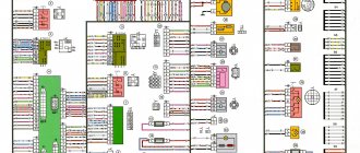
Diagram of VAZ 2110 injector 8 valves
1 – headlight 2 – front brake pad wear sensors 3 – horn 4 – cooling system fan 5 – reverse light switch 6 – battery 7 – generator 8 – oil pressure warning lamp sensor 9 – oil level sensor 10 – spark plugs 11 – injectors 12 – idle speed control 13 – electronic control unit blocks 14 – throttle position sensor 15 – crankshaft position sensor 16 – ignition module 17 – coolant temperature indicator sensor (for instrument cluster) 18 – starter 19 – diagnostic block 20 – coolant temperature sensor (for the engine management system) 21 – speed sensor 22 – fuel pump switch relay 23, 35, 39 – fuses 24 – electric fuel pump 25 – micromotor gearbox for heater damper drive 26 – recirculation valve 27 – heater fan 28 – windshield washer pump windows 29 – washer fluid level sensor 30 – brake fluid level sensor 31 – coolant level sensor 32 – windshield wiper gear motor
33 – additional heater fan resistor 34 – injection system power supply relay 36 – canister purge valve 37 – mass air flow sensor 38 – cooling system fan activation relay 40 – external lighting switch 41 – knock sensor VAZ-2110 injector 42 – oxygen concentration sensor ( heated lambda probe) 42* – CO potentiometer (installed on cars running on leaded gasoline; in this case, an oxygen concentration sensor is not installed) 43 – fog light indicator lamp 44 – rear window heating indicator lamp 45 – fog light switch 46 – rear window heating switch 47 – instrument cluster 48 – mounting block 49 – fuel level sensor 50 – ignition switch 51 – instrument backlight brightness control 52 – steering column switch 53 – heater control lever illumination lamp 54 – hazard warning switch 55 – electronic heater control unit; 56 – recirculation valve switch 57 – on-board control system display unit 58 – side direction indicators 59 – temperature sensor for the heating system 60 – interior lamp 61 – front interior lamp 62 – socket for a portable lamp 63 – electronic clock 64 – switches in the racks front doors 65 – switches in the rear door pillars 66 – glove compartment lighting lamp 67 – glove compartment lighting switch 68 – cigarette lighter 69 – ashtray lighting lamp 70 – brake light switch 71 – rear window heating element 72 – external rear lights 73 – internal rear lights 74 – license plate lamps 75 – trunk lighting lamp
See the complete diagram in one file below (click to enlarge):
Electric fuel pump drive
The electric fuel pump is powered through separate fuses and relays. It is installed under the rear seat directly in the tank. Moreover, it is combined with a gasoline indicator sensor. The main components of the electrical circuit of the VAZ-2110 pump:
- Electric motor driving the pump.
- Electromagnetic relay.
- Fuse.
- Wiring harness.
When the ignition is turned on, the electromagnetic relay is activated, after which power is supplied to the fuel pump.
Gasoline is pumped into the system to a certain pressure, after which the electric pump stops. A pressure sensor installed in the fuel rail sends a signal to the electronic control unit. It is by these parameters that the control system understands at what point it is necessary to turn on or turn off the fuel pump.
Diagram of VAZ 2110 injector 16 valves
1 - headlight 35 - instrument lighting switch 2 - front brake pad wear sensors 36 - ignition switch 3 - reverse light switch 37 - mounting block 4 - engine cooling fan electric motor 38 - recirculation valve switch 5 - sound signal 39 - controller heater 6 - right front door locking motor 40 - hazard warning switch 7 - power window relay 41 - heater control lever illumination lamp 8 - 8 A fuse 42 - glove compartment lighting lamp 9 - starter 43 - glove compartment lighting lamp switch 10 - battery 44 - cigarette lighter 11 - generator 45 - on-board control system display unit 12 - windshield washer motor 46 - ashtray lighting lamp 13 - washer fluid level sensor 47 - brake signal switch 14 - left front door locking motor 48 - locking motor left rear door 15 — power window switch of the left front door 49 — power window switch of the left rear door 16 — coolant level sensor 50 — power window motor of the left rear door 17 — windshield wiper motor 51 — socket for a portable lamp 18 — recirculation valve 52 — clock 19 - micromotor gearbox for heater flap drive 53 - gearmotor for electric window lift on the right rear door 20 - electric motor for heater 54 - power window switch at the right rear door 21 - trunk lock switch 55 - gearmotor for locking the right rear door 22 - power window switch at the right front door 56 - side turn signal 23 - electric window motor of the right front door 57 - parking brake warning lamp switch 24 - door lock system control unit 58 - driver's seat belt sensor 25 - additional heater motor resistor 59 - directional light bulb 26 - brake fluid level sensor 60 - interior light bulb 27 - electric window motor of the left front door 61 — interior air temperature sensor 28 — exterior lighting switch 62 — switch in the front door pillar 29 — instrument cluster 63 — switch in the rear door pillar 30 — rear fog light switch 64 — external rear light 31 — warning lamp fog light 65 - interior rear light 32 - rear window heating indicator light 66 - license plate lights 33 - rear window heating switch 67 - trunk light 34 - steering column switch A - blocks for connecting the rear window washer motor B - blocks for connecting the harness injection system C - to the warning light harness block D - block for connection to the on-board computer E - to the headlight cleaner harness block F - block for connection to the fuel level sensor in the electric fuel pump module G - to the rear window heating element H - block for connecting an additional signal braking J - to the trunk lock motor
Recent comments
- admin to the post differences between 8v and 16v controllers using the example of January 7.2 8v and Bosch 7.9.7 16v
- admin to post Useful information
- admin to post Atomic soft
- admin to the post Answered questions (comments) over the past months
- admin to the entry Pinout of the connection block SUD M7.9.7./January7.2 to the interior wiring of the Europanel (VAZ 2114)
- admin to the entry Chiptuning - About the table of monitoring stations and control centers (for dummies)
- admin to the post Answer to a question about Atomic Tune 2.8.8
- daser on Angel Eyes
- Kirill on the entry Pinout of the connection block SUD M7.9.7./January7.2 to the interior wiring of the Europanel (VAZ 2114)
- Anonymous to the post Answered questions (comments) in recent months
Electrical circuit of ECM VAZ-21101
1 — VAZ-21101 controller; 2 — block of the ignition system harness to the ABS cabin group harness; 3 — diagnostic block; 4 — immobilizer warning sensor; 5 — immobilizer control unit; 6 — ignition coil; 7 — spark plugs; 8 — nozzles; 9 — electric fuel pump; 10 — block of the ignition system harness to the fuel level sensor harness; 11 — block of the fuel level sensor harness to the ignition system harness; 12 — block of the ignition system harness to the injector harness; 13 — injector harness block to the ignition system harness; 14 — speed sensor; 15 — idle speed regulator; 16 — throttle position sensor; 17 — coolant temperature sensor; 18 — mass air flow sensor; 19 — oil pressure warning lamp sensor; 20 - phase sensor; 21 — oxygen sensor; 22 — crankshaft position sensor; 23 — knock sensor; 24 — solenoid valve for purge of the adsorber; 26 — coolant temperature indicator sensor; 27 — block of the ignition system harness to the instrument panel harness; 28 — block of the instrument panel harness to the ignition system harness; 29 — controller power supply fuse; 30 - ignition relay; 31 - ignition relay fuse; 32 — fuse for the electric fuel pump power supply circuit; 33 — electric fuel pump relay; 34 — electric fan relay; 35 — ignition system harness block to the air conditioner connector; 36 — block of the ignition system harness to the side door harness. 37 — electric fan of the cooling system; 38 — diagnostic connector; 39 — ignition switch; 40 — instrument cluster; 41 — on-board control system unit; 42 — starter relay; 43 — contacts of the 8-terminal blocks of the instrument panel harness and the front harness; 44 — contacts of the 21-terminal blocks of the instrument panel harness and the rear harness; 45 - trip computer.
- A - to the “plus” terminal of the battery;
- B1 — grounding point of the fuel level sensor harness;
- B2, B3 — grounding points of the ignition system harness;
- C - to the starter;
- D - to the driver's door interior lamp switch.
Prevention measures
If you notice that the electrical circuit of your ten is not working correctly, first of all you need to seek help from an electrician. Or you can independently diagnose high-voltage wires; for this you need to use a multimeter.
The diagnostic procedure is carried out as follows:
- First of all, the black wire must be installed in the left hole.
- The red cable should be installed in the middle.
- Next, the diagnostic device itself turns on. The multimeter must be activated in blue twenty mode.
- Now you need to carefully connect the multimeter probes to each other.
- If the arrow on the device display points to zero, that is, zero resistance, this indicates that everything is in order with the high-voltage wires. This means that the problem must be looked for elsewhere. If the multimeter needle on the dial points to one, this indicates that the resistance level is quite high and exceeds the norm. In this case, you can understand that the problem lies in a certain wire. Most likely it is interrupted or has poor contact. In order not to have to deal with repairs, the best option would be to purchase a new wire and install it.
When repairing wires, you need to use not only electrical tape, but also corrugated tape; it is more resistant to rubbing than electrical tape.
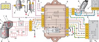
Engine control circuit VAZ-21102, 21103
Engine control circuit for VAZ-21102, VAZ-21103 (controller M1.5.4N, “January-5.1”).
1 - injectors 2 - spark plugs 3 - ignition module 4 - diagnostic block 5 - controller 6 - block connected to the instrument panel wiring harness 7 - main relay 8 - fuse connected to the main relay 9 - electric fan relay 10 - fuse connected to electric fan relay 11 – electric fuel pump relay 12 – fuse connected to the electric fuel pump relay 13 – mass air flow sensor 14 – throttle position sensor 15 – coolant temperature sensor 16 – idle speed regulator 17 – VAZ-21102 oxygen sensor 18 – knock sensor 19 – Crankshaft position sensor 20 – canister purge solenoid valve 21 – immobilizer control unit 22 – immobilizer status indicator 23 – vehicle speed sensor 24 – electric fuel pump with fuel level sensor 25 – oil pressure warning lamp sensor 26 – coolant temperature indicator sensor 27 – level sensor oil 28 - phase sensor (installed on a car with a 16-valve engine) A - block connected to the wiring harness of the anti-lock brake system (ABS) B - block connected to the air conditioner wiring harness C - block connected to the electric fan wiring harness D - wires , connected to the ignition switch (backlight lamp) E - block connected to the blue-white wires disconnected from the ignition switch (when installing the immobilizer) F - to the “+” terminal of the battery G1, G2 - grounding points The diagram uses the designation of the element number circuit to which this wire is connected, for example “-4-”. In some cases, in addition to the designation of the element number, it is given through an oblique fraction and the contact number, for example “-5/15-”. The diagram does not show the connection points of the pink-black, red and green with a red stripe wires.
Pinout of 8-pin connector
- power supply
- speed sensor (electric speedometer)
- fuel consumption (for BC)
- coolant sensor
- emergency oil pressure
- check lamp
- oil level sensor
- tachometer signal
How to look for faults?
In case of almost any breakdown in electrical wiring, the first step is to diagnose the contacts. To check their condition, you need to carefully inspect all the wires that are laid in the harness. You can do this in several ways:
- Visual inspection to determine integrity.
- Full inspection of the integrity of connections and their reliability.
- Checking the wires using a multimeter with the battery disconnected.
On carburetor and injection engines, it is imperative to pay attention to the wires that transmit high voltage to the spark plugs.
If they are damaged, the engine will run unstably. Signs of failure of high-voltage wires:
- Extraneous noise when the engine is running.
- The car may jerk while driving.
- Gasoline consumption increases.
- Unstable operation at low speeds.
Therefore, before sinning on any sensors, make sure that the high-voltage wires and the ignition module are in good condition.
Electrical circuit of ECM VAZ-21104
1 — block of the ignition coil wiring harness to the ignition system harness; 2 — block of the ignition system harness to the ignition coil wiring harness; 3 — ignition coils VAZ-21104; 4 — immobilizer warning sensor; 5 — immobilizer control unit; 6 — spark plugs; 7 — nozzles; 8 — diagnostic block; 9 — block of the ignition system harness to the ABS cabin group harness; 10 - controller; 11 — electric fuel pump; 12 — block of the ignition system harness to the fuel level sensor harness; 13 — block of the fuel level sensor harness to the ignition system harness; 14 — block of the ignition system harness to the injector harness; 15 — injector harness block to the ignition system harness; 16 — block of the ignition system harness to the side door harness; 17 — speed sensor; 18 — idle speed regulator; 19 — throttle position sensor; 20 — coolant temperature sensor; 21 — mass air flow sensor; 22 — oil pressure warning lamp sensor; 23 - phase sensor; 24 — oxygen sensor; 25 — crankshaft position sensor; 26 — knock sensor; 27 — solenoid valve for purge of the adsorber; 28 — oil level sensor; 29 — coolant temperature indicator sensor; 30 — block of the ignition system harness to the instrument panel harness; 31 — block of the instrument panel harness to the ignition system harness; 32 — ignition relay; 33 - ignition relay fuse; 34 — fuse for the electric fuel pump power supply circuit; 35 — electric fuel pump relay; 36 — electric fan relay; 37 — controller power supply fuse; 38 — ignition system harness block to the air conditioner connector; 39 — instrument cluster; 40 — ignition switch; 41 — electric fan of the cooling system; 42 — on-board control system unit; 43 — starter relay; 44 — contacts of the 8-terminal blocks of the instrument panel harness and the front harness; 45 — contacts of the 21-terminal blocks of the instrument panel harness and the rear harness; 46 — trip computer; 47 - diagnostic connector.
- A - to the “plus” terminal of the battery;
- B1 — grounding point of the ignition coil wiring harness;
- B2 — grounding point of the fuel level sensor harness;
- B3, B4 - grounding points of the ignition system harness;
- C - to the starter;
- D - to the driver's door interior lamp switch.
According to the scheme described above, fuel regulation in a car is carried out. Moreover, it depends not only on the load of the valves in the engine, but also on the corresponding position relative to the throttle valve. With the help of a diagram of electrical wiring and valves, it is possible to understand which of the relays or fuses is malfunctioning and replace it in time. In this case, one of the main roles when supplying fuel is played by electrical equipment (controllers) that regulates the operation of the injector.
Source
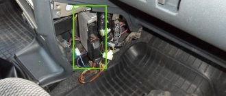
Starter connection
An electric starter is used to start the engine. It is a simple DC motor. The whole system works as follows:
- When the ignition is turned on, the rotor winding of the generator is energized, resulting in a constant magnetic field being created around it. This is a necessary condition for the operation of the generator set.
- As soon as the key is turned to the “Start” position, voltage is applied to the relay coil.
- Together with the retractor relay core, the gear and overrunning clutch move along the starter rotor. As a result, the gear meshes with the flywheel ring.
- At the same time, the core closes the power contacts inside the solenoid relay.
- Voltage is applied to the starter winding, the rotor begins to rotate and spins the engine crankshaft.
- The generator begins to produce current as the magnetic field rotates inside the stator winding.
Information that a motorist must know before replacing existing wiring
First of all, the car owner must know when and in what cases the car wiring is replaced. At the same time, it is also necessary to have information about the final operational life in order to objectively understand when the wiring may need to be replaced. List of the most common reasons that cause wiring to malfunction:
- the appearance of cracks in insulation during a long period of operation;
- oxidation;
- corrosion;
- fuse blown, etc.
Components needed to perform wiring replacement:
- multivariate set of wires;
- fuse block for VAZ 21104;
- housing for the heating system;
- various types of sensors: brake fluid, cooling system, etc.;
- pads;
- many terminals;
- Of course, it goes without saying, duct tape.
A practical look at rewiring
So, a detailed step-by-step algorithm for replacing the wiring:
- first you need to dismantle the front part of the cabin;
- then you can deal with the proper degree of isolation, if there is a desire for it;
- after which, you need to pay special attention to the front headlight switch;
- The windshield wiper (see Replacing windshield wipers on a VAZ 2110 on your own) operates using its own mini-motor, the wiring of which must be checked for serviceability, since very often it simply becomes acidified;
- understand all heating modes;
- the connection of all electronic devices must be carried out strictly sequentially, by increasing the number of connected wires.
Note. Before disconnecting all electronic devices, it is necessary to draw your own conventional electrical circuit by hand in order to correctly make the appropriate connections in the future.
- now it’s time to tackle the fuse blocks, or rather their installation;
- most wires exceed the required length, so they simply do not fit into the allotted space;
- the bracket is the most rational solution to the problem; it will allow you to successfully replace the fuses with new ones;
- with the installation of a new fuse, the position of the front light indicator light, as well as the emergency warning light, will change;
- the heater will also have to be affected: first you need to remove the old radiator and then disassemble it to make it possible to replace the fan;
- Assembly is carried out strictly in reverse order.
Note. Before you begin the wiring replacement procedure, you need to find its current diagram. Otherwise, during the process of assembly and disassembly, you can quickly get confused, and you will have to send the car to a car service center.
The main advantages of the new wiring:
- the emergence of a practical opportunity to connect any gadget;
- longer service life compared to old wiring;
- high degree of reliability of everyday functioning;
- improving the quality and stability of electronic devices and much more.
It is always necessary to remember that installing homemade wiring is an easily feasible technical manipulation; the main thing is to understand all the necessary nuances.
The main objective signs of a car wiring fault
So:
- the car engine does not start;
Note. If the essence of the malfunction lies in the ignition system, then one of the diagnostic signs is that the car will not start. Moreover, if the car starts poorly, but still starts, then problems with the wiring can be excluded from the list of possible causes.
- the central ignition lock has stopped functioning properly;
- the car’s electronics begin to function intermittently or do not work at all;
- headlights function intermittently or do not function at all;
- the characteristic smell of burnt rubber began to appear regularly in the car interior;
- the battery discharges too quickly, although it was functioning properly before;
- and of course, it goes without saying, multiple problems associated with the ignition system.
Practical example of wiring fault:
- the engine suddenly began to function with noticeable interruptions;
- at first glance it may seem that the essence of the problem lies in a malfunction of the ignition system;
- however, a motorist with sufficient experience will not be able to immediately determine where the essence of the malfunction lies, since the cause of an interruption in engine operation may be the ignition system, or a burnt-out spark plug as a result of a wiring fault.
The instructions for replacing the wiring yourself are extremely simple, and the diagnostic process, in principle, does not present any significant practical difficulty. It is recommended to use photo and video materials during the replacement process. The main thing is to find the root cause of the problem in the wiring system. It is never too late to modernize VAZ wiring, and this, in turn, will allow you to use almost any modern high-tech devices for your car. The price of replacing the wiring yourself is significantly lower than the corresponding service at a car service center.
Messages 1 to 20 of 24
1 Topic by kavamax 2013-03-30 20:05:52
- kavamax
- New member
- Inactive
- From: Chelyabinsk
- Registration: 2013-03-30
- Messages: 8 Thanks : 1
- Auto: 211002
Topic: Resolved: What is the best way to replace the ECU and wiring of a VAZ?
Hello, very good site, a lot is clear. My question is this. Or, more simply, did I go wrong? I became, so to speak, a victim of outbids. The story is like this. Based on many conversations and reviews when buying a car, everyone (friends, friends) said that they were the best cars in the area, which is what I did. I was going with my girlfriend to the city of Magnitogorsk from the city of Chelyabinsk to buy a car in the region of 83 thousand rubles. Of course, I expected bad things from this car for that amount, but nothing stopped me. Having visited all the markets there, and there are only two of them, the left bank and the right bank, and called all the sellers (direct owners), the choice fell on the VAZ 2110 1.5L. 8kl. (injector) 1998, the color according to the title is green (it looks like a tsunami or something else), in general it’s painted, well, everything is beautifully polished as always, I got under the bottom, it’s not rotten, I looked at the sills, they’re not rotten, the anthers have been changed (or rather, as it turns out, they’ve been rubbed with shoe polish ), but the most interesting thing awaited me 156 km from Chelyabinsk (two blows under the hood, white smoke from the clutch side), I dialed his phone in shock, saying that he is inhumane, etc. but he claims that everything worked, it’s my own fault. I called my friends and got me to Chelyabinsk, so I parked the car in the garage. Then I had to look for a new working cylinder block assembly (that block was hastily sealed, the antifreeze was combined with oil), my friend and I spent a week together. The cylinder block cost me 11,200 rubles. replacement of consumables: Shel oil 1400 RUR oil in G-box 1350 RUR armor wires elephant 400 RUR Bosch spark plugs 430 RUR air filter 150 RUR oil filter 130 RUR fuel filter 115 RUR antifreeze Felik 10L 700 RUR