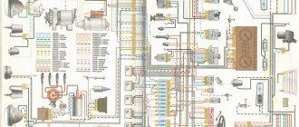
Wiring diagram for VAZ 2114 injector 8 valves with a detailed description of the electrical system, engine compartment wiring, fuses, harnesses and high-voltage wires. Wiring diagrams for VAZ 2114 injector 8 valves are presented in high-resolution color format for more detailed viewing.
Wiring diagram VAZ 2114 injector 8 valves
- Rear window heating switch;
- Rear fog lamp switch;
- Switch for headlights and direction indicators;
- Mounting block;
- Wiper switch;
- Fog light switch;
- On-board control system display unit;
- Instrument panel harness block to additional harness;
- Instrument cluster;
- Instrument panel harness connector to on-board computer harness;
- Instrument panel harness connector to ignition system harness;
- Instrument panel harness to side door harness;
- Fuse 16 A;
- Fuse 16 A;
- Ignition switch;
- Light switch;
- Heater motor;
- Additional resistance of the heater electric motor;
- Ignition switch relief relay;
- Rear fog light relay;
- Starter relay;
- Cartridge for connecting a portable lamp;
- Cigarette lighter;
- Instrument panel harness connector to glove compartment lamp wiring harness;
- Illuminator;
- Illuminator;
- Illuminator;
- Heater switch;
- Instrument lighting regulator with rheostat;
- Brake light switch;
- Horn switch;
- Hazard switch;
- Heater control panel backlight;
- Fuse 16 A;
- Seat heating relay;
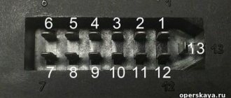
Ш1-Ш4 — mounting block connectors. X1, X2 - instrument panel harness connectors to the instrument cluster. A - grounding point of the instrument panel harness.
Underhood wiring diagram VAZ 2114 injector
Diagram of the underhood wiring of a VAZ 2114 injector and front harness connections with a detailed description of the electrical equipment, connection diagram, indicating the mounting block and connected devices.
- Starter;
- Rechargeable battery;
- Generator;
- Battery and starter harness pads and front harness;
- Mounting block;
- Sound signal;
- Coolant temperature indicator sensor;
- Washer fluid level sensor;
- Left headlight;
- Headlight right;
- Ambient temperature sensor;
- Reversing light switch;
- Engine electric fan;
- Front harness block to ignition system harness;
- The block is used on cars with a carburetor;
- Brake fluid level sensor;
- Oil level sensor;
- Coolant level sensor;
- Mounting block;
- Oil pressure warning light sensor;
- Rear window washer motor;
- Washer motor;
- Wiper motor;
Ш5-Ш8, Ш11 - mounting block connectors. A1, A2, B1, B2 - grounding points of the front harness.
Causes and troubleshooting
Let's look at the reasons why the starter on a VAZ-2114 does not turn.
The causes of the malfunction may lie not only in it, but also in other elements involved in the circuit.
POPULAR WITH READERS: Replacing the Lada Granta timing belt
Moreover, the behavior of the circuit itself when closed can tell you where to look for a breakdown.
The key is in the “start” position and the starter does not start.
If, after turning the key to the “start” position, the starter does not turn, but the solenoid relays are activated (a distinct click is heard, indicating that the armature has moved), and the lamps on the dashboard have noticeably dimmed, then the reason may be:
- In a discharged battery
. Electric consumers left turned on at night drain the battery and the amount of its energy is not enough to power the electric motor. Severe frosts can also affect the battery (exposure to sub-zero temperatures leads to an increase in resistance in the battery). To start a car you need to either charge the battery or “light” it from another car;
Wiring diagram VAZ 2114 injector - rear harness
Wiring diagram for VAZ 2114 fwafva injector
- Mounting block;
- Rear window heating element;
- Rear window wiper motor;
- License plate light;
- License plate light;
- Left side turn signal;
- Side turn signal right;
- Individual lighting lamp;
- Interior lamp;
- Handbrake sensor;
- Left lamp;
- Right lamp;
- Additional brake signal;
- Interior lamp switch;
- Interior lamp switch;
- Interior lamp switch;
- Interior lamp switch;
Oxygen sensor repair
Let's start with malfunctions of the oxygen sensor, and the VAZ 2114 wiring diagram for the injector will provide us with all possible assistance. If you don't know what the circuit is for, read this article. The most common causes of its breakdowns are a broken chain or the formation of carbon deposits on the working surface.
And the consequences that occur due to its breakdown look something like this:
- reduction in engine power;
- increased fuel consumption;
- failures during acceleration;
- tripling, etc.
It is not always easy to determine a possible malfunction in this sensor. The computer generates an error signal when there is a break in the circuit. But it may be the degree of his sensitivity.
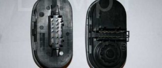
Tip: to make a conclusion about replacing the sensor, let's start by checking the power supplied to it. Open the hood and disconnect its connector located on the cooling pipe.
To check it yourself, we need a tester:
- Let’s connect its “minus” to the motor, and attach the positive terminal to contact “B”.
- When the ignition is turned on, the tester will output 12 volts, otherwise this will mean that the battery is discharged or there is a break in the power circuit.
- Another reason could be a malfunction of the control unit, which is immediately confirmed by the on-board computer.
Note! To determine whether the sensitivity has disappeared, you need to connect the positive contact to output “A” and the negative contact to “C”. If the voltage between the 2 contacts is 0.45 V, then the circuit is in order. Otherwise, there is a fault in the power circuit.
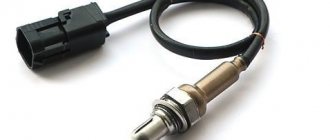
In order to accurately check your oxygen sensor (see photo), you will need to enrich or lean the fuel mixture while simultaneously measuring its indicators. In any case, the operation of the sensor should not exceed 100,000 kilometers, after which it should be changed in any case, since this will be associated with unnecessary fuel costs.
Sensor installation location
- If the computer indicates the following error as "low signal", it will mean that the mixture is too rich.
- If the signal level is high, then the mixture is too lean.
Note! These errors indicate the composition of the combustible mixture, but not the serviceability of the oxygen sensor itself. Analyze whether there are air leaks and measure the fuel pressure, but only then look at the sensor itself.
Replacement procedure
The instructions for replacing the regulator will not seem too complicated, especially if you use the tips below:
- it is necessary to place the car in a pit and remove the engine protection;
- disconnect the oxygen sensor, as described above, by disconnecting the connectors;
- remove the sensor with a wrench set to “22”.
Tip: if the sensor is too stuck, spray it with WD-40 from a bottle. You can heat the sensor and unscrew it while heated. Light tapping with a hammer may help.
The sensor is installed in the reverse order (see video). After tightening, the connector is connected. The sensor is fastened to the cooling system pipe with a clamp, after which protection can be installed.
Using the idle speed controller, automatic adjustment and stability of engine speed is maintained while the machine is stopped. It is based on a stepper electric motor equipped with a conical needle. Install it on top of the throttle body, near the throttle sensor. Attaches with a pair of screws.
As soon as you start the ignition, the rod extends and it rests against the calibration bell of the throttle pipe . The algorithm included in the operation of the sensor is designed to return the valve to its original state.
The electrical wiring of the VAZ 2114 works in such a way that a warm engine means that the regulator is located at a level in the range of 30-50 steps. Based on the location of the rod, the volume of air that enters through the calibration hole will also change.
As soon as the pitch decreases, the rod will retract. A single move can be up to 250 steps. If you need to replace the sensor and you purchase a new one, then do not forget to measure the distance between the flange and the rod head, which should be equal to 23 millimeters.
Wiring diagram VAZ 2114 injector - side door harness
Wiring diagram for side doors of VAZ 2114 with a detailed description of electrical connections, harnesses and electric locks.
- Side door wiring harness connector to instrument panel harness;
- Side door wiring harness connector to seat heating harness;
- Electric lock of the right rear door;
- Electric lock of the left rear door;
- Harness block to rear right loudspeaker;
- Harness block to rear left loudspeaker;
- Door lock control unit;
- Side door wiring harness connectors to the additional left harness;
- Side door wiring harness connectors to the additional left harness;
- Terminals of the side door wiring harness to the radio;
- Side door wiring harness block to the additional right harness;
A1 is the grounding point for the side door wiring harness.
General scheme
- — rear window heating switch;
- — rear fog lamp switch;
- — switch for headlights and direction indicators;
- — mounting block;
- — windshield wiper switch;
- — fog light switch;
- — display unit of the on-board control system;
- — block of the instrument panel harness to the additional harness;
- — instrument cluster;
- — instrument panel harness connector to the on-board computer harness;
- — block of the instrument panel harness to the ignition system harness;
- — block of the instrument panel harness to the side door harness;
- — fuse 16 A;
- — fuse 16 A;
- — ignition switch;
- — lighting switch;
- — heater electric motor;
- — additional resistance of the heater electric motor;
- — ignition switch unloading relay;
- — Rear fog lights relay;
- - starter relay;
- — socket for connecting a portable lamp;
- - cigarette lighter;
- — block of the instrument panel harness to the wiring harness of the glove box lighting lamp;
- — illuminator;
- — illuminator;
- — illuminator;
- — heater switch;
- — instrument lighting regulator with rheostat;
- — brake signal switch;
- - horn switch;
- - hazard warning switch;
- — backlight lamp for the heater control panel;
- — fuse 16 A;
- — seat heating relay;
Ш1-Ш4 — mounting block connectors. X1, X2 - instrument panel harness connectors to the instrument cluster. A - grounding point of the instrument panel harness.
Basic faults
If malfunctions occur with high-voltage explosive wires or wiring in general, this will be reflected in:
- on the functioning of the engine - the unit will not be able to operate at full power;
- on the functioning of the equipment;
- on the operation of optics and other systems.
In general, wiring faults are divided into several types - breakdowns of the ignition system and sensors. Depending on the type, the diagnostic procedure is determined. In order for the order to be correct, you first need to understand the type of malfunction.
Ignition failures
Signs of malfunctions in the injector control circuit, which will help determine the course of action:
- loss of engine power;
- the appearance of dips in power when you press the gas;
- unstable idle speed;
- incorrect operation of one or more cylinders.
The procedure for identifying a breakdown begins with diagnosing the presence of a spark in the explosive wires:
- the ignition is turned on;
- it is necessary to remove the tip from the explosive wire of the first cylinder;
- the tip must be brought close to the metal, but not pressed (the distance between the tip and the metal is about half a cm);
- then the starter turns on and you check if there is a spark, a similar operation is repeated with all the spark plugs (the author of the video is Home Auto Repair. Car Repair.).
If there is no spark, you need to look for problems in the coils or generator circuit, the procedure is as follows:
- the coil is diagnosed;
- module is checked;
- then you need to check the control unit.
In this case, the resistance is measured. A tester is used to diagnose coil resistance. You need to measure the resistance of the primary and secondary windings. The resistance level must be correct; if the resistance is incorrect, the windings may need to be replaced.
As for diagnosing the module, it is also done using a tester - you need to measure the resistance on the paired explosive wires. The resistance level should be 5.4 kOhm. If the resistance is different, then you have found the cause of the breakdown.
Sensor failures
As you know, cars of this model are equipped with multiple sensors, the failure of which can also cause unstable engine operation. Since wiring in the engine compartment can cause problems in the operation of the unit, you should try to move the pads and connectors before changing the sensors. Perhaps the problem is a poor connection.
Most regulators can be checked using a tester; as a rule, sensor failure is indicated by the Check lamp on the control panel. As for regulators such as idle speed and mass air flow, you can find out about their failure after diagnostics, which is carried out using the shutdown method. If the engine does not start at all, you need to check the crankshaft sensor.