Lada Priora cars are equipped with two oxygen concentration sensors (hereinafter referred to as OCC). The top one is diagnostic, the bottom one is control.
The controllers are designed to determine the quantitative composition of oxygen in the exhaust gases for the purpose of subsequent adjustment of the ignition angle.
An excess amount of air in the fuel mixture, as well as an insufficient amount, negatively affects the functionality of the technical device. Most often, fuel consumption increases, passive acceleration dynamics, and unstable idling.
During systematic operation of the machine, refueling with low-quality fuel, the controllers fail. The process of self-replacement is not complicated, but requires attentiveness on the part of the master. Violation of the regulations is not acceptable.
Oxygen sensor for Lada Priora: original, analogues, price, catalog numbers
Despite the fact that the price of the original controller is slightly higher than 1,500 rubles, not many car enthusiasts are willing to buy factory spare parts. Cheap analogues are often preferred.
So-called “fake devices” are installed instead of standard sensors. After 90 - 100 thousand km. The Lada Priora catalyst becomes unusable, as evidenced by a number of signs. At the request of the client, the service station technicians remove (cut out) the standard catalyst from the exhaust system and replace it with a “dummy”.
Dummy exhaust manifolds are made according to the scheme: 4-2-2 or 4-2. Popularly called spiders. This is a one-piece design together with the exhaust manifold coupling and exhaust pipe.
To prevent the electronic control unit from identifying a system error, the lambda probe is replaced with one of the following types of decoys:
- Mechanical;
- Electronic.
Lambda probe check.
To check the functionality of the oxygen sensor, you will need: factory instructions that will tell you where the lambda probe is located, an oscilloscope and a digital voltmeter. These are the main supporting tools. The engine should be warmed up while testing the device. How to check the lambda probe yourself? It's as simple as flushing the injector.
Study the manufacturer's instructions for the basic parameters of the oxygen sensor. Check the indicators that are affected by unstable operation of the lambda probe: on-board voltage, ignition timing, operation of the fuel supply system
Also pay attention to the appearance of the mechanisms, in particular the presence or absence of mechanical damage to the housing and wiring. Look in the engine compartment and find the lambda probe. Inspect it for external contamination
If the tip of the lambda probe is covered with a layer of soot, lead or a white-gray coating, then most likely it will need to be replaced. The damage to the device by deposits is caused by poor-quality fuel composition. If the probe tip is clean, continue checking further. Disconnect the oxygen sensor from the block and connect it to a digital voltmeter. Start the car and, by pressing the gas pedal, increase the engine speed to 2500 rpm. Using a device for enriching the fuel mixture, reduce the speed to 200 per minute. If your vehicle is equipped with an electronically controlled fuel system, remove the vacuum tube from the fuel pressure regulator. Look at the voltmeter reading. If the instrument needle approaches the 0.9 W mark, it means the lambda probe is in working condition. A malfunction of the sensor is indicated by the lack of response from the voltmeter, and its readings are less than 0.8 W. Do a lean mixture test. To do this, take a vacuum tube and provoke an air leak. If the oxygen sensor is working properly, the digital voltmeter reading will be at 0.2 W or lower. Check the operation of the lambda probe in dynamics. To do this, connect the sensor to the connector of the fuel supply system, and install a voltmeter parallel to it. Increase engine speed to 1500 rpm. The voltmeter readings with a working sensor should be at 0.5 W. Another value indicates a failure of the lambda probe.
Correct dismantling and installation of a new lambda probe sensor.
- First, disconnect the sensor wire from the electrical wiring. Carry out the procedure with a cold engine and the ignition off. To replace an old device, use a sensor with the same markings as the previous one.
- Using a suitable wrench, unscrew the old sensor. It is best to remove the device with the ignition on, and, accordingly, the hot sensor and fuel pipe, otherwise there is a risk of breaking the thread, since in a cold state the metal contracts and must be unscrewed with considerable effort. When steam appears from the holes, you can turn off the engine. It will be easier to unscrew further.
- Screw the new lambda probe as far as it will go to create a good seal.
- Connect the electrical wiring.
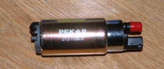
- Check the functionality of the new oxygen sensor using an oscilloscope, digital voltmeter, or ohmmeter at an engine temperature of 350 C.
You will learn how to repair the exhaust system in our other article.
Electric snag
The emulator has a microprocessor that corrects the signal for the ECU. The latter “believes” that the sensor is working and passes the data without interpreting it as an error.
In fact, there is no longer a catalyst in the design; instead, a section of the exhaust pipe is welded in.
The cost of the emulator varies from 1,500 rubles, which is 85–90% of the price of a new recreation center. Unlike a standard controller, the emulator has an unlimited service life.
| Catalog article/marking | Price in rubles |
| BOSCH 0 258 006 537 (8 and 16 valves) | From 1500 - 1600 |
| BOSCH 0 258 986 602 (8 and 16 valves) | From 1500 - 1600 |
| BREMI 30223 | From 1500 - 1600 |
| ERA 550489 | From 1500 - 1600 |
| DENSO DOX-0150 | From 1500 - 1600 |
| Metal spacer | 250-300 |
| Electronic emulator | From 1350 |
| *prices are as of May 2022 | |
Assignment of contacts of Bosch ME17.9.7 ECU
The table shows the assignment of contacts for controllers 21126 – 1411020-40, 11194 – 1411020-20. The difference in connection for controllers 21214 – 1411010-50 is highlighted in blue.
| № | Output purpose | № | Output purpose |
| Section X2 | Section X1 | ||
| 1 | Entrance. Crankshaft Position Sensor B | 1 | not connected |
| 2 | Entrance. Oxygen sensor 2 | 2 | not connected |
| 3 | Entrance. Other damper position sensor 1 | 3 | Weight of analog sensors |
| 4 | Weight of DC 1 | 4 | Weight of analog sensors |
| 5 | Weight of DTOZH | 5 | Accelerator pedal sensor 1 ground |
| 6 | Weight of DK 2 | 6 | Accelerator pedal sensor 2 ground |
| 7 | Weight of other damper position sensors | 7 | Refrigerant pressure sensor input (level 2) (not used) |
| 8 | Air flow sensor weight and temp. air | 8 | not connected |
| 9 | not connected | 9 | not connected |
| 10 | not connected | 10 | not connected |
| 11 | not connected | 11 | Accelerator pedal sensor 2 |
| 12 | not connected | 12 | not connected |
| 13 | Entrance. Crankshaft position sensor A | 13 | not connected |
| 14 | not connected | 14 | not connected |
| 15 | Entrance. DTOZH | 15 | Exit. Main relay |
| 16 | not connected | 16 | Entrance. Ignition switch terminal 15 |
| 17 | not connected | 17 | not connected |
| 18 | not connected | 18 | not connected |
| 19 | not connected | 19 | Entrance. Refrigerant pressure sensor (1 and 3) level (not used) |
| 20 | Entrance. Other damper position sensor 2 | 20 | not connected |
| 21 | not connected | 21 | Entrance. Accelerator pedal sensor 1 |
| 22 | not connected | 22 | Entrance. Fan diagnostics (not used) |
| 23 | Power supply (3.3V) for other damper position sensors | 23 | not connected |
| 24 | not connected | 24 | not connected |
| 25 | not connected | 25 | not connected |
| 26 | not connected | 26 | Power (3.3V) accelerator pedal sensor 2 |
| 27 | Entrance. Intake air temperature sensor | 27 | K‑Line |
| 28 | not connected | 28 | Exit. Tachometer |
| 29 | not connected | 29 | Exit. Fuel consumption signal |
| 30 | Entrance. Oxygen sensor 1 | 30 | not connected |
| 31 | Entrance. Camshaft position sensor | 31 | Exit. A/C relay (not used) |
| 32 | Entrance. Vehicle speed sensor | 32 | CAN‑H |
| 33 | Entrance. Mass Air Flow Sensor Input. Air flow sensor (frequency) | 33 | not connected |
| 34 | not connected | 34 | Entrance. Request to turn on the air conditioner (not used) |
| 35 | Exit. Canister purge valve | 35 | Entrance. Brake pedal switch 1 |
| 36 | not connected | 36 | Entrance. Clutch pedal switch |
| 37 | Entrance. Knock sensor – terminal 1 “+” | 37 | Power supply (5V) air flow sensor |
| 38 | Entrance. Knock sensor – terminal 2 “-” | 38 | Power supply (3.3V) accelerator pedal position sensor 1 |
| 39 | Exit. Heater DK 2 | 39 | not connected |
| 40 | not connected | 40 | Exit. MIL warning lamp |
| 41 | not connected | 41 | Exit. Fan relay 1 |
| 42 | Exit. Injector 2 cylinders | 42 | Exit. Fuel pump relay |
| 43 | Exit. Injector 3 cylinders | 43 | not connected |
| 44 | Exit. Injector 1 cylinder | 44 | CAN‑L |
| 45 | Exit. Injector 4 cylinders | 45 | not connected |
| 46 | Exit. Heater DC 1 | 46 | not connected |
| 47 | Weight of sensors Weight of electronics | 47 | Brake pedal switch 2 |
| 48 | not connected | 48 | not connected |
| 49 | not connected | 49 | not connected |
| 50 | Weight of output stages | 50 | not connected |
| 51 | Exit. Throttle valve drive 1 “+” | 51 | Exit. Starter relay |
| 52 | Exit. Throttle valve drive 2 "-" | 52 | Exit. Fan relay 2 |
| 53 | Ignition coil 2 cylinders (not used) | 53 | Weight of output stages |
| 54 | Ignition coil 3 cylinders Ignition coil 2.3 cylinders | 54 | Weight of output stages |
| 55 | Ignition coil 4 cylinders (not used) | 55 | Output +AB after the Main Relay |
| 56 | Ignition coil 1 cylinder Ignition coil 1.4 cylinders | 56 | Output +AB after the Main Relay |
Where is the oxygen sensor located?
On the Lada Priora model, the first controller is installed in the exhaust manifold housing, the second is located behind the exhaust pipe coupling.
Access to equipment for preventive maintenance from under the bottom of the car, as well as through the top of the engine compartment. The average service life of the DCC is 80 – 90 thousand km. depending on the driver's compliance with the manufacturer's recommendations.
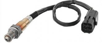
Device diagram
Let's look at the probe diagram to give an idea of the node placement. Knowledge of the design allows you to understand the position of parts susceptible to failure.
Probe design example
- 1 - metal fitting, designed for installing a probe, there are turnkey edges on the outer surface, the thread is located at the bottom;
- 2 - ceramic insulator;
- 3 - sealing element for entering electrical wiring;
- 4 - signal cables;
- 5 - metal protective cap with ventilation ducts, designed to protect the measuring element from damage;
- 6 — spring contact part;
- 7 — ceramic sensitive element;
- 8 - heating rod;
- 9 - ventilation duct;
- 10 - outer metal casing.
Signs of a malfunctioning oxygen sensor on a Lada Priora car
The symptoms are in many ways similar to other breakdowns, so it is important to correctly identify the breakdown at the initial stage.
- Difficulty starting the engine “cold” or “hot”;
- Increased fuel consumption;
- Power reduction;
- Passive acceleration dynamics;
- The engine is not running properly;
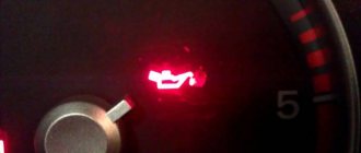
- An indicator on the instrument panel indicates the presence of system errors in the electronic control unit;
- Periodic shooting sounds are heard from the exhaust pipe, which indicates an enrichment (leanness) of the combustible mixture;
- Blue, gray, black smoke from the exhaust pipe.
If one or more signs are detected, immediately contact a service station specialist for a comprehensive diagnosis.
How to check with a multimeter
The tester can check the operation of the heating component of the oxygen sensor:
- The diagnostic device switches to the resistance parameter measurement mode.
- The probes of the device are connected to the heater contacts. These elements are usually made of cable with a large cross-section.
- The contacts of the heating device are ringing.
- If the heating element is working, then the resulting resistance value will be less than 10 ohms. If this parameter is higher, then the electric heating device has failed and needs to be replaced.
The tester checks like this:
- Locate the controller mounting location under the hood of your vehicle.
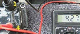
- Connect the multimeter probes to the signal outputs of the sensor or electrical circuits. The tester itself sets the measurement limit to 2 volts.
- At the next stage, it is necessary to artificially create a situation of an over-enriched combustible mixture. To do this, you can use the throttle change method by periodically pressing the gas pedal. Or you can remove the pressure sensor connector.
- Then the readings given by the tester are read. Ideally, they should be from 0.8 volts, this indicates that the oxygen sensor is working properly.
- It is necessary to artificially create a lean mixture situation. To do this, you can create an air leak by slightly loosening the air duct clamp. With a lean mixture, the tester reading should be no more than 0.2 volts.
V_i_t_a_l_y talked about diagnosing the oxygen controller using a multimeter.
Do-it-yourself controller diagnostics on a VAZ 2110 Priora
To check the equipment we use a multimeter. Most motorists have the device in their garage. The sequence of actions is as follows:
- We place the car above the inspection hole;
- Remove the limit switches;
- Connect the multimeter terminals;
- We activate the device to the “Resistance” position;
- We analyze the received data.
If the arrow tends to infinity, the lambda probe is working; if the arrow drops to zero, the part is damaged. Remember that the controller is non-separable and cannot be prevented.
Main set of sensors for 16-valve VAZ-2112 engines
The ECU must check many parameters simultaneously. The most important information will be the position of the crankshaft. It is possible to disable all sensors except the DPKV, and this will not lead to the engine stopping.
Sensors connected to the ECU
Let's list all the elements in order:
- 15 — DTOZH. The resistor is screwed into the thermostat housing. The antifreeze temperature is determined;
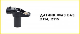
- 17 - DPRV, also known as DF (phase sensor). The operating principle is the Hall effect. The position of the camshaft is controlled. Check it out here.;
- 20 - TPS. Resistance attached to the throttle assembly 19. The angle of deflection of the throttle valve is measured;
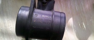
- 21 - Mass air flow sensor. The sensor is connected to the filter housing. Check the air flow, the main symptoms of its malfunction are discussed here;
- 22 - MAC. Not a sensor, but a regulator (electromagnet). Used in standby mode. Check and diagnose it here. About replacing the IAC here.;
- 24 - lambda probe or lambda probe (see above);
- 25 - speed sensor. Fixed in the shift slot. Operating principle: Hall effect;
- 26 - DPKV. Electromagnetic sensor. The position of the crankshaft is controlled;
- 27 –DD (knock sensor). A piezoelectric element is attached to the outer wall of the cylinder block.
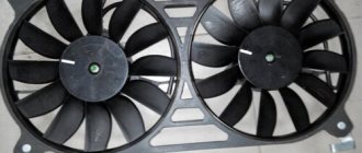
Let's see how all the elements look in real life. Images of VAZ-2112 sensors (16-valve internal combustion engine) are shown.
Every item will be easy to find under the hood
All of the above is true for two engines at once - for units 21124 and 21120 (1.6 and 1.5 l).
Do not unscrew the DTOZH sensor without draining the coolant. And disconnecting the sensor means disconnecting the connector, not disassembling the sensor itself.
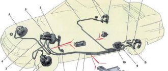
Where is which sensor located - engine compartment diagram
Let's look at another image.
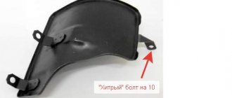
Hood and engine compartment 21124
It is important to understand where the following elements are located:
The position of the phase sensor is shown in the previous chapter.
Never unscrew the speed sensor. It will be difficult to install in such a way as to maintain a seal.
Installing an oxygen sensor on Lada Priora
- We install the machine on the inspection channel (pit);
- We turn off the engine, open the hood;
- We wait until the exhaust system cools down to a safe temperature so as not to damage the skin of the hands;
- Remove the limit switches;
- Use the key to “17” to unscrew the sensor;
- We screw in the DC, put on the terminals;
- We start the engine, all that remains is to check the functionality.
DIY replacement completed.
LADA PRIORA 21723
Assignment of contacts of the instrument cluster block
1 To the electric power steering 2 To the hazard warning lamp 3 To the emergency oil pressure sensor 4 To the parking brake switch 5 To the immobilizer control unit 6 To the airbag control unit 7 To the exterior lighting switch 8 To the turn signal switch (starboard side) 9 To the indicator switch turn (left side) 10 To the fuel injection system control unit 11 To the front passenger airbag deactivation sensor 12 To the seat belt sensor not fastened 13 To the control unit of the electronic brake force distributor 14 To the “RESET” button on the steering column switch (-) 15 To the level sensor brake fluid 16 To the control sensor of the anti-lock braking system 17 To the high beam switch 18 To the instrument cluster lighting switch 19 Housing 20 To terminal “30” of the battery 21 To terminal “15” of the ignition switch 22 To the fuel consumption sensor 23 To the function switching mode key trip computer in a ring forward and changing the minutes (-) 24 To the mode key for switching the functions of the trip computer in a ring back and setting the clock (-) 25 To the outside temperature sensor (-) 26 To the outside temperature sensor (+) 27 To the fuel level sensor 28 To the speed sensor 29 To the coolant temperature sensor 30 Low-voltage tachometer input 31 Diagnostics during production of the instrument cluster 32 To the “L” terminal of the generator relay regulator
List of elements of the electrical connection diagram of the rear wiring harness of LADA PRIORA
1 – rear wiring harness block to the instrument panel wiring harness block; 2 – rear wiring harness block to additional wiring harness block 2 (left rear door); 3 – rear wiring harness block to side door wiring harness block (right front door); 4 – left side direction indicator; 5 – electrical package controller; 6 – right side direction indicator; 7 – interior lighting unit; 8 – handbrake warning lamp switch; 9 – left lamp; 10 – right lamp; 11 – interior air temperature sensor; 12 – interior lamp switch in the driver’s door pillar; 13 – switch for the interior lighting in the pillar of the right front door; 14 – switch for the interior lighting in the pillar of the right rear door; 15 – interior light switch in the left rear door pillar; 16 – block of the rear wiring harness to the block of the wiring harness of the side doors 2 (left front door); 17 – block of the rear wiring harness to the block of the additional wiring harness (right rear door); 18 – blocks of the rear wiring harness to the rear right loudspeaker; 19 – blocks of the rear wiring harness to the rear left loudspeaker; 20 – cigarette lighter; 21 – electric fuel pump module; 22, 23 – rear wiring harness blocks to instrument panel wiring harness blocks 2,3; 24 – trunk lighting; 25 – additional brake signal; 26 – trunk lock drive switch; 27 – interior lamp; 28 – rear wiring harness block to the front wiring harness block; 29 – left rear speed sensor; 30 – right rear speed sensor; 31 – sensor for automatic glass cleaning system (rain sensor); 32 – rain sensor sensitivity regulator; 33 – rear wiring harness block to instrument panel wiring harness block 4; 34 – block of the rear wiring harness to the block of the wiring harness of the parking system sensors; 35 – alarm unit for safe parking system; 36 – driver’s seat belt pretensioner; 37 – passenger seat belt pretensioner; 38 – rear wiring harness block to side door wiring harness block 3 (right front door); 39 – airbag control unit; 40 – parking system control unit; 41 – block of the rear wiring harness to the block of the rear additional wiring harness (tailgate); 42 – rear wiring harness block to rear additional wiring harness block 2 (tailgate); 43 – left seat heater; 44 – switch for electric seat heaters; 45 – right seat heater. 46 – rear wiring harness block to the parking system switch.
Installation of blende
Perform installation only in specialized auto repair shops, as special equipment is required:
- Welding machine;
- Sander;
- Metal pipe;
- Flange connections.
The installation steps are as follows:
- Disable the current sensor;
- Cut out the catalyst on the exhaust pipe section;
- Weld the metal insert;
- Screw in the DC together with the spacer.
If the owner of a VAZ 2110 wants to install an electronic trick, then this will require flashing the ECU with a portable scanner.
Repair
The types of work performed depend on what signs of malfunction were identified during the diagnosis.
Wiring repair
If visible or internal violations are detected, the wiring must be repaired or replaced.
Connector repair
In case of mechanical failure of the connector, it must be replaced, since it will not provide insulation of the connected contacts.
If the connector becomes oxidized, it must be reconnected and the contacts cleaned.
Cleaning (temporary measure)
During the operation of the vehicle, a significant layer of carbon deposits accumulates on the surface of the sensor.
Cleaning is carried out using phosphoric acid and a brush made of soft material. The outer electrode and protective casing must be soaked for about 20 minutes until the accumulated carbon deposits are removed, or cleaned with a brush.
It is not recommended to use products made from hard materials, for example: metal brushes, screwdrivers, sandpaper.
After cleaning, the lambda probe must be completely dried.
Replacement
Replacing the first or second sensor consists of the following steps:
- disconnecting the connector;
- removing the lambda probe from the exhaust system;
- installing a known-good sensor;
- connector connection.
After repairing, cleaning or replacing the elements of the lambda probe, it is necessary to recheck its operation by starting the engine and warming it up to operating temperature.