I'm finishing off the topic of brakes. Because if the brakes are done thoroughly, then “in a circle”, with preventive maintenance of the front and rear calipers, always the main one, and replacing the line with at least copper.
I figured out the front calipers, the rear ones - in theory, I need to replace the rubber bands with Feng Shui ATE, I'll reinstall the pipes with copper, instead of the sorcerer I'll put a brake valve in the rear circuit, and the main brake...
Perhaps, in my mind, it needs to be replaced with something nicer than stock, but first, I’ll take a look inside. After all, if everything is in order there, then let the car run in on the stock brake master cylinder, and then let the owner install something better at his own discretion, and at that time he can understand the degree of “arrival” from this replacement
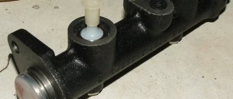
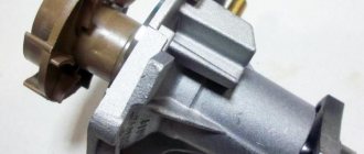
So, here is the standard GTZ VAZ-2110 from Nezhdanchik
The first step is to inspect the tank.
brrr (Off with it and in the trash,
Fortunately, a new one costs a penny even in our outback. After all, no matter how hard you try, you won’t be able to wash this sediment out because of the shape of the tank.
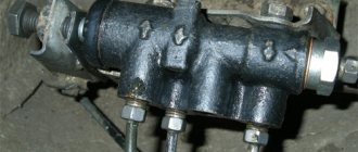
I'm dismantling the GTZ. Attention, you need to remove the filling towards the VUT stem. When removing the plugs to the side, you risk damaging the cuffs on the threads
Disqueri. "how does it work" ))))
Well, surprise, the inside of the GTZ is like new, without wear. Perhaps it was replaced not so long ago. The surface usually shows marks from processing, the photo does not show it (
I sand with water, sandpaper 500-800-1000-1500-2000-2500 without fanaticism
Here, now a real mirror! Again, you can’t see it in the photo(
I wash the filling, dry it, inspect and feel the rubber bands, decide to put them back, lubricate them with mounting paste and carefully assemble them.
Hydraulic brake circuit diagram
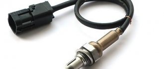
1 – front wheel brake mechanism; 2 – pipeline of the “left front–right rear brake” circuit; 3 – main cylinder for hydraulic brakes; 4 – pipeline of the “right front–left rear brake” circuit; 5 – master cylinder reservoir; 6 – vacuum booster; 7 – rear wheel brake mechanism; 8 – elastic lever of the pressure regulator drive; 9 – pressure regulator; 10 – pressure regulator drive lever; 11 – brake pedal; A – flexible hose of the front brake; B – flexible rear brake hose
The car uses a working brake system with diagonally separated circuits, which ensures high active safety of the car. One hydraulic drive circuit ensures the operation of the right front and left rear brake mechanisms, the other - the left front and right rear.
If one of the circuits of the service brake system fails, the second circuit is used to stop the vehicle with sufficient efficiency.
The hydraulic drive includes a vacuum booster 6 and a dual-circuit pressure regulator 9 for the rear brakes.
The parking brake system is driven by the brake mechanisms of the rear wheels.
Disassembly
To replace and repair a damaged master brake cylinder, you need to remove it from the VAZ 2110; to do this, you should carry out several steps:
- Carefully disconnect all pipelines from a part such as the main cylinder;
- Disconnect the block equipped with wires from the emergency brake fluid indicator. They are connected by terminals;
- It is necessary to prevent fluid leakage and contamination of the mechanism; to do this, it is necessary to cover the openings of the unit and pipelines;
- Next, you need to remove it along with the tank; to do this, unscrew the fastening nuts that secure it to the vacuum type amplifier;
- After the VAZ 2110 fluid level sensor is removed, you need to drain all the brake fluid from the cylinder and basque;
We can only add to this that if there is no great need, you should not remove the reservoir from the master cylinder. To completely disassemble it, you need to remove the tank. Assemble and then install in place in exactly the reverse order.
Before you begin assembling the unit, all components must be washed with purified brake fluid or isopropyl alcohol. After this, everything must be carefully dried using a compressor, and then each of them must be wiped with a dry, clean cloth.
The main thing is not to get mineral oils directly or indirectly on the components; it is also dangerous for the front components of the main type brake cylinder, kerosene and diesel fuel to get on them.
If you find that the brake pedal has increased travel, it is recommended to bleed the brakes. The intricacies of the procedure can be found in this article: https://vazweb.ru/desyatka/tormoza/kak-prokachat-tormoza.html
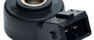
Vacuum booster
1 – vacuum booster housing;
2 – amplifier housing cup; 3 – rod; 4 – adjusting bolt; 5 – rod seal; 6 – sealing ring of the master cylinder flange; 7 – diaphragm return spring; 8 – amplifier pin; 9 – tip mounting flange; 10 – valve; 11 – hose tip; 12 – diaphragm; 13 – amplifier housing cover; 14 – sealing cover; 15 – piston; 16 – protective cover of the valve body; 17 – air filter; 18 – pusher; 19 – pusher return spring; 20 – valve spring; 21 – valve; 22 – valve body bushing; 23 – rod buffer; 24 – valve body; A – vacuum chamber; B – atmospheric chamber; C, D – channels The rubber diaphragm 12 together with the valve body 24 divides the cavity of the vacuum amplifier into two chambers: vacuum A and atmospheric B. Chamber A is connected to the engine inlet pipe through the check valve of the tip 11 and a hose.
The 24 valve body is plastic. At the exit from the cover, it is sealed with a corrugated protective cover 16. The valve body contains the main cylinder drive rod 3 with a support sleeve, rod buffer 23, valve body piston 15, valve assembly 21, pusher and valve return springs 19 and 20, air filter 17 , pusher 18.
When you press the pedal, the pusher 18, the piston 15, and after them the valve 21 move until it stops against the seat of the valve body. In this case, cameras A and B are separated. As the piston moves further, its seat moves away from the valve and through the resulting gap, chamber B is connected to the atmosphere. The air entering through filter 17, the gap between the piston and the valve and channel D creates pressure on the diaphragm 12. Due to the difference in pressure in chambers A and B, the valve body moves along with the rod 3, which acts on the piston of the main cylinder.
When the pedal is released, valve 21 moves away from the body seat and through the resulting gap and channel C of chambers A and B communicate with each other.
Malfunctions and ways to check them
It is possible that you may need to replace the vacuum booster on your VAZ 2110. The cause may be various malfunctions, the characteristic symptoms of which are as follows:
- When you press the brake pedal, a hissing noise occurs, and at the same time, the engine speed often increases;
- The car starts to shake;
- Spark plugs stop working efficiently;
- Fuel consumption increases noticeably.
Before replacing the vacuum booster on a VAZ 2110, it should be checked.
This procedure is performed as follows:
- As with normal bleeding of brakes, with the engine not running, press the gas pedal several times;
- After 5 or 6 presses, keep the pedal in the down position, resting it on the floor, and start the engine;
- After starting, the pedal itself will move forward a little.
There is also a high probability of damage to the diaphragm, on which a hole is formed over time. You can purchase the diaphragm with a repair kit, the cost of which is no more than 500 rubles.
Replacement
To replace an element, you need to understand the main issue - how to remove the vacuum booster from a VAZ 2110. Directly replacing the old element with a new one will not be difficult, just like the reassembly process.
Therefore, we will tell you about the main thing - dismantling the amplifier. Let's start with the fact that the procedure is not complicated, but it requires accuracy and sequence of steps. If you follow the recommendations, the work will take little time and will not take much effort.
- Disconnect the block with wires, which includes brake fluid level sensors in its design.
- Hold the booster check valve with one hand and carefully disconnect the hose with the other. It is advisable to disconnect the hose with a strong hand, since this will require a lot of force.
- Remove the two bolts connecting the booster and master cylinder.
- Carefully remove the cylinder from the amplifier.
- There is no point in disconnecting the brake lines.
- Give access to the dashboard, which will allow you to unscrew the nuts holding the brake pedal bracket. There should be 4 of them.
- It is recommended to dismantle the bracket and amplifier through the engine compartment, since there is enough free space for such manipulations.
- Remove the pin lock plate. To do this, pry the finger with a screwdriver and squeeze it out.
- Now you can easily disable the brake pedal and booster.
- To disconnect the amplifier and bracket, you will have to unscrew the two nuts on the mount.
- A new one is installed in place of the dismantled old vacuum amplifier, and the reassembly procedure is performed in strict sequence of the dismantling process.
Pressure regulator drive
1 – pressure regulator; 2, 16 – pressure regulator mounting bolts; 3 – bracket for the pressure regulator drive lever; 4 – pin; 5 – pressure regulator drive lever; 6 – axis of the pressure regulator drive lever; 7 – lever spring; 8 – body bracket; 9 – pressure regulator mounting bracket; 10 – elastic lever of the pressure regulator drive; 11 – earring; 12 – earring bracket; 13 – washer; 14 – retaining ring; 15 – bracket pin; A, B, C – holes
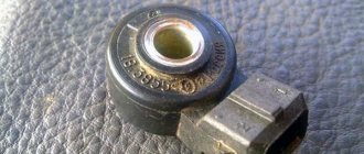
Pressure regulator
1 – pressure regulator housing;
2 – piston; 3 – protective cap; 4, 8 – retaining rings; 5 – piston sleeve; 6 – piston spring; 7 – body bushing; 9, 22 – support washers; 10 – sealing rings of the pusher; 11 – support plate; 12 – pusher bushing spring; 13 – valve seat sealing ring; 14 – valve seat; 15 – sealing gasket; 16 – plug; 17 – valve spring; 18 – valve; 19 – pusher bushing; 20 – pusher; 21 – piston head seal; 23 – piston rod seal; 24 – plug; A, D – chambers connected to the main cylinder; B, C – chambers connected to the wheel cylinders of the rear brakes; K, M, N – clearances The pressure regulator regulates the pressure in the hydraulic drive of the brake mechanisms of the rear wheels depending on the load on the rear axle of the car. It is included in both circuits of the brake system and through it brake fluid flows to both rear brake mechanisms.
Required Tools
If you plan to do the repair yourself, then you need to check the availability of the following tools and materials:
- Screwdriver Set.
- Brake fluid.
- Special wrench for disassembling brakes “10”.
- Socket wrench “17”.
- Plug fittings.
- Pliers.
- Rubber caps.
- A set of keys.
- Socket wrench "13".
Advice! If in the VAZ 2110 mechanism, in addition to the sealing rings, other parts are damaged, then only replacing the GTZ will help. If the remaining elements are fully operational, you need to buy new rings and install them in place of the damaged parts.
Master cylinder with reservoir
1 – main cylinder body; 2 – low pressure sealing ring; 3 – drive piston of the “left front–right rear brake” circuit; 4 – spacer ring; 5 – high pressure sealing ring; 6 – pressure spring of the sealing ring; 7 – spring plate; 8 – piston return spring; 9 – washer; 10 – locking screw; 11 – drive piston of the “right front–left rear brake” circuit; 12 – connecting sleeve; 13 – tank; 14 – brake fluid emergency level sensor; A – gap
Master cylinder with sequential pistons. A tank 13 is mounted on the master cylinder body, in the filler neck of which a sensor 14 for emergency brake fluid level is installed. The high pressure O-rings 5 and the rear wheel cylinder rings are interchangeable.
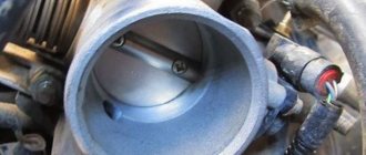
Front wheel brake
1 – brake disc;
2 – pad guide; 3 – caliper; 4 – brake pads; 5 – cylinder; 6 – piston; 7 – pad wear indicator; 8 – sealing ring; 9 – protective cover of the guide pin; 10 – guide pin; 11 – protective casing The front wheel brake mechanism is disc, with automatic adjustment of the gap between the pads and the disc, with a floating caliper and a brake pad wear indicator. The bracket is formed by a caliper 3 and a wheel cylinder 5, which are tightened with bolts. The movable bracket is bolted to pins 10, which are installed in the holes of the guide 2 of the pads. Lubricant is placed in these holes, rubber covers 9 are installed between the pins and the pad guide. Brake pads 4 are pressed against the grooves of the guide by springs, the inner one of which has a lining wear indicator 7.
A piston 6 with a sealing ring 8 is installed in the cavity of the cylinder 5. Due to the elasticity of this ring, the optimal gap between the pads and the disk is maintained.
Tools that will be needed during the replacement process
To replace the brake cylinder you will need a tool.
Before starting any repair work, you should prepare thoroughly. Replacing the brake master cylinder is no exception. To replace this part you will need:
- Set of keys. Having a variety of sockets and socket wrenches will be a huge advantage.
- Screwdriver Set.
- Round nose pliers will help when changing cuffs.
- Special “brake” wrench for 10.
In addition, during the replacement process, brake fluid will spill out, which is generally advisable to replace with new one. DOT-4 brake fluid is suitable for the VAZ-2110.
The process of removing the old part
In order to remove the brake master cylinder, you need to open the hood and do the following:
- To get to the part, you will first have to remove the sound insulation. You should not try to tear it off, as it is secured with bolts. Therefore, you should arm yourself with a screwdriver and unscrew all the fasteners. If the sound insulation is not removed after this, it means that not all fasteners have been unscrewed. If you pull the element, it can be damaged. After this, you can start replacing.
We unscrew several screws using a Phillips screwdriver to remove the sound insulation.
Disconnect the terminal with wires.
We disconnect the tubes and put rubber caps on them.
Wheel cylinder
1 – block stop; 2 – protective cap; 3 – cylinder body; 4 – piston; 5 – seal; 6 – support plate; 7 – spring; 8 – crackers; 9 – thrust ring; 10 – thrust screw; 11 – fitting; A – slot on the thrust ring
The rear wheel brake mechanism (Fig. Rear wheel brake mechanism) is drum-type, with automatic adjustment of the gap between the shoes and the drum. The automatic clearance adjustment device is located in the wheel cylinder. Its main element is a split thrust ring 9 (Fig. Wheel cylinder), installed on the piston 4 between the shoulder of the thrust screw 10 and two nuts 8 with a gap of 1.25–1.65 mm.
The thrust rings 9 are inserted into the cylinder with tension, providing a shear force of the ring along the cylinder mirror of at least 343 N (35 kgf), which exceeds the force on the piston from tension springs 3 and 7 (see Fig. Brake mechanism of the rear wheel) of the brake pads.
When, due to wear of the linings, the gap of 1.25–1.65 mm is completely removed, the shoulder on the thrust screw 10 (see Fig. Wheel cylinder) is pressed against the shoulder of the ring 9, as a result of which the thrust ring moves after the piston by the amount of wear. When the braking stops, the pistons are moved by the force of the tension springs until the cracks stop against the shoulder of the thrust ring. This automatically maintains the optimal clearance between the pads and the drum.
Nuances of repair
O-rings require special attention. The time the rings are in isopropyl alcohol should not exceed twenty seconds, after which they should be dried immediately using a compressor.
The surfaces of the mirror, as well as the piston elements, must be completely clean and free of rust. Every disassembly and repair of a faulty brake master cylinder must be accompanied by replacement of the O-rings, even if they are in good condition. The cuffs of the device also require attention; if they are swollen and frayed, they must be replaced.
Brake hoses are used to supply brake fluid from the master cylinder. If there are cracks or abrasions, they must be replaced. Details: https://vazweb.ru/desyatka/tormoza/zamena-tormoznyh-shlangov.html
After all, it is necessary to check the elasticity of the piston springs; this should be done under load. The length of the spring under load should be 39.01–45.9 N (3.8–4.8 kgf) - 41 mm, with another option the following indicators should be 82.01–99.48 N (8.35–10 .15 kgf) – 21 mm. When free, the spring should have a length of 59.8 mm. If the springs do not have such indicators, then they must be replaced.