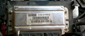
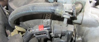
Controller 21114-1411020-31 manufactured by AVTEL has been installed on VAZ tenth series cars since the end of 2005. This block belongs to the Euro 2 environmental standard, i.e. the mandatory presence of an oxygen sensor and adsorber is assumed. Controller 21114-1411020-31 provides pairwise parallel injection. When working with this unit, the vehicle configuration must contain an ignition coil with a 3-pin input, a BOSCH 0 280 218 116 mass air flow sensor and SIEMENS 6393 injectors.
The engine control unit software 21114-1411020-31 has three calibrations in hardware implementation 7.2 A204DM53, A204DM54 and A204DO57. They are usually referred to as 1st, 2nd and 3rd versions. The first two versions are unsuccessful, so VAZ recommends replacing them with the third. This block can be easily chipped, so it is in demand among sports tuning enthusiasts. After several years, a new hardware implementation was created designated as 7.2+, having one calibration A204DP57. The body of the 7.2+ controllers was made by stamping from very thin metal, for which people called this group of controllers “canned food”. The weak point of all types of controllers 21114-1411020-31 is the low quality of the output ignition keys. If the key fails, repairs must be carried out by a very qualified technician, since the key must be soldered to the board with its entire plane to ensure heat dissipation. It is difficult to achieve this and not burn the key when soldering, and therefore, if you are not a master radio installer, it is better to replace the unit with a new one. Dry the interior floor regularly, since the surface of the controller board is not varnished and it is susceptible to dampness.
ECU controller January 7.2 21114-1411020-31 Avtel
An electronic control unit (ECU) is a computing device whose main task is to process information coming from input sensors and, based on this information, to issue control commands to various vehicle systems. The operation of systems and assemblies of a modern car directly depends on the correct operation of this “think tank”. Any malfunctions in the electronic unit are immediately reflected in the operation of the power supply, transmission, exhaust system and other elements. Also called: Controller, Brains, ECU, ECM.
Vendor code: 21114-1411020-31
Applicability: VAZ 2110, 2111, 2112 with an 8-valve 1.6L engine with one oxygen sensor
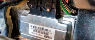
Where is the VAZ 2114 ECU located?
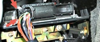
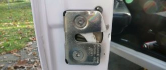
The block is located in the dashboard, directly under the tidy. To replace or dismantle, you need to unscrew the screws and remove the panel from the side, on the passenger side. Through the resulting hole you can see the ECU housing - it is installed inside a steel retainer.
To remove the electronic control unit, you need to unscrew the bolt and carefully pull out the housing, grasping the latch. Of course, it is necessary to turn off the power from the on-board network, otherwise expensive equipment can be damaged. A short circuit is the enemy of any electrical appliance, so be careful. It is advisable not only to remove ground from the battery, but also to disconnect the positive wire.
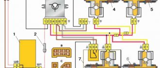
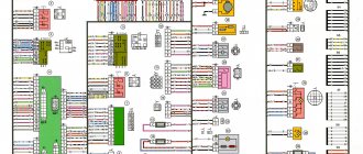
Diagram of the engine control system (ECM) VAZ-2113, 2114 and 2115
Engine control system (ECM) diagram Euro-2 Bosch 7.9.7, January 7.2 VAZ-2113, 2114 and 2115 (2111-1411020-80, 81.82). Engine 1.5 liter 8 valve.
- — controller;
- — block of the ignition system harness to the ABS cabin group harness;
- — diagnostic block;
- — immobilizer warning sensor (APS);
- — immobilizer control unit (APS);
- - ignition coil;
- - spark plug;
- — nozzles;
- — electric fuel pump;
- — block of the ignition system harness to the electric fuel pump harness;
- — block of the fuel level sensor harness to the ignition system harness;
- — block of the ignition system harness to the injector harness;
- — block of the injector harness to the ignition system harness;
- - speed sensor;
- — idle speed regulator;
- — throttle position sensor;
- — coolant temperature sensor;
- — mass air flow sensor;
- — camshaft position sensor (phases);
- — oxygen sensor;
- — crankshaft position sensor;
- - knock sensor;
- — solenoid valve for purge of the adsorber;
- — block of the ignition system harness to the instrument panel harness;
- — controller power supply fuse;
- - ignition relay;
- — ignition relay fuse;
- — fuse for the power supply circuit of the electric fuel pump;
- — electric fuel pump relay;
- — electric fan relay;
- — block of the ignition system harness to the air conditioning harness;
- — pads of the ignition system harness to the front harness;
- — electric cooling system fan;
- — block of the instrument panel harness to the ignition system harness;
- — ignition switch;
- — instrument cluster;
- — on-board control system unit;
- - starter relay;
- — mounting block;
- A - to the “plus” terminal of the battery; B1, B2 - grounding points of the ignition system harness; 2115-3724026-11 — Ignition system harness;
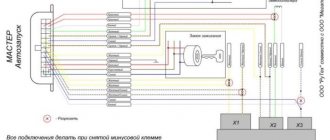
Diagram of the engine control system (ECM) Euro-2 Bosch 7.9.7, January 7.2 VAZ-2113, 2114 and 2115 (21124-1411020-30, 21124-1411020-31.32). 1.6 liter 16 valve engine with individual ignition coils.
- — block of the ignition coil wiring harness to the ignition system harness;
- — block of the ignition system harness to the ignition coil wiring harness;
- — ignition coils;
- — immobilizer warning sensor;
- — immobilizer control unit;
- - spark plug;
- — nozzles;
- — diagnostic block;
- — block of the ignition system harness to the ABS cabin group harness;
- — controller;
- — electric fuel pump;
- — block of the ignition system harness to the fuel level sensor harness;
- — block of the fuel level sensor harness to the ignition system harness;
- — block of the ignition system harness to the injector harness;
- — block of the injector harness to the ignition system harness;
- — block of the ignition system harness to the side door harness;
- - speed sensor;
- — idle speed regulator;
- — throttle position sensor;
- — coolant temperature sensor;
- — mass air flow sensor;
- — oil pressure warning lamp sensor;
- — camshaft position sensor (phases);
- — oxygen sensor;
- — crankshaft position sensor;
- - knock sensor;
- — solenoid valve for purge of the adsorber;
- —
- — coolant temperature indicator sensor;
- — block of the ignition system harness to the instrument panel harness;
- — block of the instrument panel harness to the ignition system harness;
- - ignition relay;
- — ignition relay fuse;
- — fuse for the power supply circuit of the electric fuel pump;
- — electric fuel pump relay;
- — electric fan relay;
- — controller power supply fuse;
- — ignition system harness block to the air conditioner connector;
- — instrument cluster;
- — ignition switch;
- — electric cooling system fan;
- — on-board control system unit;
- — additional starter relay;
- — contacts of the 8-terminal blocks of the instrument panel harness and the front harness;
- — contacts of the 21-terminal blocks of the instrument panel harness and the rear harness;
- - trip computer;
- — diagnostic connector;
- A, E - to the “plus” terminal of the battery; B1 — grounding point of the ignition coil wiring harness; B2 — grounding point of the fuel level sensor harness; B3, B4 - grounding points of the ignition system harness; C - to the starter; D — to the driver's door interior lamp switch;
Diagram of the engine control system (ECM) Euro-3 Bosch 7.9.7+, M73 VAZ-2113, 2114 and 2115 (2111-1411020-30). Engine 1.6 liter 8 valve.
1 - controller; 2 — block of the ignition system harness to the ABS cabin group harness; 3 — diagnostic block; 4 — immobilizer warning sensor (APS); 5 — immobilizer control unit (APS); 6 — ignition coil; 7 — spark plugs; 8 — nozzles; 9 — electric fuel pump; 10 — block of the ignition system harness to the fuel level sensor harness; 11 — block of the fuel level sensor harness to the ignition system harness; 12 — block of the ignition system harness to the injector harness; 13 — injector harness block to the ignition system harness; 14 — speed sensor; 15 — idle speed regulator; 16 — throttle position sensor; 17 — coolant temperature sensor; 18 — mass air flow sensor; 19 — camshaft position sensor (phases); 20 — control oxygen sensor; 21 — crankshaft position sensor; 22 — knock sensor; 23 — solenoid valve for purge of the adsorber; 24 — rough road sensor; 25 — diagnostic oxygen sensor; 26 — block of the ignition system harness to the instrument panel harness; 27 — controller power supply fuse; 28 — ignition relay; 29 — ignition relay fuse; 30 — fuse for the electric fuel pump power supply circuit; 31 — electric fuel pump relay; 32 — electric fan relay; 33 — block of the ignition system harness to the air conditioner harness; 34 — pads of the ignition system harness to the front harness; 35 — electric fan of the cooling system; 36 — block of the instrument panel harness to the ignition system harness; 37 — ignition switch; 38 — instrument cluster; 39 — on-board control system unit; 40 — starter relay; 41 — mounting block;
A - to the “plus” terminal of the battery; B1 — grounding point of the fuel level sensor harness; B2, B3 - grounding points of the ignition system harness;
Diagram of the engine control system (ECM) Euro-3 Bosch 7.9.7+, M73 VAZ-2113, 2114 and 2115 (21124-1411020-10). 1.6 liter 16 valve engine with individual ignition coils and two oxygen sensors.
1 — block of the ignition coil wiring harness to the ignition system harness; 2 — block of the ignition system harness to the ignition coil wiring harness; 3 — ignition coils; 4 — immobilizer warning sensor; 5 — immobilizer control unit; 6 — spark plugs; 7 — nozzles; 8 — diagnostic block; 9 — block of the ignition system harness to the ABS cabin group harness; 10 - controller; 11 — electric fuel pump; 12 — block of the ignition system harness to the fuel level sensor harness; 13 — block of the fuel level sensor harness to the ignition system harness; 14 — block of the ignition system harness to the injector harness; 15 — injector harness block to the ignition system harness; 16 — block of the ignition system harness to the side door harness; 17 — speed sensor; 18 — idle speed regulator; 19 — throttle position sensor; 20 — coolant temperature sensor; 21 — mass air flow sensor; 22 — oil pressure warning lamp sensor; 23 — camshaft position sensor (phases); 24 — control oxygen sensor; 25 — crankshaft position sensor; 26 — knock sensor; 27 — solenoid valve for purge of the adsorber; 28 — diagnostic oxygen sensor; 29 — coolant temperature indicator sensor; 30 — block of the ignition system harness to the instrument panel harness; 31 — block of the instrument panel harness to the ignition system harness; 32 — ignition relay; 33 - ignition relay fuse; 34 — fuse for the electric fuel pump power supply circuit; 35 — electric fuel pump relay; 36 — electric fan relay; 37 — controller power supply fuse; 38 — ignition system harness block to the air conditioner connector; 39 — rough road sensor; 40 — instrument cluster; 41 — ignition switch; 42 — electric fan of the cooling system; 43 — on-board control system unit; 44 - additional starter relay; 45 — contacts of the 8-terminal blocks of the instrument panel harness and the front harness; 46 — contacts of the 21-terminal blocks of the instrument panel harness and the rear harness; 47 — trip computer; 48 — diagnostic connector;
A, E - to the “plus” terminal of the battery; B1 — grounding point of the ignition coil wiring harness; B2, B3 - grounding points of the ignition system harness; B4 — grounding point of the fuel level sensor harness; C - to the starter; D — to the driver's door interior lamp switch;
Throughout the entire operation of the engine, the electronic engine control unit receives, processes, and controls systems and sensors that affect both engine operation and secondary engine elements (exhaust system). The controller uses data from the following sensors:
- DPKV (Crankshaft Position Sensor).
- DF (Phase sensor).
- MAF (instant air flow sensor).
- DTOZH (Coolant temperature sensor).
- TPS (Throttle Position Sensor).
- DK (oxygen sensor).
- DD (Knock Sensor).
- DS (Speed Sensor).
- And other sensors.
Receiving data from the sources listed above, the ECU controls the operation of the following sensors and systems:
- Fuel system (Fuel pump, pressure regulator, injectors).
- Ignition system.
- Idle speed regulator (IAC, IAC).
- Adsorber.
- Radiator fan.
- Self-diagnosis system.
Also, the ECM (ecu) has three types of memory:
- Programmable read-only memory (PROM); Contains the so-called firmware, i.e. a program containing the main calibration readings and engine control algorithm. This memory is not erased when the power is turned off and is permanent. Amenable to reprogramming and chip tuning.
- Random Access Memory (RAM); It is a temporary memory in which system errors and measured parameters are stored. This memory is erased when the power is turned off.
- Electrically reprogrammable memory device (EPROM). This type of memory can be said to be the protection of the car. It temporarily stores codes and passwords for the vehicle's anti-theft system. The immobilizer and EEPROM are compared with data, after which the engine can be started.
How does the ECU work?
At the heart is a microprocessor, which is responsible for the normal functioning of all key devices. On a VAZ 2114 car, the ECU collects data from sensors:
- Vehicle speed.
- Detonations.
- Lambda probe.
- DPKV.
- Air flow.
- TPDZ.
- Phases of injection of the air-fuel mixture.
- Coolant temperatures.
These are reading devices that collect information about the operation of an internal combustion engine. Why does he collect it? It is correct to divide and conquer by the following actuators:
- Fuel supply system (pump, injectors).
- Ignition system.
- Adsorber.
- Ventilation.
- Idle air control (yes, yes, this is not a sensor, but an actuator, no need to be confused).
- Automatic diagnostics.
The block diagram of the electronic control unit on the VAZ 2114 consists of three cascades, each of which has its own memory modules:
- A RAM unit (random access memory) is a system that has short-term memory. It stores all information about errors that occurred during operation during the current engine start. When the ignition is turned off (and the computer is de-energized), all memory is cleared and filled again the next time it starts.
- PROM is a programmable read-only memory device. This is the block in which the fuel map (firmware) of the electronic control unit is stored. It also permanently stores information about all system calibration results. And most importantly, this memory contains the algorithm of the internal combustion engine control system. This memory is permanent and is not erased even if the on-board network is completely disconnected. It is this block that is programmed when the “firmware” procedure is performed to improve the characteristics of the VAZ 2114 car.
- And the last block is the ERPZU. The memory unit is necessary to ensure the normal operation of the anti-theft system on the car. It stores passwords and encodings. Starting the engine is possible only if the data exchanged between the immobilizer and the EEPROM matches.
ECU M74 E-GAS (V8 L1.6 E-4) 2 oxygen sensors
Dear customers, in order to avoid errors when sending an electronic engine control unit (ECU, ECM, controller), in the “Comment” line indicate the toxicity reduction system that complies with Euro 2, Euro 3 or Euro 4 standards, engine displacement and number of valves , number of oxygen sensors, your car model, year of manufacture.
The Electronic Engine Control Unit (ECU) is the “computer” that controls the entire vehicle system. The ECU affects both the operation of an individual sensor and the entire vehicle. Therefore, the electronic engine control unit is very important in a modern car.
The ECU is most often replaced by the following terms: Electronic engine control system (ECM), controller, brains, firmware. Therefore, if you hear one of these terms, then know that we are talking about the “brains”, the main processor of your car. In other words, ECM, ECU, CONTROLLER are one and the same.
The controller (ECU) 11183-1411020-02 (M74) is designed for an eight-valve 1.6-liter engine with Euro-4 environmental standard. This standard is met if the car has 2 oxygen sensors, a neutralizer, an adsorber and an electronic gas pedal. Controller 11183-1411020-02 ensures engine operation in pair-parallel injection mode.
The following firmware versions are available:
Controllers NPO ITELMA M74 / 11183-1411020-02
| Software ID | ECU Hardware ID | Applicability |
| I414DA01 | 11183-1411020-02 | Pre-production version, hardware different from the latest M74 units. Does not work in serial M74 and does not open in ChipTuningPro. |
| I414DB02 | 11183-1411020-02 | M74, serial version, LADA SAMARA 1.6L 8V |
| I414DC03 | 11183-1411020-02 | M74, serial version, LADA SAMARA 1.6L 8V |
| I414DD04 | 11183-1411020-02 | M74, serial version, LADA SAMARA 1.6L 8V |
| I414DE06 | 11183-1411020-02 | M74, serial version, LADA SAMARA 1.6L 8V |
| I414DE07 | 11183-1411020-02 | M74, serial version, LADA SAMARA 1.6L 8V |
Product Features:
The electronic engine control unit (catalog designation "ITELMA" MOSCOW, 11183-1411020-02), using various signals from engine sensors, controls the composition and amount of fuel supplied to the engine.
Other article numbers of the product and its analogues in catalogues: 11183141102002.
VAZ 2111, VAZ 2112, VAZ 2113, VAZ 2114, VAZ 2115 with 2 oxygen sensors. E-GAS (V8, L 1.6; E-4).
Any breakdown is not the end of the world, but a completely solvable problem!
Varieties of electronic engine control systems (ECM, controllers), which are installed on different models of the VAZ family car.
How does a malfunction of the electronic engine control unit (ECU, ECM, controller) manifest itself in a VAZ family car.
How to independently replace the electronic engine control unit (ECU, ECM, controller) on a VAZ family car.
With the AvtoAzbuka online store, repair costs will be minimal.
Just COMPARE and BE SURE!!!
Don't forget to share the information you find with your friends and acquaintances, because they may also need it - just click one of the social networking buttons located above.
Repair and diagnostics of control units
The VAZ 2114 controller often breaks down. The system has a self-diagnosis function - the ECU queries all components and issues a conclusion about their suitability for operation. If any element fails, the “Check Engine” lamp will light up on the dashboard. It is possible to find out which sensor or actuator has failed only with the help of special diagnostic equipment. Even with the help of the famous OBD-Scan ELM-327, loved by many for its ease of use, you can read all engine operating parameters, find the error, eliminate it and delete it from the memory of the VAZ 2114 ECU.
Of course, it is wrong to simply delete errors. Be careful, because malfunctions don’t just appear. A good example is that a friend’s oxygen sensor broke down. And every other day he cuts down the mistake so that “it doesn’t become an eyesore.” But the reason lies in a faulty lambda. But what to do if the ECU does not want to respond to the scanner at all? Then check the following:
- Is there any mechanical damage to the housing, including oxidation and corrosion?
- The fuse is working properly, there is voltage and a connection to the power supply minus.
- Is the device overheating?
ECU Electronic engine control unit JANUARY 7.2 for VAZ 2110-2112
Dear customers, in order to avoid errors when sending an electronic engine control unit (ECU, ECM, controller), in the “Comment” line indicate your car model, year of manufacture and number of valves, engine size.
Electronic engine control unit (ECU) 21114-1411020-31 (JAN 7.2) 81 contacts - “computer” that controls the entire vehicle system. The ECU affects both the operation of an individual sensor and the entire vehicle. Therefore, the electronic engine control unit is very important in a modern car.
ECU 21114-1411020-31 (JANUARY 7.2) 81 pins are most often replaced by the following terms: Electronic engine control system (ECM), controller, brains, firmware. Therefore, if you hear one of these terms, then know that we are talking about the “brains”, the main processor of your car. In other words, ECM, ECU, CONTROLLER are one and the same.
Controller 21114-1411020-31 (JANUARY 7.2) 81 contacts, installed on cars of the tenth VAZ family since the end of 2005. This unit belongs to the Euro 2 environmental standard (i.e., the presence of an oxygen sensor and adsorber is assumed). Engine 8 valves, engine capacity 1.6 L.
The controller firmware in the photo and availability in the warehouse may differ. When ordering, please specify the required firmware.
The following firmware versions are available:
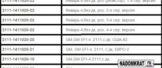
Controllers 21114-1411020-31 January 7.2
| Software ID | ECU | VAZ number | Engine | Toxic norms. | Note |
| January 7.2 produced by AVTEL | |||||
| A204DM53 | January 7.2 | 21114-1411020-31 | 21114 | Euro 2 | 2 Serial version for engine 21114 (1.6) |
| A204DO57 | January 7.2 | 21114-1411020-31 | 21114 | Euro 2 | 3 Serial version for engine 21114 (1.6) |
Product features: Electronic engine control unit (catalog designation "AVTEL", 21114-1411020-31), using various signals from engine sensors, controls the composition and amount of fuel supplied to the engine. Ensures engine operation in pair-parallel injection mode. The vehicle configuration, when working with this unit, must contain an ignition coil with a 3-pin input, a BOSCH 0 280 218 116 mass air flow sensor and SIEMENS VAZ 20734 injectors.
This type of controller 21114-1411020-31 (JANUARY 7.2) 81 contacts, is installed at the factory in a single volume. The bulk of these ECUs are intended for release on the market.
Other articles of the product and its analogues in the catalogs: 21114141102031, 21114-1411020-30 (VS 7.9.7), 21114141102032.
VAZ 2110-2111, VAZ 2112.
Any breakdown is not the end of the world, but a completely solvable problem!
Varieties of electronic engine control systems ECM (ECU, controllers), which are installed on different models of a car of the VAZ family. ECM (ECU, controllers), which are installed on different models of a car of the VAZ family.
How does a malfunction of the electronic engine control unit (ECU, ECM, controller) manifest itself in a VAZ family car.
How to independently replace the electronic engine control unit (ECU, ECM, controller) on a VAZ family car.
AvtoAzbuka online store, repair costs will be minimal.
Just COMPARE and BE SURE!!!
Don't forget to share the information you find with your friends and acquaintances, because they may also need it - just click one of the social networking buttons located above.