Repairs on a forced 1.6-liter engine are a little more complicated: First you need to remove the protective casing and loosen the clamp securing the air filter pipe.
Removing the sensor from the car The idle speed regulator is located in the mounting hole of its unit, that is, the throttle. Fuse 1 provides constant power to the electrical package control unit.
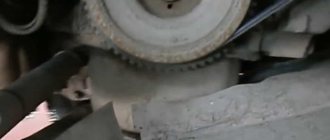
A year later, the Volzhsky Automobile Plant produced the first pilot batch of 50 VAZ cars, and in the same year the hatchback was first introduced to the market. If you removed the sensor from the car, but the engine operation does not change, then that was the reason. Timing marks 8 class VAZ! Installation of timing belt 8kl.VAZ2108,2109,2110,2111,2113,2114,2115
To do this: Remove the wire tip from the spark plug of the first cylinder; We bring it to the metal part of the motor at a distance of mm; Turn on the starter; Let's see if a spark jumps between the wires; Similarly, we check the wires from spark plugs 2, 3 and 4 of cylinders. Advice: if you want to understand the operation of a car’s ignition and power system, it would be a good idea to watch video materials from a school physics course.
The search starts with: Ignition module; ECU - on cars with a VAZ engine To check the ignition coil, you need to use a tester, with which you should measure the resistance of the primary and secondary windings. Once you understand it and understand the principle of operation, you can effectively drive your car and perform minor repairs.
Side door wiring harness connector to instrument panel harness; Side door wiring harness connector to seat heating harness; Electric lock of the right rear door; Harness block to rear right loudspeaker; Harness block to rear left loudspeaker; Door lock control unit; Side door wiring harness connectors to the additional left harness; Side door wiring harness connectors to the additional left harness; Terminals of the side door wiring harness to the radio; Side door wiring harness block to the additional right harness; A1 is the grounding point for the side door wiring harness.
Modification with an 8-valve VAZ engine, 1.6 liters and 81.6 horsepower. But it may be the degree of his sensitivity. This also introduced some complications and additional wiring harnesses, which are shown in the VAZ electrical diagram
relays and fuses for the computer, Carlson and fuel pump
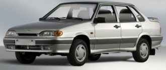
Car modifications 2114
VAZ-21140 . Modification with an 8-valve injection engine VAZ-2111, 1.5 liters and 77 horsepower. Serial production from 2003 to 2007
VAZ-21144 . Modification with an 8-valve VAZ-21114 engine, 1.6 liters and 81.6 horsepower. Years of serial production: 2007-2013.
VAZ-211440 . Another modification released in 2007, it was equipped with a VAZ-11183 engine with a volume of 1.6 liters and a power of 82 horsepower. The car was discontinued in 2013.
VAZ-211440-24 . Released in 2009, a modification with an injection 16-valve VAZ-21124 engine with a volume of 1.6 liters and a power of 89.1 horsepower. Discontinued in 2013.
VAZ-211440-26 . Modification with a 16-valve injection engine VAZ-21126, which complies with the Euro-3 environmental standard, with a volume of 1.6 liters and a power of 98 hp. The car was produced from 2010 to 2013.
Serial firmware VAZ Bosch M7.9.7+
Bosch M7.9.7 new hardware implementation (M7.9.7+) Software ID VAZ number Note B103EQ12 2111 – 1411020-80 1 Serial version for new hardware implementation, E2 standards B103ER12 2111 – 1411020-80 2 Serial version for new hardware implementation, E2 standards B104DQ17 21114 – 1411020-30 1 Serial version for new hardware implementation, E2 standards B104DR17 21114 – 1411020-30 2 Serial version for new hardware implementation, E2 standards B105DQ09 21124 – 1411020-30 1 Serial version for new hardware implementation, E2 B1 standards 05DR09 21124 – 1411020-30 2 Serial version for new hardware implementation, standard E2 B105DR10 21124 – 1411020-30 3 Serial version for new hardware implementation
ECU made in France, E2 standards B108DQ09 21124 – 1411020-10 1 Serial version for new hardware implementation, E3 standards B108DR09 21124 – 1411020-10 2 Serial version for new hardware implementation, E3 standards B109DR02 21124 – 1411020-20 3 Serial version for new device noah implementations, E3 standards B119DQ01 21114 – 1411020-20 1 Euro‑3 serial version for new hardware implementation, XC05_M7A1, E3 standards B119DR02 21114 – 1411020-20 Bogdan, serial version, software XC06_M7A1, E4 standards B120EQ16 21214 – 1411020-30 1 Serial version for new hardware implementation, E2 standards B120ER16 21214 – 1411020-30 2 Serial version for new hardware implementation, E2 standards B120ER19 21214 – 1411020-30 3 Serial version for new hardware implementation, E2 standards B122HR01 21230 – 1411020-90 1 Serial version for new hardware implementation on Niva - Chevrolet vehicles, E2 standards Attention! The firmware has a problem with turning on the fans B122HR91 21230 – 1411020-90 2 Serial version for the new hardware implementation on Niva – Chevrolet, E2 standards 22XC052S 21230 – 1411020 “Clone” B122HR01, E4 standards 22YC041S 21230 – 1411020- 40 Niva – Chevrolet, E4 standards B114ER18 21214 – 1411020-20 Serial version for the new hardware implementation on the Niva 21214 car, E3 standards B114ER17 21214 – 1411020-20 Serial version for the new hardware implementation on the Niva 21214 car. Version from the export car, E3 standards B126ES01 2104 – 1411020-10 1 Serial version for the new hardware implementation for 1.45 l classic cars, E2 standards B126ER02 2104 – 1411020-10 2 Serial version for the new hardware implementation for 1.45 l classic cars, norms E2 B102CQ05 Kalina 1 Serial for Kalina, standards E3 B102CR06 Kalina 2 Serial for Kalina, standards E3 B101CR01 11183 – 1411020-02 1 Serial for Kalina, standards E2 B101CR02 11183 – 1411020-02 2 Serial for Kalina, standards E2 B104CR 01 21114 – 1411020- 40 Viburnum, paper nameplate, E3 standards B104CR02 21114 – 1411020-40 Viburnum, differences from CR01 only in fan temperature thresholds, E3 standards B103CU03 21114 – 1411020-40 Viburnum, paper nameplate, without DND, E3 standards B173DR01 21126 – 141102 0-10 1 Serial for Priora, standards E3 B174DR03 21126 – 1411020-00 2 Serial for Priora, standards E4* B174DR04 21126 – 1411020-00 3 Serial for Priora, equipped with power steering, standards E4* B174DT05 21126 – 1411020-30 4 Serial for Pria yell, norms E4* B174DT06 21126 – 1411020-30 5 Serial for Priora, standards E4* B174DT07 21126 – 1411020-00 6 Serial for Priora, standards E4* B173СR03 11194 – 1411020 1 Serial for Kalina 1.4 l., standards E3 B174 CR03 11194 – 1411020 -10 2 Serial version for Kalina 1.4 l., E3 standards B174СT04 11194 – 1411020-10 3 Serial version for Kalina 1.4 l., E3 standards 22YB072S 2123 – 1411020-30 1 Serial version Euro‑3 for new hardware implementation on a /m Niva - Chevrolet, E3 standards OPP firmware** Bosch M7.9.7+ B120ER1733XCO305B133ER17 21214 – 1411020-30 OPP firmware from Niva 1.8 (in identifiers 1.7)
Without phase sensor. 33XCO305 and B133ER17 are “clones” of B120ER17, E2 standards B121ER17 21214 – 1411020-10 Firmware for STC VAZ OPP for the long Niva, E3 standards B11KSS01 11196 – 1411020 STC VAZ OPP firmware for Kalina Sport 1, 6 16V, standard E3 B13KSS02 21126 – 1411020-60 Firmware for OPP STC VAZ for Kalina Sport 1.6 16V. There are two options in the archive with different KS and identifiers, E3 standards
* Toxicity standards are indicated in accordance with IP VAZ ** OPP - Experimental Industrial Enterprise, a subsidiary of AvtoVAZ. Attention! Some firmware for Bosch M7.9.7 can be presented in two forms, in the compressed “Combiloader” format and regular bin files (with the prefix “c”)
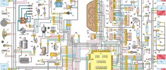
Wiring diagram VAZ-2114 for old models
Electrical diagram of car 2114: 1 - headlight; 2 [Installed on a part of the car] - fog lamp; 3 — ambient air temperature sensor; 4 — electric engine radiator fan; 5 — block for connection to the wiring harness of the engine control system; 6 — engine compartment lamp switch; 7 [Installed on a part of the car] - reserve block for connecting an audio signal with one terminal (the negative terminal is connected to the body); 8 — sound signal; 9 — liquid level sensor in the windshield washer reservoir; 10 [Installed on a part of the car] - brake pad wear sensor; 11 — low oil level sensor; 12 - generator; 13 [Installed on a part of the car] - engine compartment lamp; 14 — temperature indicator sensor; 15 — starter; 16 — battery; 17 [Installed on a part of the car] - relay for turning on fog lights; 18 — coolant level sensor in the expansion tank; 19 — sensor of insufficient brake fluid level; 20 — reversing light switch; 21 — windshield wiper gear motor; 22 — emergency oil pressure sensor; 23 — rear window washer electric pump; 24 — electric pump for windshield washer; 25 — instrument panel; 26 — mounting block of fuses and relays; 27 — brake signal switch; 28 — ignition relay; 29 - ignition switch (lock); 30 — glove box lighting lamp; 31 — switch for the glove compartment lighting lamp; 32 — rear window heating switch; 33 — rear fog light switch; 34 [Installed on a part of the car] - fog light switch; 35 - combined switch for side lights and headlights; 36 — alarm switch; 37 — steering column switches; 38 — brightness control for instrument lighting; 39 — illumination lamp for the headlight hydraulic adjustment control handle; 40 — socket for connecting a portable lamp; 41 — side direction indicator; 42 — interior lighting switch (front door open sensor); 43 — interior lamp; 44 — electric fan of the ventilation and heating system; 45 — additional resistor of the electric fan of the ventilation and heating system; 46 — switch for operating modes of the electric fan of the ventilation and heating system; 47 — illumination lamp for the handle of the operating mode switch of the electric fan of the ventilation and heating system; 48 — backlight lamp for the heater control unit; 49 — display unit of the on-board control system; 50 [Installed on part of the car] - trip computer; 51 — interior lighting switch (rear door open sensor); 52 [Installed on a part of the car] - block for connecting a clock; 53 — fuel module; 54 — ashtray illumination lamp; 55 — cigarette lighter; 56 — interior lamp; 57 — switch for the parking brake warning lamp; 58 — rear light; 59 — license plate light; 60 — additional brake light; 61 — heating element for heating the rear window; 62 — rear window wiper gear motor; A - numbers of pins in connecting blocks.
VAZ-2114 diagram (second option)
Electrical diagram of VAZ-2114 cars (without engine control system):
1 — block headlights; 2 — fog lights; 3 — air temperature sensor; 4 — electric motor of the engine cooling system fan; 5 — blocks connected to the wiring harness of the ignition system; 6 — engine compartment lamp switch; 7 — block for connecting to a single-wire type audio signal; 8 — sound signal; 9 — washer fluid level sensor; 10 — front brake pad wear sensor; 11 — oil level sensor; 12 - generator; 13 — engine compartment lamp; 14 — coolant temperature indicator sensor; 15 — starter; 16 - battery; 17 — relay for turning on fog lights; 18 — coolant level sensor; 19 — brake fluid level sensor; 20 — reverse light switch; 21 — windshield wiper gearmotor; 22 — oil pressure warning lamp sensor; 23 — block for connecting to the rear window washer electric motor; 24 — electric motor for windshield washer; 25 — instrument cluster; 26 — mounting block 2114; 27 — brake light switch; 28 — ignition relay; 29 — ignition switch; 30 — glove box lighting lamp; 31 — glove box lighting switch; 32 — rear window heating element switch; 33 — rear fog light switch; 34 — fog lamp switch; 35 — switch for external lighting lamps; 36 — alarm switch; 37 — steering column switches; 38 — switch for instrument lighting lamps; 39 — lamp for illuminating the headlight hydrocorrector scale; 40 — plug socket for a portable lamp; 41 — side direction indicators; 42 — lamp switch on the front door pillars; 43 — lamp for individual interior lighting; 44 — heater fan electric motor; 45 — additional resistor of the heater electric motor; 46 — heater fan switch; 47 — heater switch illumination lamp; 48 — lamp for illuminating the heater levers; 49 — on-board control system unit; 50 — trip computer; 51 — lamp switch on the rear door pillars; 52 — block for connecting the wiring harness of the engine control system; 53 — electric fuel pump and gasoline quantity sensor; 54 — front ashtray illumination lamp; 55 — cigarette lighter 2114; 56 — trunk lighting lamp; 57 — trunk light switch; 58 — interior lamp; 59 — parking brake warning lamp switch; 60 — rear external lights; 61 — rear internal lights; 62 — block for connection to the rear window heating element; 63 — license plate lights; 64 - additional brake signal located in the spoiler.
Conventional numbering of plugs in blocks:
- A — headlight blocks;
- B — electric fuel pump block;
- C — blocks of the mounting block, ignition switch, windshield wiper gearmotor;
- D — blocks for the interior lamp.
Wiring diagram VAZ-2114 new models
The updated engine has a new injection scheme, so it was necessary to use some new devices, as well as replace the ignition coil with a more efficient one and adapted to Euro 3 conditions. In order to comply with them, the engine had to minimize the amount of CO at start-up. And for this it was necessary to lean the mixture. Since a lean mixture ignites worse, it needed a more powerful spark to spark. This explains the use of a coil of increased power.
- block headlights;
- gearmotors for headlight cleaners*;
- fog lights*;
- ambient temperature sensor;
- sound signals;
- engine compartment light switch;
- engine cooling fan electric motor;
- generator VAZ-2114;
- low oil level indicator sensor;
- washer fluid level sensor;
- front brake pad wear sensor;
- wire ends connected to the common windshield washer pump**;
- windshield washer pump;
- headlight washer pump*;
- wire ends for connecting to the rear window washer pump on VAZ-2113 and VAZ-2114 cars;
- low oil pressure indicator sensor;
- engine compartment lamp;
- wire lug for connecting to the engine management system wiring harness;
- windshield wiper gear motor;
- starter VAZ-2114;
- block connected to the wiring harness of the ignition system on carburetor cars;
- coolant temperature indicator sensor;
- reverse light switch;
- low brake fluid level indicator sensor;
- accumulator battery;
- low coolant level indicator sensor;
- relay for turning on fog lights;
- mounting block;
- brake light switch;
- plug socket for a portable lamp;
- hydrocorrector scale illumination lamp;
- parking brake indicator lamp switch;
- block for connecting a backlight lamp;
- switch for instrument lighting lamps;
- Understeering's shifter;
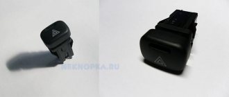
- hazard switch;
- front seat heating element relay;
- ignition switch;
- rear fog lamp circuit fuse;
- front seat heating elements circuit fuse;
- door lock circuit fuse;
- front ashtray illumination lamp;
- ignition relay;
- cigarette lighter VAZ-2114;
- glove box lighting lamp;
- glove compartment light switch;
- heater fan motor;
- additional heater motor resistor;
- heater fan switch;
- heater switch illumination lamp;
- heater lever illumination lamp;
- gear motors for electric windows of the front doors;
- right front door ESP switch (located in the right door);
- gear motors for locking front door locks;
- wires for connecting to the right front speaker;
- gear motors for locking rear doors;
- wires for connecting to the right rear speaker;
- door lock control unit;
- wires for connecting to radio equipment;
- headlight wiper switch*;
- rear window heating element switch;
- rear fog light relay;
- block for connection to the heating element of the right front seat;
- rear fog light switch;
- right front seat heating element switch;
- fog light switch*;
- switch for external lighting lamps;
- left front seat heating element switch;
- block for connection to the heating element of the left front seat;
- wires for connecting to the left front speaker;
- left front door power window switch (located in the left door);
- right front door power window switch (located in the left door);
- wires for connecting to the left rear speaker;
- side direction indicators;
- dome light switches on the front door pillars;
- dome light switches on the rear door pillars;
- lampshade VAZ 2114;
- individual interior lighting lamp;
- block for connecting to the wiring harness of the electric fuel pump;
- trunk light switch;
- instrument cluster;
- trunk light;
- on-board control system display unit;
- trip computer*;
- block for connecting the wiring harness of the engine management system;
- rear exterior lights;
- rear interior lights;
- pads for connecting to the rear window heating element;
- license plate lights;
- additional brake signal located on the spoiler.
Numbering order of plugs in blocks:
A - headlight units and headlight cleaners; B - cigarette lighter; B - mounting block, instrument cluster, ignition switch, windshield wiper and other electrical components (for blocks with a different number of plugs, the numbering order is similar); G — relay for turning on the rear fog light; D — alarm switch; E — electric window motors and door lock motors; F — interior lamp.
In the instrument panel wiring harness, the second ends of the white wires are brought together into one point, which is connected to the instrument lighting switch (except for the white wire, from plug “4” of block “X2” of mounting block 28 to display block 83 of the on-board control system). The second ends of the black wires are also brought together to points connected to ground. The second ends of the yellow wires with a blue stripe are brought together to a point connected to plug “4” of the “X1” block of the mounting block. The second ends of the white wires with a red stripe are brought together to a point connected to plug “10” of the “X4” block of the mounting block. The second ends of the orange wires are brought together to a point connected to plug “3” of the “X4” block of the mounting block.
Explanations for the 8-pin injector block: white-red and blue - for the check light bulb, blue-red - ignition, gray - speed sensor, brown-red - tachometer, blue-white - driver's door switch (for the immobilizer), green- red - K-line (may not exist), green - fuel consumption. Next to it is a pink wire - to the fuel level sensor.
How does it work
The heart of the ECU on the VAZ 2114 is a special microprocessor; its task is to control all systems of the car.
- lambda probe;
- air flow;
- speed;
- injection phases;
- coolant temperature;
- TPDZ;
- detonation;
- DPKV.
Electronics collects all this data together and processes it, but why? In order to adequately respond to all possible changes in the main systems of the machine and bring their operation up to normal.
The following actuators are under the control of the ECU:
- ventilation;
- diagnostic system;
- fuel supply;
- adsorber;
- ignition;
- idling.
The brains of the VAZ 2114 have a memory block diagram consisting of three cascades, each with its own working modules:
- RAM – for people who understand PCs, its functions will not be something new. Essentially, this is RAM in which the current work session is processed, but for the car’s on-board computer.
- PROM is a block of long-term memory. Data about the service, the fuel map, all previous system calibrations, the engine control algorithm and the ECU firmware itself are stored here. The data stored here is not erased under any circumstances. In the light of computer technology, this module is analogous to a PC hard drive. It is in the memory of this module that changes are made during “reflashing” when they want to improve the driving characteristics of the car.
- ERPZU is a module that stands apart from the previous ones. Its main task is to control the car's anti-theft system. Its memory stores encodings, passwords and features of data transfer between the EEPROM and the immobilizer. If the data packets do not match, the module will not allow the engine to start.
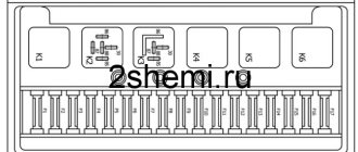
Relays and fuses VAZ 2114
F1 for 10 Amps (A) rear fog lights and rear fog light warning lamp. F2 for 10 A turn signal lamps, turn signal relay, hazard lights, hazard warning lights. F3 7.5 A lamps for interior lighting (both) and trunk, ignition lighting, powertrain control system control lamp, brake lamps, computer, if available. F4 20 A carrier, relay and rear window heating element. F5 20 A horn and its relay, cooling fan. F6 30 A power windows and their relays F7 30 A motor heater, headlight cleaner, windshield washer, cigarette lighter, glove compartment light bulb, rear window heating relay winding. F8 7.5 A right fog lamp. F9 7.5 A left fog lamp. F10 at 7.5 A left side marker, lamp signaling the inclusion of the side light, lamps for illuminating the sign, engine compartment, illumination of switches and instruments, instrument lighting switch. F11 at 7.5 A right side. F12 at 7.5 A right low beam. F13 at 7.5 A left low beam. F14 for 7.5 A left high beam and a light indicating that the high beam headlights are on. F15 at 7.5 A right far. F16 30 A - a light indicating insufficient oil pressure, brake fluid level, engagement of the parking brake, low battery, instrument cluster, relay for monitoring the health of lamps, indication of control systems, reversing lamps, turn indicators and their relays, as well as an alarm if turning mode is turned on, computer, generator excitation winding is turned on at the moment the engine starts.
Engine management system
VAZ-2111 engine with distributed fuel injection to R83-02 toxicity standards with controller 2111-1411020-61 (January-5.1) or 2111-1411020-60 (M1.5.4N) on VAZ-2113, -2114, -2115 vehicles
| 1 – fragment of the mounting block; 2 – electric fan of the engine cooling system; 3 – status indicator of the car anti-theft system; 4 – control unit of the automobile anti-theft system; 5 – coolant temperature sensor; 6 – air flow sensor; 7 – throttle pipe; 8 – block connected to the throttle position sensor; 9 – block connected to the idle speed regulator; 10 – controller; 11 – block connected to the air conditioner wiring harness; 12 – oxygen sensor; 13 – knock sensor; 14 – crankshaft position sensor; 15 – speed sensor; 16 – adsorber; 17 – battery; 18 – main relay; 19 – block connected to the wiring harness of the anti-lock brake system; 20 – diagnostic block; 21 – fuse for protecting the main relay circuits; 22 – controller protection fuse; 23 – fuse for protecting the electric fuel pump and its relay; 24 – relay for turning on the electric fuel pump; 25 – relay for turning on the electric fan; 26, 27 – blocks connected to the instrument panel wiring harness; | 28 – ignition module; 29 – electric fuel pump with fuel level sensor; 30 – spark plugs; 31 – nozzles; F – front harness wire going to the “B+” terminal of the generator; G – wires of the front wiring harness. The order of conditional numbering of plugs in the blocks: A – controller; B – control unit of the automobile anti-theft system; B – indicator of the state of the automobile anti-theft system; G – pads 26; D – throttle pipe; E – air flow sensor; F – electric fuel pump and oxygen sensor; Z – speed sensor; And – ignition module. Purpose of the plugs in block 26 : 1 – to the low-voltage input of the tachometer in the instrument cluster; 3 – to the engine management system control lamp in the instrument cluster (from the controller); 4 – to the lamp switch located on the driver’s door pillar; 5 – to the control lamp of the engine management system in the instrument cluster (supply “+” power); 6 – to the trip computer (fuel consumption signal); 7 – to the instrument cluster (vehicle speed signal); 8 – to terminal “15” of the ignition switch (plug 4 of the switch block). |
VAZ-2111 engine with distributed fuel injection to Euro-2 emission standards with controller 2111-1411020-40 (MP7.0) on VAZ-2113, -2114, -2115 vehicles
| 1 – fragment of the mounting block; 2 – electric fan of the engine cooling system; 3 – status indicator of the car anti-theft system; 4 – control unit of the automobile anti-theft system; 5 – coolant temperature sensor; 6 – air flow sensor; 7 – throttle pipe; 8 – block connected to the throttle position sensor; 9 – block connected to the idle speed regulator; 10 – controller; 11 – block connected to the air conditioner wiring harness; 12 – oxygen sensor; 13 – knock sensor; 14 – crankshaft position sensor; 15 – speed sensor; 16 – adsorber; 17 – battery; 18 – main relay; 19 – block connected to the wiring harness of the anti-lock brake system; 20 – diagnostic block; 21 – fuse for protecting the main relay circuits; 22 – controller protection fuse; 23 – fuse for protecting the electric fuel pump and its relay; 24 – relay for turning on the electric fuel pump; 25 – relay for turning on the electric fan; 26, 27 – blocks connected to the instrument panel wiring harness; 28 – ignition module; 29 – electric fuel pump with fuel level sensor; | 30 – spark plugs; 31 – nozzles; F – front harness wire going to the “B+” terminal of the generator; G – wires of the front wiring harness. |
The order of conditional numbering of plugs in blocks:
A – controller; B – control unit of the automobile anti-theft system; B – indicator of the state of the automobile anti-theft system; G – pads 26; D – throttle pipe; E – air flow sensor; F – electric fuel pump and oxygen sensor; Z – speed sensor; And – ignition module.
Purpose of plugs in block 26:
1 – to the low-voltage input of the tachometer in the instrument cluster; 3 – to the engine management system control lamp in the instrument cluster (from the controller); 4 – to the lamp switch located on the driver’s door pillar; 5 – to the control lamp of the engine management system in the instrument cluster (supply “+” power); 6 – to the trip computer (fuel consumption signal); 7 – to the instrument cluster (vehicle speed signal); 8 – to terminal “15” of the ignition switch (plug 4 of the switch block).
Description of "brains"
The VAZ 2114 ECU is an on-board computer of the vehicle, designed to control the main systems of the car. The parameters of the control module affect both the functionality of certain regulators and the operation of the engine as a whole. That is, the importance of this system cannot be denied.
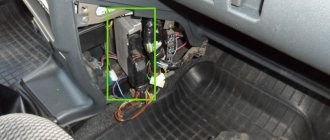
Controller Location
In VAZ 2114 and VAZ 2115 cars, the control module is installed under the center console of the car, in particular, in the middle, behind the panel with the radio. To get to the controller, you need to unscrew the latches on the side frame of the console. As for the connection, in Samar modifications with a one and a half liter engine, the mass of the ECU is taken from the power unit housing, from the fastening of the plugs located to the right of the cylinder head.
Location of the ECU in the Chetyrka
In cars equipped with 1.6- and 1.5-liter engines with a new type of ECU, the mass is taken from the welded stud. The pin itself is fixed on the metal body of the control panel near the floor tunnel, not far from the ashtray. During production, VAZ engineers, as a rule, do not securely fix this pin, so over time it can become loose, which will lead to the inoperability of some devices.
Design and principle of operation
The control unit of the electronic system operates in accordance with the indicators received from the sensors:
- speed;
- detonation;
- lambda probe;
- fuel injection phases;
- crankshaft position;
- throttle position;
- air flow meter;
- antifreeze temperature.
In accordance with the data received from these controllers, the control module controls the following systems:
- ignition;
- adsorber;
- injectors, as well as a fuel pump;
- ventilation and heating system;
- programs for diagnosing vehicle performance;
- idle speed regulator (video author - Evgeniy Vekhter).
As for the device, the control module structurally consists of the following components:
- RAM or random access memory. This module contains basic data about recently identified errors detected by the electronic system in the operation of various components. When the driver turns off the ignition, the RAM unit is updated, causing this data to disappear.
- PROM is the main element of the system; it contains the firmware of the control module. It should be noted that this memory block contains all the necessary data on the calibration of the “four” systems along with the general engine control algorithm. Unlike RAM, EPROM is a permanent memory, so the data stored in it is retained even after the ignition is turned off. If necessary, this module can be reconfigured, that is, reprogrammed, which can lead to improved power as well as vehicle dynamics.
- ERPZU - the primary function of this module is to protect the car. The EEPROM memory contains information from the anti-theft installation - passwords, as well as encoding of the main parameters. Starting the engine will only be possible if the EEPROM successfully checks with the data contained in the immobilizer memory.
Typical malfunctions: their symptoms and causes
What are the signs that indicate a faulty ECU:
- there are no control signals coming from actuators (IAC, flow meter, various sensors, etc.);
- there is no signal for interaction with the ignition system, fuel pump, injectors and other elements;
- when connecting a diagnostic tester, there will also be no connection with the electronic system;
- Burnt contacts and mechanical damage to the device may also be a sign.
What reasons contribute to the failure of the control device:
- electrical circuit shorted or broken;
- improper electrical repairs, during which errors were made, in particular, we are talking about installing or repairing an anti-theft system;
- lighting a dead battery from a car with the engine running;
- a breakdown of the unit can be caused by incorrect connection of the battery terminals - plus instead of minus and vice versa;
- disconnecting the battery contacts when the engine is running;
- moisture on the electronic system module board;
- mechanical damage to the device as a result of an accident (the author of the video about repairing the control module in a garage is the Auto Practice channel).