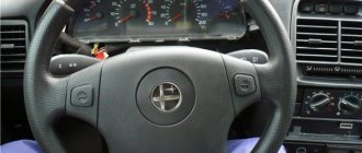
The Chevy Niva has a very nice and convenient steering column switch compared to VAZ cars of the ninth and tenth families. It not only looks better, but also works quieter, and the key strokes are shorter than those of the “nine”. Accordingly, it has softer shifts, which is why craftsmen immediately began installing this product on other Lada cars. In some cases, the replacement is quite simple, in others, electrical skills will be required.
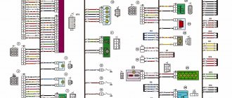
Electrical diagram of VAZ-21213
1. Headlights 2. Side turn signals 3. Windshield washer motor 4. Headlight washer motor *. 5. Switch 6. Battery 7. Starter VAZ-21213.8. Generator 9. Headlights 10. Headlight washer gear motors *. 11. Horn 12. Spark plugs 13. Carburetor limit switch 14. Carburetor solenoid valve 15. Ignition coil 16. Windshield wiper motor 17. Carburetor solenoid valve control unit 18. Ignition distributor 19. Coolant temperature sensor 20. Oil pressure indicator sensor 21 .Portable flashlight ** 22. Insufficient brake fluid level indicator sensor 23. Windshield wiper relay 24. Rear fog lamp activation relay *** 25. Rear window heating element activation relay. 26. Relay for turning on headlight washers and washers *. 27. Low beam relay 28. High beam relay 30. Starter relay 31. Hazard and turn signal switch relay 32. Electric heater motor 33. Additional resistance of the electric heater motor 34. Lighting indicators for the heater control levers 35. Exterior light switch. 36. Main fuse box 37. Additional fuse box 38. Reversing light switch 39. Brake light switch 40. Instrument lighting control 41. Ignition switch 42. Three-lever switch 43. Alarm power switch 44. Headlight and headlight washer switch 45. Switch heater electric motor 46. Rear window resistance switch 47. Rear fog light switch 48. Light switches are located in the door shelves 49. Interior lamps 50. Cigarette lighter VAZ-21213.51. Carburetor choke warning lamp switch 52. Carburetor choke warning lamp 53. Differential lock warning lamp switch 54. Parking brake warning lamp switch 55. Fuel level and reserve sensor 56. Instrument cluster 57. Rear windshield washer motor 58. Tail lights 59 Block for connecting additional brake lights 60. Blocks for connecting side sensors 61. Blocks for connecting to the rear window heater 62. License plate lights 63. Rear window wiper motor.
The order of conditional numbering in blocks: A - windshield wipers for headlights and rear window, windshield wiper relay switch; B — ignition distributor sensor; B - signal relay switch and turn signals; G - switch; D - three-lever switch; E - hazard warning switch; W — relay for turning on rear fog lights; Z — rear lights; E - instrument cluster VAZ-21213.
In the dashboard wiring, the second ends of the white wires are brought together into one point, which is connected to the dimmer of the device. The other ends of the black wires are also connected at a point connected to ground. The other ends of the yellow wires with the blue stripe connect at a point connected to the "A" terminal of the main fuse box. And the second ends of the orange wires are also connected at the point connected to the "B" terminal of the main fuse box.
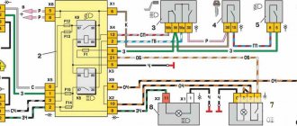
VAZ ignition switch pinout
The ignition switch in cars of the VAZ family fails from time to time due to weakening of the contact posts or burning of the contacts inside it. It also happens that the cams of a plastic roller are produced. You can disassemble the lock and clean it, but it’s better to just replace it with a new one, considering that it costs pennies compared to imported locks.
But if connecting the wires together did not result in the starter operating (or it did not turn on the first time), check the solenoid relay on the starter. The contact spots on it may also burn out, which will prevent the circuit from closing normally. Alternatively, you can use a screwdriver to short-circuit the two large terminals on the solenoid relay (before doing this, put the car in neutral and use the handbrake). When closed, the starter should begin to spin vigorously. If this happens, remove and change the solenoid relay. If the starter rotates “sluggishly” when it closes, you will have to remove it and check the condition of the brushes.
All operations are performed with your own hands, without the help of car service specialists. Moreover, the price of an ignition switch on a VAZ2106 is up to 100 rubles. To replace it, you will need to know the pinout of the wires coming from it, for which the editors of the site 2 Schemes.ru have prepared a large reference material.
The ignition switch is designed not only to start the engine - it performs several functions at once:
The second version of the NIVA 21213 scheme
1. Headlights 2. Lights 3. Wiper motors 4. Horn 5. Headlight washer motor 6. Windshield washer motor 7. Alternator 8. Side turn signals 9. Battery 10. Heater motor 11. Heater motor auxiliary resistance 12. Relay -windshield wiper switch 13. Snack 14. Wiper motor 15. Carburetor limit switch 16. Carburetor solenoid valve 17. Carburetor solenoid valve control unit 18. Switch 19. Spark plugs 20. Ignition distributor sensor 21. Oil pressure warning lamp sensor 22. Indicator sensor temperature 23. Portable lamp socket 24. Ignition coil 25. Brake fluid level in the sensor warning lamp 26. Headlight washer and headlight washer ignition relay 27. Rear window heating relay 28. Headlight high beam relay 29. Headlight low beam relay 30. Ignition relay on 31. Starter switch relay 32. Differential lock warning lamp switch 33. Exterior lighting switch 34. Cigarette lighter 35. Brake light switch 36. Reversing light switch 37. Turn signal and hazard warning relay switch 38. Main fuse box 39. Additional fuse block 40. Heater control lamps, 41. Rear fog light switch 42. Rear window defroster switch 43. Heater motor switch 44. Rear window wiper and washer switch 45. Hazard light switch 46. Power switch 47. Control panel carburetor choke lamp 48. Lighting switch 49. Three-lever switch on the steering column 50. Carburetor choke warning lamp switch 51. Rear windshield washer motor 52. Ceiling switches located in the door shelves 53. Internal lampshades 54. Instrument panel 55. License plate lights 56. Parking brake warning lamp switch 57. Level indicator and fuel reserve sensor 58. Tail lights 59. Rear window wiper motor 60. Rear window resistance 21213.
Installation of steering column switches Shniva, lock VAZ2110
Installation of steering column switches Shniva, lock VAZ2110
Post by Parshmak1 » Sep 20, 2011, 12:22 pm
Hello. Below I describe the installation of a Kalina-type steering wheel, Chevrolet Niva steering column switches, and a VAZ2110 wiper motor.
Preparing for installation. 1. Steering wheel.
It is necessary to remove the squeegee from the steering wheel by pulling it towards you, first from the top, then from the bottom.
On the back of the steering wheel you can see black plastic with a copper ring. This plastic snaps onto the steering wheel. We remove the plastic mask, because we don’t need it.
I see no point in repeating myself. In this case, the steering wheel lock will not work.
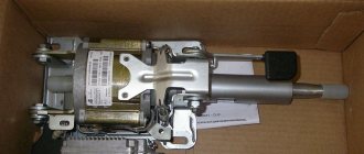
2. Since we are not looking for easy ways, we will go with the second option. The goal is for the steering wheel to work, so that the steering shaft bearings are made of steel and not rubber, and so that the steering wheel does not wobble. Remove the old ignition switch.
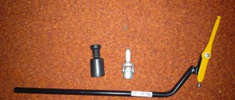
Stage 1. Preparing the tube (sorry, but I don’t know what it’s called correctly) of the steering column. 1. Remove the old rubber bearings. The photo shows that the edges of the tube are bent so that the rubber bearings do not fall out. We bend the edges and knock out the shaft with bearings.
2. We cut a hole for the future lock 2110. It is necessary to cut a hole measuring 20X25 mm with a grinder, retreating 20 mm from the edge of the tube. Cut the hole on the right side as I indicated in the photo. On the steering column (on the left side) there is a rectangular cutout for the tongue of the old ignition switch. This cutout should be your guide. Those. cut a new hole strictly on the reverse side of this rectangular cutout. Otherwise, the ignition switch will be crooked) I hope I explained it clearly.
Additional schemes
Diagram for switching on direction indicators and hazard warning lights
1 — direction indicators in the headlights; 2 — side turn signals; 3 — ignition switch; 4 - ignition relay; 5 — fuse block VAZ-21213; 6 — direction indicators in the rear lights; 7 - control pump for direction indicators in the instrument panel; 8 — relay switch for direction indicators and hazard warning lights; 9 — alarm switch; 10 — direction indicator switch.
External lighting switching diagram
1 — side lights in the front lights; 2 - fuse block; 3 — external lighting switch; 4 — instrument lighting switch; 5 - indicator lamp for external lighting in the instrument panel; 6 — license plate illumination; 7 — side lights in the rear lights; A - to the illumination of the instrument cluster, switches and display illumination of the VAZ-21213.
Connection diagram for carburetor solenoid valve control system
1 — ignition switch VAZ-21213; 2 - ignition relay; 3 - ignition coil; 4 — control unit; 5 - solenoid valve; 6 — carburetor limit switch.
Let's finally return to the implementation of large plans. Leafing through the in-flight magazines, I collected a bunch of different options for modifying the steering column switches, which at the same time forced me to modify the ignition switch on the right side and replace the wiper motor gearbox. My conversion took several months and the car is always at hand. I’m not the first, so I’ll briefly describe the nuances so as not to make any mistakes. First you need to stock up on the “ingredients”: 1. Steering column switches for the Shniv or Kalina assembly (consist of the right, left and middle parts, I came across Shniv ones for 650 rubles) 2. Connector covers on the steering column, 3. Ignition switch (maybe the tenth one, you can use a chisel, if the lock has a relay, then take a more powerful five-pin relay of about 40A, because the weak one sticks at the most inconvenient moment), 4. The mating part of the connector for the lock, 5. Pulls for the steering column trim (remove the fasteners from the casing, rubber ring under the ignition switch 10), 6. The tenth gearbox of the wiper motor (on the plastic cover 842-3730 select the designation, it has a slot and the fasteners exactly fit the original stage lever, I took it apart for 300 rubles), 7. The mating part of the connector to motor, the mating part of the windshield wiper relay connector (original 4 pins, but 6 are needed), 8. Windshield wiper relay 10th, there is no difference in the chisel, I found one to suit my taste and a wallet for 90 rubles. (best with an adjustable pause), 9. A handful of connectors for mothers, heat-shrink tubing to their size or electrical tape, soldering iron. 10. A piece of hydraulic hose with a diameter of 40 mm, a large clamp for climbing on it with a reserve, 11. Cables for construction and laying new ones, 5 meters.
Our job is to take the grinder and cut, cut, cut. But seriously, we remove the steering wheel, remove the steering column cover, the steering column switch (after cutting off the wires from it for the same rape). We put the ignition switch on the steering column body, glue it so that it can move along the body. We apply the steering column cover, resting against the dashboard and centering it relative to the steering shaft. We align the ignition switch with the hole in the steering housing and secure it. Then remove the cover and use a sharp tool to mark the position of the ignition switch on the steering column housing. We will need these marks to cut a hole for fixing the steering lock.
On the ignition switch, where the steering lock tongue comes from, there is a rectangular protrusion; you need to drill a hole for this protrusion with a grinder. But first we unscrew the steering column housing, closer to the seat there are two bolts of 13 or 14 and closer to the engine shield two bolts with round heads, which need to be unscrewed with a sharp chisel or a rod and a hammer. Then unscrew the bolt by 13, fixing the steering shaft clamp where the grooves enter the cardan. We remove the steering shaft from the steering housing, having first removed the rubber bearing (pay attention to the bearing, the cylinders may fall out of it). A hole was drilled in the steering housing for the ignition switch. A cylinder with a groove for the steering wheel locking tongue is welded to one side of the steering shaft. We fix the shaft in a vice and use a grinder to cut the weld seam between the cylinder and the shaft. We move the cylinder along the shaft to a new place where the ignition switch will be fixed and weld it. Reassembling everything in reverse order, we put the ignition switch on the steering housing. We remove the connector block from our ignition switch, take out the wires from it and insert these wires into the block of 6 connectors according to the connection diagrams (the colors of the wires are almost the same), turn the key and see what works and what doesn’t, correct errors.
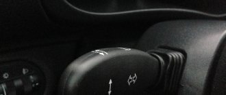
The steering column switch is mounted on the steering shaft bracket.
The switches on the left control the turn signals (short) and headlights (long), while the switches on the right control the windshield wipers and windshield wipers. (The rear wiper and washer are activated by a button on the dashboard.)
Modification of the steering columns on the VAZ 2110
Refinement of steering columns
If the driver is not interested in the replacement process itself, but only needs to eliminate the clicking of the steering column switches, then we can advise simply carrying out modifications.
Eliminating clicks
So:
- We remove the switches from the VAZ 2110. Usually, no difficulties arise in this process.
- We disassemble the steering columns by snapping off the top cover with a screwdriver (small size).
- We find a small slide inside the switch (it is this that is responsible for the loud switching).
- Now you need to find a suitable rubber, for example, a car door seal (old and no longer needed). This very piece of rubber will need to be glued to the points of contact between the scenes.
Advice. To make the switching happen more smoothly, it is recommended to slightly file the plastic bump. We try to make the tip more rounded, otherwise it will jump. If this cannot be done, then you can use another method: weaken the spring.
- Let's put everything back together.
- We cover the switch body with some kind of vibration material. It is recommended to do the same with the steering shaft casing.
Closing the openings of the steering column switches
Openings can be closed easily and simply
Sitting behind the wheel of a VAZ 2110, you cannot help but notice the large gaps located near the steering column switches. This looks very unaesthetic and not at all practical. Let's try to close them:
- Take a piece of black carpet.
- We cover the steering column switch with Moment glue.
- We wait until the required time dries.
- We glue the carpet directly onto the steering column switch, closing the gap.
Note. It is not necessary to use only carpet. If you don’t have it, then you can take a piece of modelin or even an old felt boot.
You can easily replace the switch yourself, following the instructions. Thus, it will be possible to save the price of services in specialized workshops. During the work process, it is recommended to study photo and video materials.
The structure of a car ignition switch
The lock mechanism is connected to many wires. They continue from the battery, connecting all the electrical devices of the car into a single chain. When you turn the ignition key, the electrical circuit is closed from the “-” terminal of the battery to the ignition coil. As a result, the current passes through the wires to the ignition switch, through its contacts it is directed to the induction coil, after which it returns back to the “+” terminal. As electricity passes through the coil, it generates high voltage, which it transmits to the spark plug. Therefore, the key closes the contacts of the ignition circuit, thereby starting the car engine.
Pinout of the ignition switch VAZ-2101 - VAZ-2107
The ignition switch on these cars is located to the left of the steering column. It is fixed directly to it using two fixing bolts. The entire mechanism of the device, except for the upper part in which the keyhole is located, is hidden by a plastic casing.
On the visible part of the ignition switch housing, special marks are applied in a certain order, allowing inexperienced drivers to navigate the lock activation mode when the key is in the hole:
The ignition switch has five contacts and, accordingly, five terminals, which are responsible for supplying voltage to the desired unit. All of them are numbered for convenience. Each pin corresponds to a wire of a certain color: