The steering column switch is a long-standing problem with front-wheel drive cars. Lada Kalina was no exception and therefore it is difficult to avoid breakdowns in this regard. More often steering column switches Lada Kalina They break down gradually, let's say.
When driving with the low beams on, the high beams will occasionally turn on and flash. If you find such a problem, you need to replace the switches. You can do this yourself. However, if the replacement did not help much, the best solution would be to turn to a professional.
Important! The list of tasks of the steering column switch includes not only controlling the headlights, but also the washers, wipers, turn signals and the on-board computer as a whole.
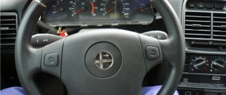
Steering column switch Kalina with joystick
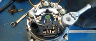
The Lada Kalina steering column switch block consists of a base secured with a clamp to the steering gear shaft bracket and two multi-position switches. The left switch on the car turns on the turn signals and switches the headlights, the right switch controls the windshield washer and wiper. All possible positions of the switch levers are shown in Fig. 1, the contacts closed in this case are indicated in table. 1.
The photo above shows the contact numbers of the turn signal and headlight switches. (left switch)
The photo above shows the contact numbers of the wiper and washer switch (right switch)
Rice. 1 Possible options for turning on the steering column switch levers of the Lada Kalina (Two trip computer control buttons are built into the right switch lever - optional)
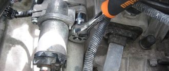
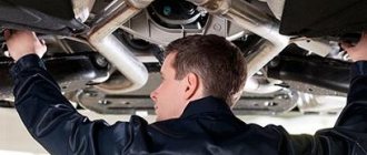
To remove the steering column switches, you will need an 8 mm wrench and a Phillips and flat-blade screwdriver.
LADA (VAZ) cars
Repair manual for VAZ 2110-2112, Lada Priora, Kalina
- Possible malfunctions of lighting and light signaling, their causes and solutions
- Design Features
- Replacing lamps
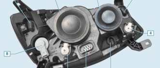
- Replacing the headlight
- Replacing the side turn signal light
- Replacing the rear light
- Replacing an additional brake light
- Replacing the license plate light
- Removing and installing the interior lamp
- Replacing the control unit for external lighting and instrument lighting
- Checking and replacing steering column switches
- Removing, installing and adjusting the sound signal
- Table of contents
- 10. Electrical equipment
- Lighting, light and sound alarm
Preparation for replacement and necessary equipment
To replace the old switch you will need a Phillips screwdriver, a dry, clean cloth or thick napkins. And, of course, a new detail. Before changing the Kalina steering column switch , you have to carefully get to it, since such procedures are usually carried out rarely. Don't forget to disconnect the negative battery terminal.
The first stage of preparation is removing the steering wheel. First, move it to the lowest position. Using a Phillips screwdriver, carefully unscrew the 7 fasteners of the plastic casing. We remove first the lower and then the upper part.
The second stage is dismantling the old switch. It does not include anything complicated - you don’t even need tools, everything is attached with latches. For example, we will take the right lever, which is responsible for the on-board computer and wipers. Disconnect the small plug with the wires by pressing the latches and pulling towards you. Now, guided by the same principle, we pull out the large plug. You may have to make an effort here.
We see the steering column switch, which is held on by clamps. We clamp them and pull the lever towards ourselves. The other levers are removed in exactly the same way. The only thing worth mentioning is that they can be held by fewer or more plugs.
Required tool: Phillips screwdriver.
- Remove the lower screw and upper self-tapping screw connecting the upper and lower steering column housings on the left side.
- And then on the right side.
- Lower the steering column adjustment lever down and remove the upper steering column cover.
- Unscrew the 3 screws securing the lower casing.
Removing the plastic cover under the steering wheel:
- First of all, lower the steering wheel to the lowest position
- Take a Phillips screwdriver and unscrew all the casing mounting bolts, of which there are only 7 pieces
- The side ones are located at the very top on the right and left sides, one at a time:
- Now you need to unscrew the bottom bolts, three of which are shown below:
- And two are also below, at the very end:
- After which you can carefully remove the casing, first its lower half, and then the upper
With this all done, you can now proceed directly to replacing the steering column switches.
How to check the lighting devices in the Chetyrka?
The verification procedure is carried out as follows:
- First you need to make sure that you are using a working fuse. The fuse box is located in the engine compartment, in the compartment between the engine and the windshield, opposite the driver's seat. Bend the latches and remove the cover, then carefully inspect the inside. It contains a diagram that will help you figure out which fuse is responsible for the operation of a particular equipment. Remove the fuse responsible for the functionality of the software and carefully inspect it - if the fuse inside is melted or damaged, the fuse must be replaced. But even if there is no visible damage, you need to insert another one with the appropriate rating into the socket of the removed fuse.
- If this does not help restore the software, then check the relay, it is located in the same block. Typically, the turn signal relay has a hazard warning symbol on it, you need to pull it out and replace it with a working one. To do this, it is not necessary to buy a new relay; you need to pull out another working device and install it. If the emergency lights and software do not work, then we continue checking.
- Now we need to diagnose the light bulbs, but such a check will be required if only part of the turns does not work. Open the hood or trunk and remove the headlight protection, then remove the light sources from their seats. Install a known working device in place of the removed lamp and check how it works. If there are no changes, we move on.
- It is necessary to check the integrity of electrical circuits. To do this, you will need a test lamp with two wires connected to it. One end should be connected to the negative of the battery or the body of the Four, and the second wire is connected to the contact of the electrical circuit being diagnosed. If, as a result of the connection, the lamp begins to light, this indicates that the section of the wire being tested is in good condition. The remaining circuits are checked in the same way. If you find a place where there is no current, then this indicates that there is a fault between the place being tested and the last point where the voltage was. Damaged wires must be replaced.
- You also need to check the quality of contacts on all electrical circuits. Check the contacts in the mounting block, on the base in the vehicle's optics, on the light alarm button and on the steering column switch. Often the cause of problems is oxidation; such contacts must be cleaned or replaced.
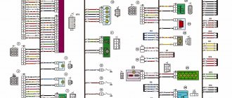
General diagram of VAZ-1117, VAZ-1118, VAZ-1119
Elements of the instrument panel harness connection diagram
1, 3, 4, 5 — blocks of the tidy wire bundle to the front harness; 2, 8 - the same for the rear “pigtail” of wires; 6, 7, 9, 10 - continuation of the direction to the assembly unit; 11 — power supply for the lighting control device; 12 — set of instruments; 13 — toggle switch for the electric motor of the stove; 14 — power supply to the air supply box; 15 — ignition switch Lada Kalina; 16 — immobilizer block; 17 — block of the dashboard wiring harness to the ignition system wire bundle; 18 — cigarette lighter power supply; 19 — alarm switch; 20 — rear window heating switch; 21 — brake light switch; 22 — alarm light breaker; 23 — adjustment of computer modes; 24 — windshield wiper control; 25 — VAZ horn switch; 26, 27 — heating and ventilation control lighting lamps; 28 — glove box lighting; 29 — power supply to the on/off button in the glove compartment; 30, 31 — pinout for the standard radio; 32 — power supply to the electric motor of the stove; 33 — heater resistor network; 34 - electric amplifier control unit.
Steering column switches Lada Kalina
The steering column switch is a long-standing problem with front-wheel drive cars. Lada Kalina was no exception and therefore it is difficult to avoid breakdowns in this regard. Most often, the steering column switches on the Lada Kalina break down gradually, let’s put it this way.
When driving with the low beams on, the high beams will occasionally turn on and flash. If you find such a problem, you need to replace the switches. You can do this yourself. However, if the replacement did not help much, the best solution would be to turn to a professional.
Important! The list of tasks of the steering column switch includes not only controlling the headlights, but also the washers, wipers, turn signals and the on-board computer as a whole.
- Preparation for replacement and necessary equipment
- Replacement and assembly
- Lada Kalina steering column switch connector and its replacement
- Bottom line
Removing and installing high beam, turn and wiper switches:
This does not require any tools, since everything is attached with latches and can be changed in just a few minutes. As an example, I will show everything on the right lever, which is responsible for the wipers and on-board computer.
- The first thing you need to do is disconnect the small plug with the wires, just press the two plastic latches along the edges and pull it towards you:
- Now you need to disconnect the large plug from the switch, it does not have any locks, just apply a little force and pull it to the side:
And now you can safely remove the steering column switch itself, for which you just need to press the latches on the sides and pull the lever towards you:
- It is easily removed and the left one, which is responsible for high beams and turns, is removed in the same way, even easier, since there is only one plug. The removed lever is shown in the picture below:
After this, we install a new switch in place of the failed one, replacement is carried out in the reverse order of removal.
The steering column switch is a long-standing problem with front-wheel drive cars. Lada Kalina was no exception and therefore it is difficult to avoid breakdowns in this regard. Most often, the steering column switches on the Lada Kalina break down gradually, let’s put it this way.
Lada Kalina steering column switch connector and its replacement
Remove both switches as described above. Now, if the car has an airbag, you need to disconnect the block with wires from the slip ring.
The connector can be removed along with the slip ring, but it is better to describe the complete disassembly process. Therefore, to remove the ring, unscrew the nuts using a screwdriver. You should be careful here, since the slip ring is a very delicate element of a balanced system. If you turn something incorrectly or roughly, there is a chance of disturbing the centralization of the ring during assembly.
Next, you need to disconnect the horn wire block. Use an 8 mm socket to loosen the tension and calmly remove the connector.
We install a new connector for the steering column switches. Next, we carefully assemble the system:
- Tighten the bolt with an 8 mm socket very gently;
- We install the connector in a position in which the central fastening screw of the lower masonry could be screwed in;
- We install the lower masonry in its rightful place and adjust the position of the connector;
- When the desired position is found, remove the bottom cover and, without moving the connector, tighten the fasteners;
- Next, we assemble the system using the reverse principle in relation to disassembly.
Snail installation
When reassembling, the front wheels must be aligned and the rotating contact plate must be locked in the middle position by the safety lock. For this:
- we determine the maximum number of revolutions of the contact disk (No. 2) by rotating it from the extreme left to the extreme right position (without using force);
- turn the contact disk to the middle position, counting half the maximum number of revolutions from the extreme position;
- align the holes (No. 4) for the fuse on the disk and the hole (No. 5) in the body of the rotating device and install the fuse (No. 6).
The screw tightening torque is 1.6…2.4 N.m (0.16…0.24 kgf.m).
Let us remind you that the website contains other instructions for servicing and repairing Vesta or XRAY with your own hands. The necessary information can be easily found using the search (in the upper right corner of the site) or by content (Vesta, XRAY).
Front door diagram Kalina 2
| 1 – block of the wiring harness of the front left door to the block of the rear wiring harness; 2 – electric window lift motor; 3 – front left lock; 4 – driver’s door module; 5 – front left loudspeaker; 6 – left mirror. | 1 – block of the wiring harness of the front right door to the block of the rear wiring harness; 2 – electric window lift motor; 3 – right front lock; 4 – power window switch; 5 – front right loudspeaker; 6 – right mirror. |
Light control module diagram (LCM) Kalina 2
| A1 - external lighting switch; A2 — rear fog lamp switch; A3 — control device for rear fog lights; A4 - front fog lamp switch; A5 - control device for front fog lights; A6 - device for turning on side lights; HL1, HL2 - LEDs for illuminating the pointer and outdoor lighting symbol; HL3 ... HLn - LEDs for illuminating symbols (symbols). | 1 + 12V. (Taken from the central unit, the signal for turning on the dimensions). 2 To the rear fog lights. 3 To the front fog lights. 4 To daytime running lights. 30 + 12V to generator terminal (30) 31 Housing. 56 To low beam headlight lamps. 58 To the side lights and the circuit of illumination sources. Xz To the ignition switch (+ 12V, terminal 15). |
Ignition circuit Kalina 2
1 – oil pressure warning lamp sensor; 2 – generator; 3 – throttle pipe with electric drive; 4 – coolant temperature sensor; 5 – ignition system wiring harness block to the instrument panel wiring harness block; 6 – solenoid valve for purge of the adsorber; 7 – air conditioning system pressure sensor; 8 – mass air flow sensor; 9 – crankshaft position sensor; 10 – oxygen concentration sensor; 11 – controller; 12 – diagnostic oxygen concentration sensor; 13 – blocks of the wiring harness of the ignition system and the wiring harness of the ignition coils; 15 – ignition coils; 16 – spark plugs; 17 – nozzles; 18 – blocks of the wiring harness of the ignition system and the wiring harness of the injectors; 19 – phase sensor; 20 – knock sensor.