Manufacturers and prices of analogues
Analogs include frame, frameless, and hybrid brushes.
There are several options on the market. Choose the one that suits you best - no matter whether it has a frame or not. The main thing is not to let the old windshield wiper start to scratch the windshield or rear window. When replacing cleaning brushes, use the following dimensions in millimeters (driver - passenger side):
- 630 – 480;
- 530 – 510;
- 510 – 500.
Other layouts are considered by car owners to be not as effective. Among the well-known analogs of windshield wiper blades are:
- Bosch Aerotwin - frameless, made in Belgium. Full name: Bosch aerotwin retrofitar 532 s. Price – 1200-1300 rubles. The length of the driver's seat is 53 cm, the passenger's length is 50 cm. Sold as a set.
- Bosch Twin is a simpler model. They have the same dimensions, but despite the lower price they are famous for their reliability. The cost is about 800 rubles.
- Bosch Eco is the most economical option. They are inexpensive and sold individually. Price – 300 rubles for one brush. Length – 50 cm.
- Denso Hybrid is recognized as almost the best model on the market. Withstands cold and heat. Price per piece – 500 rubles. Length 50 cm.
- Alca - simple, 500 rubles apiece. The length is 50 cm, but on the passenger side an area of approximately 5 cm wide is left uncovered.
Read more: Which timing belt is better to choose from the manufacturer?
Designations for the rear wiring harness of the VAZ Priora
The wiring harness, located in the passenger compartment and rear of the car, has the shape of a flexible barrel with branches on which contacts are installed with blocks for docking with consumer electrical appliances. The rear electrical circuit is also connected to lighting fixtures, locks, power windows, front and rear doors.
The pinout of tips and terminals looks like this:
| Contact no. | Decoding |
| 1 | Dashboard |
| 2 | Left rear door wiring harness block |
| 3 | Right front door wiring harness block |
| 4 | Used double-glazed windows and door locks |
| 5 | Left turn signal |
| 6 | Right turn signal |
| 7 | Interior lighting module |
| 8 | Handbrake warning lamp switch |
| 9 | Left side light |
| 10 | Right side lamp |
| 11 | Interior temperature sensor |
| 12 | Interior light switch in the left front door pillar |
| 13 | Interior light switch in the front right door pillar |
| 14 | Interior light switch in the right rear door pillar |
| 15 | Interior light switch in the left rear door pillar |
| 16 | Driver's door wiring harness |
| 17 | Right rear door wiring harness |
| 18 | Rear right speaker |
| 19 | Rear left speaker |
| 20 | Cigarette lighter |
| 21 | Fuel pump block |
| 22 | Trunk light switch |
| 23 | Rear window heating device |
| 24 | Trunk light |
| 25 | Additional brake light |
| 26 | Tailgate lock switch |
| 27 | License plate lamp harness |
| 28 | Right front door harness block |
| A 1-A4 | Grounding |
| XP, XP3 | Electrical package power controller connectors |
The rear wiring harness is marked 2170-3724210.
Lada Kalina steering column switch connector and its replacement
Remove both switches as described above. Now, if the car has an airbag, you need to disconnect the block with wires from the slip ring.
The connector can be removed along with the slip ring, but it is better to describe the complete disassembly process. Therefore, to remove the ring, unscrew the nuts using a screwdriver. You should be careful here, since the slip ring is a very delicate element of a balanced system. If you turn something incorrectly or roughly, there is a chance of disturbing the centralization of the ring during assembly.
Next, you need to disconnect the horn wire block. Use an 8 mm socket to loosen the tension and calmly remove the connector.
We install a new connector for the steering column switches. Next, we carefully assemble the system:
- Tighten the bolt with an 8 mm socket very gently;
- We install the connector in a position in which the central fastening screw of the lower masonry could be screwed in;
- We install the lower masonry in its rightful place and adjust the position of the connector;
- When the desired position is found, remove the bottom cover and, without moving the connector, tighten the fasteners;
- Next, we assemble the system using the reverse principle in relation to disassembly.
Pinout of Kalina steering column switches is a simple matter for a person who has at least once taken on the task of repairing or at least disassembling the steering column space. Be careful and don't be overconfident.
We recommend watching:
- What type of spray gun is needed to paint a car?
- Spray gun for all types of painting
- Priora steering column switches for VAZ 2110
- How to Draw Fine Lines with an Airbrush
- What kind of cylinder is needed for semi-automatic welding
- DIY truck frame repair
Replacing the steering column switch in a VAZ 2110 yourself
How to replace the steering column switch on a VAZ 2110
Replacing the steering column switch in a VAZ 2110 is carried out for the following reason: this element of the car is not as beautiful and functional as on foreign cars. On a VAZ 2110, replacing the steering column switch can be easily done on your own. You just need to follow the instructions and do everything in accordance with it.
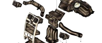
Cooling
Water Pump (Pump), Water Pump (Pump) Pulley, Water Pump (Pump) Gasket, Intercooler, Intercooler Hose, Thermostat, Thermostat Housing, Thermostat Gasket, Radiator Fan, Fan Assembly, Inverter Fan, Diffuser, Fan Motor, Fan Relay, Viscous coupling, Impeller, Air conditioning, Air conditioning compressor, Compressor bearing, Compressor pulley, Pneumatic switch, Air conditioning dryer, Air conditioning pipe, Air conditioning control unit, Interior temperature sensor, Air conditioning evaporator, Thermostatic valve, Air conditioning mount, Air conditioning resistor, Air conditioning relay, Air conditioning hose, Radiator, Cooling radiator, Radiator mounting, Radiator hose, Coolant sensor, Air conditioner radiator, Inverter radiator, Radiator pipe, Adapter flange, Expansion tank, Expansion tank cap
Replacement and repair of the electrical package control unit 2170-3763040 Lada Priora
Priora electrical package control unit 2170-3763040 (Comfort unit) The vehicle equipment, as is sometimes written, does not matter when a unit with this number is installed.
The electrical package controller is a device designed for installation on VAZ 2170 Priora cars. It controls many car functions, for example, turn signals, power windows, instrument panel lights, side lights, low beam, fog lights, reverse lamp, interior lighting, heated rear window.
This controller is installed in the central, lower part of the dashboard above the ECU unit. To remove it, you need to remove the lower sides of the torpedo. Using a socket wrench 10, unscrew the two nuts.
Priora electrical package control unit housing 2170-3763040
Priora electrical package control unit board 2170-3763040
Location of terminals of the Priora electrical package control unit 2170-3763040
Diagram of the Priora electrical package control unit 2170-3763040
Purpose of parts on the board of the Priora electrical package control unit 2170-3763040
POS - interior lighting lamp ZPTO - rear fog lights BS - low beam PTF - fog lights MDV - driver's door module PUP - turn signal switch PAS - hazard warning switch PPD - front right door PLD - front left door ZPD - rear right door ZLD - rear left door PS - passenger door power window switch FOB - trunk light ZP - right mirror ZL - left mirror GO - side lights UP - direction indicators
At this link you can see additional information on the above unit and others: www.chiptuner.ru/content/usp_norma Problem with the electrical package control unit 2170-3763040 Priora:
Priora electrical package control unit 2170-3763040 old
After turning on the heated rear window, a malfunction occurred in the operation of this unit. The IMMO started flashing, the emergency lights came on - it’s impossible to turn it off. After turning off the heating, the turn signals and emergency lights, mirrors stopped functioning, the central locking stopped working, both from the key and from the buttons in the cabin, the tidy went out, and the power windows stopped working.
A new electrical package control unit 2170-3763040 Priora was installed:
Electrical package control unit 2170-3763040 new
The procedure for removing and installing the block is simple. There is no need to retrain the key, everything works. The only thing is that the two-level door opening system stopped working. Now one click opens two doors. or one press and only the driver's door opens, a second press and the passenger door does not open... Strange.
Repair of the electrical package control unit 2170-3763040 Priora: In the old unit, for the sake of experiment, two VN5016AJTR-E power driver microcircuits (SSO-12) were replaced
Resoldering the VN5016AJTR-E chips did not bring any results.
Resoldered chip: MCZ33972EW
Chip MCZ33972EW for replacement.
Replacing the turn switch for a VAZ 2110
A possible replacement of the VAZ 2110 turn switch can be done for a variety of reasons. Owners install new steering column switches even from the standpoint of improving their appearance and changing functionality. When using faulty switches, do not forget about the safety of driving. Even turning off a turn at the wrong time can lead to an emergency.
Functional purpose and possible malfunctions The left steering column switch, which is connected to a contact group located in the control unit, is responsible for the operation of external lighting devices.
Along with the aesthetic component, long-term use of the 10th model can lead to some problems with the functioning of the turn switch:
• uncontrolled switching of low beam to high beam; • failure to return the turn signal lever to its previous value; • hard shifting, sticking, broken shift lever.
Despite the fact that the levers have some disadvantages, their simple replacement and convenient location for the driver make the option of installing new original parts a more preferable option.
Replacement procedure
To quickly and efficiently replace the VAZ 2110 turn switch, you must strictly follow the sequence of operations.
To begin work, disconnect the negative terminal from the battery. Next, perform the following operations:
• release the fastening of the upper and lower parts of the steering column casing by unscrewing two screws each in the lower and upper parts;• unscrew the screw securing the steering column switch block to the casing;• unscrew the screws securing the lower part of the casing to the steering column bracket;• disconnect the connector of the steering column power wiring harness switch; • holding the clamps, remove the steering column switches on each side.
If the device is planned to be replaced with an original part for this model, then further repairs involve the installation of a new unit and reverse assembly operations. In some cases, for example, when it is necessary to replace the VAZ 2110 turn switch together with the windshield wiper control unit, the connector is also removed. To do this, you must additionally disconnect the power wires for the sound signal.
If you plan to install a switch block from another model, for example, from a Lada Priora, then you should pay attention to some points: • matching of the contact connector when connecting; • location of the levers in relation to the steering wheel. Despite the best functionality, various combinations have some disadvantages. For example, when installing levers from a Priora, it is impossible to turn on the right turn signal when the headlights are in high beam mode. When installing a steering wheel from a Lada Kalina with a switch block, such work is more expensive, and the steering wheel cover does not fit
autochauffeur.ru
Steering columns from Kalina, Priora and Chevy Niva
Note. On the VAZ 2110 you can easily and simply install switches from Lada Kalina, Chevrolet Niva or some foreign cars.
Features you need to know about
Replacing the steering column switch for a VAZ 2110
Let's look at some features of steering column switches from other cars that we want to install in the VAZ 2110:
- The main thing is the connector, which must match the VAZ 2110 and then there will be no problems.
- It is also recommended to pay special attention to the shape of the switch. For example, the steering column shifters from the Priora become further from the steering wheel than the tenth shift paddles. In this case, you have to lengthen the steering shaft or install another one from the same Kalina.
Steering column switches VAZ 2110
Note. There is another way: bend the steering column switch and cut off the excess part, and then glue it at a different angle, but this is not entirely correct. We need to think about safety, but a glued-on steering column does not fit in with this. Therefore, if we change the steering columns from Priora, Kalina or Niva, we will have to put up with a large distance of levers.
Conventional DIY installation of steering column stalks
- Disconnect the positive wire from the battery.
- Now remove the lower steering column casing by unscrewing the 7 fastening screws.
- Lower the steering column down.
- Remove the upper steering column casing.
VAZ 2110 replacement of steering column switches
- We find two plastic clips and squeeze them to remove the windshield wiper switch (see Replacing windshield wipers on a VAZ 2110 on your own) from the base.
- Disconnect the block with wires.
- We now remove the turn signal and headlight switch, again, squeezing the two plastic clips.
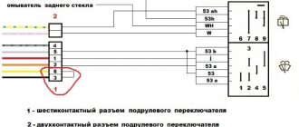
Connection diagram and setup
In the basic instructions, Starline provides a diagram for the A91 model:
Shown here is the harness going to the dashboard. Let's figure out what is connected where:
- The diode connected to the wire break must conduct current in the direction “towards the limit switches”;
- Above we talked about the 1N5401 diode;
- The second diode connected to the alarm wire may be designated 1N4001 (it is cheaper).
Now let's look at what is in the second bundle, located under the first:
From the two blue cables shown above, make T-shaped bends and extend the cords to the alarm installation location. And a 1N4001 diode is installed in the gap in the handbrake wire. The cathode of this diode “looks” towards the switch. Finally you will make the connections:
- The “green-yellow” and “green-black” wires from connector X3 are connected to the turn signal leads.
- Another tap coming from the cathode is connected to the “brake input” of the Starline A91 Dialog signaling system. The cord is designated as “orange-purple”.
It was discussed how to connect all the signal wires with your own hands. Queue for the security forces.
The steps listed in this chapter can be completed before installing the alarm. The functionality of standard equipment should not be affected.
Connecting the autostart connector
In VAZ 2114 cars, unlike the “nines”, an ignition switch with three terminals is used: 50, 15 and 30. The latter is connected to the battery, and contact 15 closes with it when the key is turned. Well, the 50th terminal is the “output "to the starter. Similar designations are used not only by VAZ.
As for model 2114, the lock escutcheon is secured with three self-tapping screws, as well as three metric screws. Unscrew them and you will see the following:
According to the basic instructions, power for the signaling can be taken from pin 30 (a T-tap is needed). And the “yellow” power cable coming out of connector X1 is connected to terminal 15. Further, if autostart is needed, then:
- The connections above must withstand significant current (up to 30 A);
- The “red” wire coming from the ignition switch is broken;
- The Starline A91 Dialog module is reached by bends coming from the break point;
- The thin wire from connector X1 should connect to terminal 50, while the power cord in “black and yellow” insulation will become the output to the starter.
Also, as stated in the installation manual, do not forget to cut the gearbox selector loop. The action makes sense if autorun is used.
Those who have an immobilizer activated in their car will have to install a crawler. You can buy a BP-3 unit from Starline to connect it to the “pink” control cord of the alarm:
All those who do not want to break the wire of the standard reader make a crawler with their own hands:
- The additional loop antenna contains 50 turns of PEL-0.3 wire;
- The internal antenna of the unit must contain the same number of turns of any wire;
- Both antennas are combined into a circuit opened by relay contacts.
The instructions cannot be completed here. The method of connecting the tachometer was not considered.
It is clear that the loop antenna will need to be combined with a standard reading device. And all the antennas included with Starline crawlers do not fit well with VAZ immobilizers.
The wire in “black-gray” insulation coming from connector X3 is connected to the high-voltage input of the tachometer (see figure). Your alarm will not burn out as a result, but will be able to control the speed:
All Starline security systems, as it turns out, are well compatible with any VAZ cars. This applies even more so to the A91 Dialog model. By the way, do not forget to connect the “ground” of the main unit (“black” cord of connector X3).
Software setup
We will configure only the functions responsible for autorun. You can activate the programming mode as follows:
- The security is turned off, the key in the lock is moved to the “0” mark;
- The Valet button connected to the A91 Dialog main unit is pressed 6 times;
- After step “3”, turn on the ignition immediately;
- 6 beeps sound;
- Use the Valet button to select the function number (see below);
- To set the required value, press the corresponding key on the key fob.
How to change the turn switch on a Priora
We carry out work when replacing steering column switches, switch connectors, spiral cable drum devices, as well as when removing the steering column and instrument panel. Disconnect the wire terminal from the negative terminal of the battery.
Using a Phillips screwdriver, unscrew two self-tapping screws 1 securing the lower steering column casing to the rear bracket of the electric power steering, one self-tapping screw 4 fastening the lower casing to the connector of the steering column switches, two self-tapping screws 2 and two screws 3 connecting the upper and lower steering column casings to each other.
We remove the lower one (for clarity, the steering wheel has been removed)…
...and the upper steering column housings.
Squeezing the latches (top and bottom) with your fingers...
...remove the left steering column switch from the connector.
Disconnect the instrument panel wiring harness from the left steering column switch. Similarly, remove the right steering column switch. At the same time, we additionally disconnect...
...the wiring harness of the steering column switch from the wiring harness of the instrument panel.
Steering column switches
: 1 — left switch; 2 - right switch Install the steering column switches in the reverse order. If necessary, remove the connector for the steering column switches. To do this, remove the steering wheel (see “Removing the steering wheel”) and the steering column switches.
Using a screwdriver, press the lock of the horn switch wire block...
...and disconnect it from the connector of the drum device of the spiral cable. Similarly, disconnect the airbag wire block from the other connector of the device.
Use a 8-mm socket to loosen the coupling bolt of the connector...
...and remove from the steering column the connector of the steering column switches assembled with the spiral cable drum device.
Using a Phillips screwdriver, unscrew the four screws...
...and disconnect the switch connector and the drum device. Install the connector for the steering column switches in the reverse order. When assembling the connector of the steering column switches with the spiral cable drum device...
...two protrusions of the drum device...
...must fit into the corresponding grooves in the connector hub. We install the connector assembly with the drum device on the steering column.
In this case, protrusion 1 on the steering column pipe should fit into groove 2 of the connector body. We perform further assembly in reverse order.
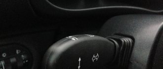
The steering column switch assembly consists of a connector secured with a clamp to the steering shaft bracket and two switches with levers. The left switch turns on the turn signals and switches the headlights, the right switch controls the windshield washer and wiper, as well as the trip computer in the instrument cluster.
The switches are secured in the connector with latches.
Rice. 10.8. Positions of the steering column switch levers
The positions of the switch levers are shown in Fig. 10.8, the contacts closed in this case are given in table. 10.7.
Table 10.7 Contacts closed at different positions of the steering column switches
* Non-fixed lever positions.
Contact numbers of the turn signal and headlight switch
Wiper and washer switch contact numbers
You will need a tester.
1. Disconnect the wire from the negative terminal of the battery.
4. Disconnect the connectors with wires from the left steering column switch...
5. ...from the trip computer control block...
6. ...and from the right steering column switch.
7. Squeeze the plastic clips of the left steering column switch on both sides...
8. ...and remove the switch from the connector.
9. Similarly, remove the right steering column switch.
10. To check the switches, connect a 12 V test lamp to the corresponding contacts indicated in the table. 10.7 (here is shown checking the inclusion of the left turn signal). Move the switch lever to the position corresponding to the contacts being tested - the lamp should light up. Otherwise the switch is faulty.
11. Install the steering column switches in the reverse order of removal.
Steering column switches on a Lada Priora car fail quite rarely, but after a mileage of 150 thousand km. or higher, one of them may fail. Most often, it is the left lever that breaks, which controls turning on the turn indicators and switching from high to low beam headlights. Yes, it’s clear here that you have to turn on the turns several dozen times a day, while using the windshield wiper or washer several times a month, or even less often.
Steering columns from Kalina, Priora and Chevy Niva
Note. On the VAZ 2110 you can easily and simply install switches from Lada Kalina, Chevrolet Niva or some foreign cars.
Features you need to know about
Replacing the steering column switch for a VAZ 2110
Let's look at some features of steering column switches from other cars that we want to install in the VAZ 2110:
- The main thing is the connector, which must match the VAZ 2110 and then there will be no problems.
- It is also recommended to pay special attention to the shape of the switch. For example, the steering column shifters from the Priora become further from the steering wheel than the tenth shift paddles. In this case, you have to lengthen the steering shaft or install another one from the same Kalina.
Steering column switches VAZ 2110
Note. There is another way: bend the steering column switch and cut off the excess part, and then glue it at a different angle, but this is not entirely correct. We need to think about safety, but a glued-on steering column does not fit in with this. Therefore, if we change the steering columns from Priora, Kalina or Niva, we will have to put up with a large distance of levers.
Conventional DIY installation of steering column stalks
- Disconnect the positive wire from the battery.
- Now remove the lower steering column casing by unscrewing the 7 fastening screws.
- Lower the steering column down.
- Remove the upper steering column casing.
VAZ 2110 replacement of steering column switches
- We find two plastic clips and squeeze them to remove the windshield wiper switch (see Replacing windshield wipers on a VAZ 2110 on your own) from the base.
- Disconnect the block with wires.
- We now remove the turn signal and headlight switch, again, squeezing the two plastic clips.
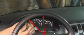
We take a test lamp at 12 and connect it to the corresponding contacts:
Replacing steering column switches VAZ 2110
- If the lever is in the first position, then everything is turned off.
- If the lever is in the second or third position, then the numbers of closed contacts will be 49a-49aL and this is a left turn indicator.
- If the lever is in the fourth or fifth positions, then this is a right turn indicator and the numbers of closed contacts: 49a-49aR.
- If the lever is in the sixth position, then these are low beam headlights and the numbers of closed contacts: 56-56b.
- If in position seven, then this is a high beam alarm and the numbers of closed contacts are 30-56a.
- High beam is position eight and the contact numbers here are 56-56a.
Steering column switch VAZ 2110, VAZ 2111, VAZ 2112
Instructions for repairing electrical equipment of Lada 2110, checking and troubleshooting vehicle devices. Replacement of parts for VAZ 2111, VAZ 2112, VAZ 2110. Steering column switch Description of devices and equipment of the VAZ 2110, VAZ 2111, VAZ 2112 electrical equipment repair diagrams, testing and adjustment
It consists of a connector secured with a clamp to the VAZ 2110 steering gear shaft bracket and two switches. The left switch controls the turn signals and headlights, while the right switch controls the washer and windshield wipers. On the connector of the VAZ 2111 steering column switch there are spring-loaded contacts for the sound signal.
Closed contacts of the steering column switch
1 – lever for switching direction indicators and headlights. If, with the ignition on, the lever is in position: I – the direction indicators are off; the low beam of the headlights is on if the headlights are energized by the external lighting switch; II – left turn indicators are on (not fixed position) III – left turn indicators are on (fixed position) IV – right turn indicators are on (not fixed position) V – right turn indicators are on (fixed position) VI – (self) high beam is on headlights on, regardless of the position of the external lighting switch VAZ 2112 (not fixed position) VII – (pull) the high beam headlights are turned on if the external lighting switch energizes the headlights (fixed position)
2 – switch lever for windshield wipers and washers. If the lever is in position: I – the windshield wiper is off II – the intermittent operating mode of the windshield wiper on the VAZ 2110 is switched on (not fixed position) III – the intermittent operating mode of the windshield wiper is switched on (fixed position) IV – the first speed of the windshield wiper is switched on V – the second speed of the windshield wiper is turned on VI – (towards itself, regardless of the position of the lever) the windshield washer is turned on (not a fixed position) VII* – the rear window wiper is turned on (fixed position) VIII* – the rear window washer is additionally turned on (not a fixed position )
Ignition switch VAZ 2110, VAZ 2111, VAZ 2112
Steering column switch VAZ 2110, VAZ 2111, VAZ 2112
Removal and installation of the steering column switch VAZ 2110, VAZ 2111, VAZ 2112
Sound signal VAZ 2110, VAZ 2111, VAZ 2112
Replacing the sound signal of a VAZ 2110, VAZ 2111, VAZ 2112 car
Windshield washer and cleaner for VAZ 2110, VAZ 2111, VAZ 2112
Assembly and installation of glass cleaner VAZ 2110, VAZ 2111, VAZ 2112
Removal and installation of the electric motor and windshield washer reservoir VAZ 2110, VAZ 2111, VAZ 2112
Trip computer VAZ 2110, VAZ 2111, VAZ 2112
Removal and installation of instrument cluster VAZ 2110, VAZ 2111, VAZ 2112
Removing and installing the on-board system unit
Replacing the clock and display unit of the on-board control system of VAZ 2110, VAZ 2111, VAZ 2112
Units and electrical circuits of VAZ 2110, VAZ 2111, VAZ 2112
Diagnostics of electrical equipment of the Lada 2110 car. Instructions for troubleshooting the lighting system. Repair of the generator and starter of the Lada 2111. Diagram of the Lada 2112 car.
Modification of the steering columns on the VAZ 2110
If the driver is not interested in the replacement process itself, but only needs to eliminate the clicking of the steering column switches, then we can advise simply carrying out modifications.
Eliminating clicks
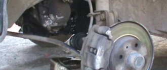
- We remove the switches from the VAZ 2110. Usually, no difficulties arise in this process.
- We disassemble the steering columns by snapping off the top cover with a screwdriver (small size).
- We find a small slide inside the switch (it is this that is responsible for the loud switching).
- Now you need to find a suitable rubber, for example, a car door seal (old and no longer needed). This very piece of rubber will need to be glued to the points of contact between the scenes.
Advice. To make the switching happen more smoothly, it is recommended to slightly file the plastic bump. We try to make the tip more rounded, otherwise it will jump. If this cannot be done, then you can use another method: weaken the spring.
- Let's put everything back together.
- We cover the switch body with some kind of vibration material. It is recommended to do the same with the steering shaft casing.
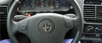
Closing the openings of the steering column switches
Openings can be closed easily and simply
Sitting behind the wheel of a VAZ 2110, you cannot help but notice the large gaps located near the steering column switches. This looks very unaesthetic and not at all practical. Let's try to close them:
- Take a piece of black carpet.
- We cover the steering column switch with Moment glue.
- We wait until the required time dries.
- We glue the carpet directly onto the steering column switch, closing the gap.
Note. It is not necessary to use only carpet. If you don’t have it, then you can take a piece of modelin or even an old felt boot.
You can easily replace the switch yourself, following the instructions. Thus, it will be possible to save the price of services in specialized workshops. During the work process, it is recommended to study photo and video materials.
Topic: Kalina steering wheel in VAZ 2110
I read an article on installing a Kalina steering wheel in a VAZ 2110, and some questions arose. Is there a special Kalinovsky steering wheel for tens or can you just remove the steering wheel from Kalina and put it on 2110?
Added: 2012-08-27 11:49:54
The thing is that I went to the market and was told that a steering wheel for Kalina costs 1,500 rubles. and a special one for 2110 - 2200 rubles. And what's the difference? Or this steering column cover costs 700 rubles.
Fuse box in the passenger compartment of VAZ-2170, -2171, -2172
The fuse box in Priora is located at the bottom of the dashboard, on the left side of the steering wheel. To get to it, you need to open the cover, which is held on by three latches. Rotate each locking knob 90 degrees and pull the lid down and it will snap open.
Fuses in the interior mounting block
F1 (25 A) - radiator cooling fan. If your fan does not work, check its motor by applying 12 V directly to it from the battery. If the engine is working properly, then most likely the problem is in the wiring or connectors. Check the serviceability of relay K1.
The fan in the Priora usually turns on at a temperature of 105-110 degrees. Do not allow the engine to overheat, watch the arrow of the temperature sensor.
If the fan runs constantly and does not turn off, check the coolant temperature sensor located on the thermostat. If you remove the connector from the working sensor, the fan should turn on. Check the wiring to this temperature sensor, as well as the contacts of relay K1, move this relay, clean the contacts. If this is the case, replace it with a new relay.
F3 (10 A) - high beam, right headlight. F4 (10 A) - high beam, left headlight. If the headlights do not shine on high beam, check the K7 relay and the headlight bulbs. The steering column switch, wiring or connectors may also be faulty.
F5 (10 A) - sound signal.
If the signal does not work when you press the steering wheel button, check relay K8. The signal itself is located under the radiator grille; you can get to it by removing the plastic casing from above. Check it by connecting the voltage to 12 V. If it doesn’t work, try turning the adjusting screw, or replace it with a new one.
F6 (7.5 A) - low beam, left headlight. F7 (7.5 A) - low beam, right headlight. When replacing lamps, be careful; there are separate lamps for the low and high beams, so they can be easily confused. It is better not to install lamps in high-power headlights; the reflectors may melt and the desired effect will not be achieved. Most low beam headlight problems that cannot be corrected by conventional means can be related to the light control module (LCM). The low beam relay is only available in cars equipped with a light sensor, it is located in the place of relay K1; on most cars this relay is not in the mounting block; the low beam circuit goes through the MUS block. It happens that the tracks in the block burn out; if there are problems, it is better to replace it with a new one. If the windshield wipers turn on spontaneously when the low beam is not working correctly, the problem is most likely in the windshield wiper control unit, located in the center of the dashboard, the topmost block, next to the radio, is best reached from the glove compartment, or by hand through the removed console covers at the feet.
F8 (10 A) - alarm signal. If the alarm does not work, also check relay K9.
F9 (25 A) - stove fan.
If your stove does not work in any mode, the problem may be with the stove speed controller or with the engine. Check the stove motor by applying 12 V voltage directly to it. If it does not work, remove it, open the cover and check the condition of the brushes. If the stove does not work only in the first modes, but works in the last mode, most likely you need to replace the heater resistance, located under the hood on the fan scroll.
The price of these resistors is about 200 rubles. Also check that the filter and all pipes are clean and that air flows normally into the stove. If the stove fan squeaks or turns with difficulty, try lubricating it. If the stove turns on and off, check the connectors and contacts in them, they could have melted or oxidized, in this case, replace the connector.
If the car has an air conditioner, the thermal fuse may burn out; it is located near the additional resistance; the fan fuse in the configuration with the air conditioner is located under the hood in the power fuse box.
F10 (7.5 A) - instrument panel, interior lights, brake lights.
If your instrument needles and gauges on the panel stop working, most likely the problem is in the connector that fits it. Check to see if it has fallen out and inspect its contacts. It may also be due to burnout of the tracks on the panel board. In this case, you need to disassemble the panel and inspect it. It can be easily disassembled by unscrewing the screws on top under the trim, on the bottom near the fuse cover and on the side.
Modification of the steering columns on the VAZ 2110
If the driver is not interested in the replacement process itself, but only needs to eliminate the clicking of the steering column switches, then we can advise simply carrying out modifications.
Eliminating clicks
- We remove the switches from the VAZ 2110. Usually, no difficulties arise in this process.
- We disassemble the steering columns by snapping off the top cover with a screwdriver (small size).
- We find a small slide inside the switch (it is this that is responsible for the loud switching).
- Now you need to find a suitable rubber, for example, a car door seal (old and no longer needed). This very piece of rubber will need to be glued to the points of contact between the scenes.
Advice. To make the switching happen more smoothly, it is recommended to slightly file the plastic bump. We try to make the tip more rounded, otherwise it will jump. If this cannot be done, then you can use another method: weaken the spring.
- Let's put everything back together.
- We cover the switch body with some kind of vibration material. It is recommended to do the same with the steering shaft casing.
Closing the openings of the steering column switches
Openings can be closed easily and simply
Sitting behind the wheel of a VAZ 2110, you cannot help but notice the large gaps located near the steering column switches. This looks very unaesthetic and not at all practical. Let's try to close them:
- Take a piece of black carpet.
- We cover the steering column switch with Moment glue.
- We wait until the required time dries.
- We glue the carpet directly onto the steering column switch, closing the gap.
Note. It is not necessary to use only carpet. If you don’t have it, then you can take a piece of modelin or even an old felt boot.
You can easily replace the switch yourself, following the instructions. Thus, it will be possible to save the price of services in specialized workshops. During the work process, it is recommended to study photo and video materials.