Lighting control unit:
1 — switch for external lighting and instrument lighting; 2 — brightness control for instrument lighting; 3 — headlight electric corrector regulator; 4 — switch for rear fog lights; 5 - plug (on some cars the fog light switch)
Switch block on the driver's door: 1 - left front door power window switch; 2 — central locking switch; 3 - right front door power window switch
Source
Hazard Alarm Button Pinout
One of the main devices in the flashing type hazard warning light system installed on cars and other motor vehicles is the hazard warning switch.
Hazard switches VK422, 24.3710, 245.3710, 37.3710, 375.3710, diagrams, replacing VK422 with 24.3710 in case of malfunctions.
If the turn signal lamps do not work when the hazard lights are turned on, the reason for this may be a malfunction of the turn signal switch, hazard warning switch, turn signal relay, a blown fuse or filaments of the turn signal lamps, a break or short circuit of the wires.
In the case when, when the direction indicators are operating, the side lights or brake lights begin to blink, or in general the light signaling devices begin to behave inexplicably, then this is usually due to poor contact with ground. Therefore, in such cases, first of all, you need to check the fastening of the ground wires in the trunk, near the rear lights and near the headlights and sidelights.
If the hazard warning switch is faulty or out of order, and it could not be repaired, and there is no opportunity to purchase a similar one, then you can replace it with a switch of a different brand.
The internal switching and marking of the terminals is different for different types of emergency switches; this must be taken into account when connecting the wires. For proper installation, it is also important what type of turn signal relay-breaker is used in the hazard warning and turn signal circuit. General information about connecting wires to switches VK422 and 24.3710 for different system configurations is given in the table below.
Connecting the terminals of emergency light switches VK422, 24.3710, 245.3710 in combination with relay breakers RS950 and 23.3747.
When using the table, you need to keep the following in mind. The connection of terminals “4” and “5” for the VK422 switch or “1” and “3” for 24.3710 can be swapped. In the event that cars have a relay for dual-mode operation of signal lights, then when replacing VK422 with switch 24.3710, it is not possible to maintain its functionality. Therefore, if such a replacement is necessary, the dual-mode light alarm will have to be abandoned and the relay will have to be deactivated.
Appearance, switching diagram and contacts of the emergency light switch 6HD 002 535 Hella.
The 6HD 002 535 Hella switch is unique in that it essentially has an electrothermal turn relay built into it. This allows you to ensure the operation of the emergency lights when the standard turn relay fails.
We present to your attention a diagram for switching on the direction indicators and hazard warning lights for the VAZ-2106 : 1 - sidelights;
2 — side direction indicators;
3 - battery;
5 — ignition switch;
6 — main fuse block;
7 - additional fuse block;
8 — relay-interrupter for alarm and direction indicators;
9 - indicator lamp for direction indicators in the speedometer;
10 — alarm switch;
11 — rear lights;
12 - direction indicator switch in a three-lever switch
We present to your attention a diagram of turn signals and emergency lights on the VAZ-2109 and similar modifications.
1 — Headlight 2 — Turn signal repeaters 3 — Fuse mounting block 4 — Ignition relay 5 — Ignition switch 6 — Indicator lamps on the instrument cluster 7 — Tail lights 8 — Hazard warning switch 9 — Turn signal switch K2 — Turn signal and relay alarm
DIY repairs: common problems
So, you don’t need to have a mechanic’s education to do some simple work with your own hands.
It is important to follow safety regulations. Always (in the case of a new car) when purchasing a Lada Kalina, it comes with detailed instructions that help you understand the intricacies of the process
The following features of doing it yourself can be highlighted:
- It must be remembered that the Lada Kalina is available with two types of engines and standardized units, so when starting repairs, you need to be 100% sure of the modification.
- If repairs are carried out related to the fuel system or engine, it is necessary to extract the treated gases.
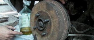
- Oil and other liquids are added only according to the standards specified in the instructions, otherwise the filter will need to be replaced.
If you are going to paint the body, remember that it is better to do it in a ventilated area. You also need to have a paint sprayer; other equipment is not suitable here. Parts that will not be painted, such as headlights, need to be covered with paper.
Kalina hazard warning button pinout
On the Internet there are many posts about moving the emergency gang button on the second generation Samara, and not a single post about moving the button on Kalina. And in fact: the button is conveniently located, good-looking and does not have a single obvious disadvantage. But this is necessary. Why? The answer will be given later. And now the process itself. For transfer the following were purchased: — emergency signal button GAZ 757.3710 and a connector for it; — emergency warning button Kalina 379.3710-01M; — a 12V relay with four contact groups and a DIN rail connector for such a relay; - 3 meters of wire. The standard button and relay connector were modified with a hacksaw, wire cutters, file, soldering iron and hot glue. As a result we got this:
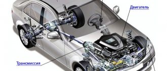
Some information about Lada Kalina
Lada Kalina has been produced by the Volzhsky Automobile Plant since the end of 2004; since 2013, Togliatti began producing the second generation of the polar car. Kalina-1 is presented in three bodies:
- sedan, model 1118;
- hatchback, 1119;
- station wagon (Combi), 1117.
Three types of gasoline engines are installed on Kalina-1:
- 1.4 l 16-valve 11194 with a capacity of 89 hp. With.;
- 1.6 l 8-valve 21114 (81 hp);
- 1.6 l 16-valve 21126 (98 hp).
The first generation car has only a manual transmission with five gears. The front suspension of the VAZ car is a typical MaCpherson; a beam with a stabilizer, shock absorbers and springs is installed on the rear axle.
Electrical diagram of the rear wiring harness Kalina 2
1, 2 – rear wiring harness blocks to the instrument panel wiring harness blocks; 3 – right side direction indicator; 4 – left side direction indicator; 5 – hand brake sensor; 6 – rear wiring harness block to the tailgate wiring harness contacts; 7 – interior lighting unit; 8 – switch in the driver’s seat belt; 9 – trunk lighting; 10 – electric fuel pump module; 11 – right lamp; 12 – rear wiring harness block to the tailgate wiring harness contacts; 13 – left lamp; 14 – rear wiring harness block to rear left door wiring harness block; 15 – rear wiring harness block to rear right door wiring harness block; 16 – rear wiring harness block to the front right door wiring harness block; 17 – rear wiring harness block to the front left door wiring harness block; 18 – airbag control unit; 19 – rear wiring harness block to the front wiring harness block; 20 – block of the rear wiring harness to the block of the wiring harness of the parking system sensors; 21 – control unit and alarm unit of the safe parking system; 22 – parking system switch; 23 – speaker of the safe parking system; 24 – switch for interior lighting in the driver's door pillar; 25 – interior light switch in the right front door pillar; 26 – switch for the interior lighting in the pillar of the right rear door; 27 – interior light switch in the left rear door pillar; 28 – right seat electric heater switch; 29 – left seat electric heater switch; 30 – electric heater of the right seat; 31 – electric heater of the left seat; 32 – driver’s seat belt pretensioner; 33 – passenger seat belt pretensioner; 34 – central unit of body electronics; 35 – sensor for automatic glass cleaning system (rain sensor); 36 – rain sensor sensitivity regulator; 37 – rear wiring harness block to the instrument panel wiring harness block; 38 – right rear speed sensor; 39 – left rear speed sensor.
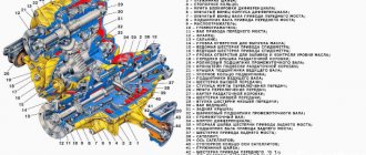
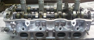
Device
Cars in the first generation were equipped with a five-speed manual transmission VAZ-2181, with five forward gears and one reverse gear. The mechanism is based on the well-known gearbox from the VAZ-2108 with minor upgrades. The gearbox is combined with the main gear and differential.
The Kalina gearbox is designed as standard. It consists of the main drive gear, secondary and input shafts, gear forks, reverse sensor, housing, gear shift mechanism and central lock.
Manufacturers thought for a long time about what and how to improve in the gearbox mechanism, as a result they decided not to interfere with the gear mechanism, otherwise huge costs would be required to launch the gearbox into series. Without the necessary equipment, it is impossible to obtain the proper quality of gear engagement and synchronizers.
The VAZ-1117 (“Kalina”) gearbox is the first for which AvtoVAZ specialists made a computer calculation of each part in the mechanism that is subject to loads. Crankcases, forks, levers and other elements were calculated and simulated using special software. Thus, the design was not only optimized, but also more reliable.
Materials:
1. Electrical tape (preferably blue, as it is especially durable) 2. Four-pin turn signal relay from VAZ 2106 3. Relay connector 4. Six-pin alarm switch off button 5. Connector for the button 6. Wire for mounting and connecting the above. Tools: 1. Pliers with wire cutters 2. Flat-head screwdrivers 3. Phillips screwdrivers 4. Open-end wrench 10 5. Knife For those who want to save money at the expense of manufacturability: you can use the original relay from the VAZ 2101, but in this case it will work adequately not guaranteed as this relay is very sensitive to load changes. For this reason, the following installation method involves replacing the relay with a more modern one. Let's get started, unscrew the nut securing the turn signal relay and disconnect three multi-colored wires from it. Next, we determine where to install the hazard warning button. Here we give freedom to our imagination, but a lot also depends on what kind of panel is installed in your car. To the second contact of the relay we connect the wire removed from the contact of the old relay, marked with the letter “L”, and connect all this to the seventh contact of the alarm button. We connect the first contact of the emergency light relay to the fourth contact of the button. We connect the third contact of the relay with the wire removed from the “P” contact of the old relay. We attach the wire coming from the fourth contact of the relay to the car body. The optimal solution would be to secure the wire under the fastening nut of our relay.
Scheme of emergency lights (hazard warning lights) for VAZ 2101 cars
Thanks for subscribing!
Now tighten the relay mounting nut with moderate force so as not to break the plastic mount. Then we connect the second contact of the button to the positive wire of the old relay. We connect the first and third contacts of the button to the steering column turn signal switches in any order. The eighth contact of the button is connected to a constant “plus” (independent of the position of the key in the ignition switch). It is advisable to protect this circuit with a fuse. The most suitable would be to install a fuse rated 8A. Next, you should wrap the wires with electrical tape and secure them so that they do not dangle, and install all the previously removed casings and panels. Now we have a full-fledged alarm system and can live a new, full life. The entire procedure for installing an alarm system on a VAZ 2101 takes 2-3 hours.
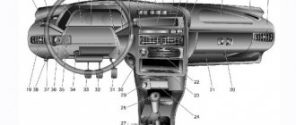
Instrument clusters and tuning
Tuning the Kalina torpedo
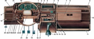
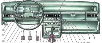
The listed devices and controls are located on the so-called dashboard of the car. You can install an original torpedo on Kalina, thereby diversifying the interior of the car.
The instrument cluster is closed with a special cover, which is an overlay on the panel. If necessary, the cover can be easily removed and replaced.
Auto-tuning instructions can be found on special websites and forums. Tuning the combination of all devices is not difficult if you have minimal skills in working with a soldering iron. The instrument cluster on Kalina is identical to the combinations on the VAZ 2118 and 2119. Nowadays, the GF 618 instrument cluster on Kalina, based on LEDs, is very popular; it has a built-in route diagnostic computer.
A panel that was installed at the factory can quickly become boring. In order not to purchase an alternative, but very expensive panel with a built-in computer, you can make inexpensive tuning with the existing one. The easiest way is to install an overlay on the instrument panel, which can be easily purchased using the services of online stores.
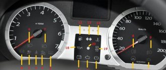
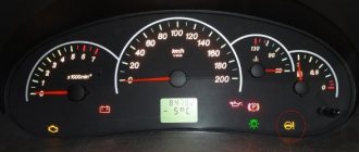
Using the instrument panel, the driver can monitor the vehicle’s condition, driving characteristics and other functions and processes that affect the safety of movement. Also, with the help of indicators, the car owner will be able to operate it correctly. Next, a description of the indicators on the instrument panel will be given to make it easier for a novice driver to understand.
Windscreen wipers
As for the windshield wipers of the Lada Priora, the electrical circuit in this case has a special programmable control unit. The circuit contains fuses to protect against overvoltages and short circuits.
The windshield wipers are turned on with a switch located near the steering wheel. The switch has eight positions, four of which are used to control the purifier. One position on the switch turns on the glass washer, the other two positions control the rear wiper. Another position is responsible for the disabled state of the windshield wiper.
Gearbox lever rattling
For LADA Kalina, a typical malfunction is rattling in the area of the gearshift lever, which mainly becomes noticeable when the engine is running at speeds of about 3000. The source of the side sound is the bushing, which is made a little thicker than necessary, and because of this, a gap appears in the mount. To resolve this problem you need to do the following:
- remove the handle cover, which is attached with latches;
- using two 13mm wrenches, unscrew the nut and bolt;
- remove washers and bushings;
- to eliminate rattling, the bushing in the middle needs to be slightly sharpened in width or the mount should be lubricated with sealant;
- Having done this, mount everything back. The sealant does not help out every time, but if you sharpen the bushing by 0.3 mm, the result is guaranteed.
It’s safe to say that repairing a Lada Kalina car yourself is not so scary. Every car enthusiast has the opportunity to eliminate minor malfunctions of this car. You just need to believe in yourself, follow our advice and everything will work out!
Ignition system diagram Lada Kalina Lux
1 — oil pressure warning lamp sensor;
2 — coolant temperature indicator sensor; 3 — additional fuse block; 4 — fuses for the electric fan of the engine cooling system; 5 — electric fuel pump relay; 6 — relay for the electric fan of the engine cooling system; 7 - ignition relay; 8 — relay 2 of the electric fan of the engine cooling system; 9 — relay 3 of the electric fan of the engine cooling system; 10 — electric fan of the engine cooling system; 11 — throttle position sensor; 12 — idle speed regulator; 13 — coolant temperature sensor; 14 — diagnostic block; 15 — ignition system harness block to the instrument panel harness block; 16 — solenoid valve for purge of the adsorber; 17 — speed sensor; 18 — ignition system harness block to instrument panel harness block 2; 19 — mass air flow sensor; 20 — crankshaft position sensor; 21 — oxygen sensor; 22 - controller; 23 — rough road sensor; 24 — diagnostic oxygen sensor; 25 — ignition coil harness block to the ignition system harness block; 26 — ignition coils: 27 — ignition system harness block to the ignition coil harness block; 28 — spark plugs; 29 — nozzles; 30 - resistor; 31 — air conditioning system pressure sensor; 32 — blocks of the ignition system harness and injector wiring harness; 33 - phase sensor; 34 - knock sensor. Ignition system wiring harness -11184-3724026-10. Ignition coil wiring harness -1118-3724148-00. Injector wiring harness -11184-3724036. A - to the “plus” terminal of the battery.
Typical diseases of Lada Kalina-1
Major breakdowns with the car do not happen often, but there are plenty of various unpleasant little things. The clutch on a VAZ car is not highly reliable and has a long service life, regardless of the engine type, and it can fail after 40-50 thousand kilometers. The main cause of failure is a collapsed clutch disc.
It is necessary to constantly monitor the oil level in the engine - it can leak through the gaskets and escape through the piston rings. On the instrument cluster there is only an oil pressure warning lamp; there is no dial indicator. When the indicator lights up constantly, it may be too late - the crankshaft will knock.
A well-known disease of all VAZ gearboxes is increased noise. It is difficult to get rid of gearbox noise; in some cases, even replacing bearings or filling with high-quality transmission oil does not help. Gearboxes also whine on new cars, so AvtoVAZ has modified the transmission more than once.
Also, starting with the “eights” and “nines”, the thermostat in the engine was considered a problematic part, and the valve in it could get stuck in any position. It's unpleasant if the engine doesn't warm up to the required operating temperature, but when the engine overheats, it's even worse.
Three main problems most often arise in the electrical system of the Lada Kalina-1:
- the bearings and diode bridge in the generator quickly “die”;
- The ignition module often fails;
- The driver's door power window cable breaks.
If the ignition coil is punctured, either the first and fourth or the second and third cylinders stop working in the engine. The ESP cable breaks due to the fact that it jumps off its guides.
The reason for the crunching of outer CV joints is a lack of lubrication; thrifty factory workers do not provide enough of it. As a result, intensive wear of the hinges occurs, and the “grenade” has to be replaced.
A broken timing belt is always unpleasant, but if on an 8-valve 21114 you can change the belt drive and move on, then on engines 11194 and 21126 the valves bend from the oncoming impact with the pistons, and repairs are quite expensive. A break can also occur due to a jammed water pump, so if the pump becomes noisy, it needs to be replaced urgently.
What does the hazard warning button hide?
The design of the first light alarms was quite primitive; they consisted of a steering column switch, a thermal bimetallic breaker and light direction indicators. In modern times, things are a little different. Now the alarm system consists of special mounting blocks, which contain all the main relays and fuses.
True, this has its drawbacks, for example, in the event of a break or combustion of a section of the circuit that is located directly in the block, to repair it it is necessary to disassemble the entire block, and sometimes it may even require its replacement.
An emergency alarm shutdown button with outputs for reconnecting lighting circuits (in case of a change in operating mode) has also appeared. Of course, we cannot fail to mention the main components thanks to which the driver can notify other road users about an ongoing unusual situation - lighting devices. They include absolutely all the direction indicators that are on the car, and two additional repeaters, the latter being, as already mentioned, on the surface of the front wings.
On the electrical circuit of the Lada Kalina model, the pinout of connectors is carried out in several stages. According to the factory drawings, the general position of the elements is initially revealed, then each node is deciphered separately.
- Right front headlight assembly.
- Sensor indicating the position of the hood lock.
- Powering the horn.
- Starter terminal block.
- Battery power cables.
- Generator working unit.
- Voltage supply terminal for the wiper drive.
- Left head optics contact block.
- Right door lift chip.
- Likewise for the glass lift gearbox.
- Output to driver's door speaker.
- Driver's door lock drive.
- Windshield washer reservoir motor.
- Overboard temperature meter sensor output.
- Standard ECM connection connector.
- Same as 12 for the front passenger.
- Indicator of the remaining brake fluid in the expansion tank of the system.
- Same as 11 for the front passenger.
- The front passenger door power window switch, located in the driver's control unit.
- Driver's door window lift key.
- Lock button.
- Power supply for the lift gearbox for the front passenger door.
- Input of the mounting assembly.
- Anti-theft control unit.
- Likewise for signaling.
- Pinout on the dashboard.
- Right turn.
- Glove compartment lighting.
- Glove box light switch.
- Stop key switch.
- Anti-theft ignition switch terminal.
- Headlight design.
- Supply current to the steering column lever connector.
- Left turn signal.
- Right rear speaker block.
- Rear right door electric lock drive.
- Window window heating unit.
- Reverse blocking.
- Hazard breaker.
- Adjusting the stove fan.
- Auxiliary resistor for the stove.
- Stove motor.
- Power supply for rear left speaker.
- Rear left door lock terminal.
- Power supply for fuel pump and float.
- White reverse lamp switch.
- Stop button.
- Cigarette lighter power supply.
- ZX blocking – solenoid power supply.
- Chips for a tape recorder or speaker system.
- Illumination of used ventilation and stove.
- Supplying voltage and signals to the EUR.
- Interior lighting lamps.
- Rear right lampshade.
- Power to the trunk lid lock.
- Cargo compartment lighting drive.
- State license plate illumination.
- Auxiliary stop lamp.
- Directly heated windshield.
- Cargo compartment illumination lamp.
- Left stern light.
Why did it happen so?
Perhaps the automatic requests do not belong to you, but to another user accessing the network from the same IP address as you. You need to enter the characters into the form once, after which we will remember you and be able to distinguish you from other users exiting from this IP. In this case, the page with the captcha will not bother you for quite a long time.
You may have add-ons installed in your browser that can make automatic search requests. In this case, we recommend that you disable them.
It is also possible that your computer is infected with a virus program that is using it to collect information. Maybe you should check your system for viruses.
If you have any problems or would like our support team, please use the feedback form.
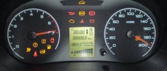
The instrument panel serves to inform the driver about all important processes occurring in his car. It is by using the scales, indicators, symbols and lamps located on this device that the person sitting behind the wheel is able to monitor the performance of components and systems. For the shield to function correctly as a single system, it requires regular diagnostics. It consists not only of scanning by connecting electronic reading devices to the computer, but also by visually monitoring the performance of all specified components of the dashboard (lamps, etc.).
So that the owner of the Lada Kalina, namely the instrument panel of this model we will talk about today, can easily navigate this complex device, the manufacturer kindly agreed to complete the car with the appropriate instructions. It is enough to familiarize yourself with its postulates and all the secrets of the dashboard will be revealed to you, then the instrument panel will not seem like something incredibly complicated.
The manufacturer did his best when developing the design of such a thing as the instrument panel on the Lada Kalina car. It is unlikely that you will be able to find owners dissatisfied with the “interface” of the device. The dashboard is painfully informative and primitive in terms of perceiving symbols and managing some of them.
Now let's move on to a more detailed consideration of the structural components of such an important element of the car as the dashboard. Many car owners will find a full description of the icons useful.
Replacing a dead battery
Let's say the LED located on the key fob body flashes quickly when you press any key. There will be no reactions from the central locker in this case. All of the above suggests that it is time to replace the battery. Details are discussed below.
If the LED flashes when you press the key, you can still start the car with that key. The immobilizer can easily read the code written into the key fob chip, and synchronization will not be lost either. But it is recommended to hurry up when replacing the battery.
So, to disassemble the key fob body, you will need a Phillips screwdriver. Having unscrewed one self-tapping screw, use a knife to separate the halves that make up the housing structure. The result looks like this:
Once the circuit board is removed, look at which battery is being used. The first characters of the designation are the letters “CR”. Then comes a set of numbers.
When making a replacement, try not to leave the contacts free for more than 6 seconds. Otherwise, there is a high probability of loss of synchronization.
It can be summarized that the replacement operation is performed in three steps:
- We disassemble the case, determine the type of battery;
- We purchase the same battery;
- We are making a replacement.
Care must be maintained at every step.
Switching the central locking system to single unlocking pulse mode
The controller unlocks the doors in two steps: a single press on the “Open” button unlocks the driver’s door, and you can completely unlock the door with a second press. But according to AvtoVAZ instructions, it is possible to reconfigure the system, and then disabling the lock will be done in one step. The setup procedure looks elementary:
- The ignition is turned on with a key equipped with control keys;
- Press the “Open” and “Close” buttons on the key and hold them for 5 seconds;
- The buzzer should sound and then the keys will be released.
If a single signal sounds, it means that the system has entered the required mode. The question remains how to return it to its previous mode of operation. Perform the sequence discussed here a second time. At the end, a double signal will sound, which will confirm the transition to the previous settings.
The single pulse mode is characterized by the following. If the driver's door is opened with a key rather than using a key fob, the controller unlocks each door. However, the effect of pressing the “Open” button will look the same.
Features of the switching mechanism
If we recall the design and principle of operation of VAZ gearboxes for the Samara series, then the shift mechanism in them was from below and immersed in an oil bath. After parking in the cold, the oil in the gearbox thickened and the gears shifted very, very slowly until the engine and gearbox warmed up. At the bottom of the gearbox, clamps for the fork and reverse gear rod, a reverse sensor, and a gear selection seal were installed - each element was a potential source of oil leakage. Sealants helped with this, but they did not radically solve the problem. And at AvtoVAZ they decided to move the mechanism up.
The new switching mechanism in the VAZ-1119 (“Kalina”) is a special separate unit. It can be installed and removed without the need to disassemble the gearbox. This is an excellent solution and is useful not only for fast and cheap production, which is also appreciated by repairmen. Now repairing the switching mechanism has become much easier. Thanks to the use of a selector grid, all gears are switched on much more accurately. The mechanism also has a lock against engaging reverse gear - reverse gear is only available from neutral.
The icing on the cake, or rather in the box, is the special selector plate. It was she who influenced the accuracy of gear shifting. The plate replaced the previously standard locking and return springs. To develop the plate, it took a long time to analyze the work of a person with a gearbox selector. The force on the lever was calculated using a special software package.
Pulse programming
When connecting a central lock, it is not enough to perform all the steps in the correct sequence; you also need to select the required pulse duration for the locks to operate. If it is too large, the actuators will overheat; if it is insufficient, it will not be enough to open and close. In the luxury configuration, all electronics usually “fall asleep” after 15 minutes of inactivity. To awaken it, an additional impulse is needed.
Central locking is a simple device, but it can secure your car from criminals much more effectively than a police cap on the passenger seat. The centralized door lock system is the most convenient way to quickly open and close them. If this security system is supplemented with a good car alarm, this will prevent you from ending up in a situation where your car is stolen or damaged.
Having tried to open the car using the key fob, one fine day you may find that the lock continues to operate and the car does not respond to key presses. In such a situation, it will be possible to unlock one door or even the central locking system by simply unlocking the driver's door lock. Only the security mode is not deactivated. The central locking, in turn, may not respond to commands for two reasons - the battery in the key fob is dead or synchronization is lost. How to solve these problems is discussed further.