VAZ-2115 dashboard diagram
The controls of the VAZ-2115 passenger car are located in accordance with the UNECE norms and regulations. For greater ease of use of handles, buttons, switches and control devices located on the dashboard, they have graphic symbols indicating their functional purpose.
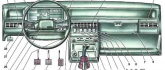
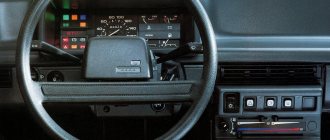
Rice. 1.1 Instrument panel of the VAZ-2115 (diagram).
The dashboard diagram (Fig. 1.1) includes controls:
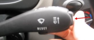
1 – lever-switch for headlight or turn signal modes.
2 – nozzle for blowing the front door glass.
3 – instrument cluster.
4 – steering wheel.
5 – button to turn off sound signals.
6 – button to turn off the alarm. Pressing the button causes the warning light and direction indicators to flash.
Photo 1. Hazard switch off button
7 – ignition switch combined with an anti-theft device. Never turn off the ignition or remove the key from the lock while driving, otherwise the steering will be blocked and the vehicle will lose control. The ignition key can have three positions:
- 0 – “disabled”. Consumers are disconnected, the key can be easily removed. When the key is removed, the closing mechanism of the anti-theft system is activated. To guarantee the steering shaft block, turn the steering wheel left or right until it clicks. To turn off the anti-theft device, you need to insert the key into the ignition and, turning the steering wheel left and right, turn the key to position “I”;
- I – “ignition”. The ignition is on, the key is not removed, the steering is unlocked;
- II – “starter”. The key cannot be removed, the steering is unlocked. The position is achieved by turning the key to overcome the elastic force of the spring. The key is not locked in this position; it must be held by hand for the starter to operate. The ignition switch is also equipped with a starter activation unit while the engine is running.
To repeat turning on the starter after a failed start attempt, you need to move the ignition key from position “I” to position “0”, and then again to position “II”.
8 – switch lever for windshield washer and windshield wipers.
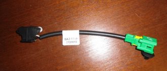
9 – immobilizer sensor, transmits a special code from the code key through the immobilizer to the engine control unit.
10 – set of signal lights for the on-board control system. The complex contains (Fig. 1.2): 1 – oil level drop signal; 2 – low level signal in the windshield washer tank; 3 – low coolant level signal; 4 – door open signal; 5 – signal of malfunction of the brake light and side lights; 6 – signal of wear of the linings on the brake pads; 7 – the signal indicates that the seat belts are not fastened.
11 – external lighting switch.
12 – block of keys for turning off fog lights, fog lights, heated rear window.
13 – trip computer, installed on some vehicles, designed to display one of the parameters: current fuel consumption (or average total fuel consumption), average speed, distance traveled, current time, time on the road.
14 – plug.
15 – control lamp for anti-lock braking system (ABS). Installed in place of the plug, if equipped with an anti-lock braking system.
16 – airbag control lamp. If the pillow itself is present, it is installed in place of the plug.
17 – central nozzles of the ventilation and heating systems of the cabin.
18 – cover of the glove box (upper). To use the upper glove compartment while the lower glove compartment lid is open, press the upper lid lock lever. The lock lever is located in the niche of the lower glove compartment on top.
19 – side nozzle of the ventilation and heating systems of the cabin.
20 – glove box cover (lower). To open it, you need to press the lock handle to the handle. If the external lighting is turned on, a special illumination of the inside of the box will automatically work.
21 – magazine shelf.
22 – control panel for interior ventilation and heating systems.
23 – socket for audio equipment. It is planned to install audio equipment that meets international standards in size and mounting principle.
24 – ashtray.
Watch a video of testing the dashboard of a VAZ-2115 passenger car here:
How to remove the dashboard of a VAZ-2115
If you decide to remove the instrument panel and carry out independent tuning or DIY repairs, you will need:
1. — Disconnect the ground wire from the battery.
2. — Remove the fastening screws to remove the steering shaft casing.
3. — After disconnecting the wires, remove the ignition switch.
4. — Remove the handles from the heater control levers
5. — Remove the headlight hydraulic adjustment handle.
Rice. 2.1 Instrument panel and its elements: 1 – instrument panel; 2 – dashboard trim; 3 – bracket; 4 – plug; 5 – ashtray; 6 – right cross member; 7 – right console screen; 8 – instrument panel; 9 – central bracket; 10 – left console screen; 11 – left cross member.
6. Remove the screws and disconnect the right 7 and left 10 screens from the instrument panel panel 8 (see Fig. 2.1).
7. Unscrew the screws securing the instrument cluster.
8. Unscrew the screws connecting the right cross member 6 to the dashboard panel 8.
9. Remove plug 4 and unscrew the screw securing the instrument panel panel 8.
10. Remove the instrument panel 8 as an assembly with switches for instrument lighting, fog lights, rear window heating, hazard warning lights and the cigarette lighter.
11. Disconnect all electrical wires.
12. To remove panel 1 assembled with trim 2, remove the screws securing the instrument panel to bracket 3 and left cross member 11.
13. If necessary, you can remove the screws and remove the dashboard trim, as well as the interior ventilation nozzles and air ducts.
Installation of the dashboard is carried out in the reverse order.
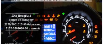
Designation of icons on the dashboard of the VAZ 2115
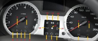
The following describes the warning lights and panel indications, which are indicated and numbered in the photo above.
| Number in order | Decoding |
| 3/4 | Turn signal indicators. They light up at the same time when the alarm is activated. |
| 7 | Minimum fuel level light. Lights up when the gas tank is empty. |
| 8 | Indicator for turning on external lighting. |
| 9 | The brake system is faulty. The brake fluid level and pad wear should be checked. |
| 10 | The high beam headlights are activated. |
| 12/15 | Information displays, basic information about the daily time and mileage is displayed here. |
| 13 | Emergency light activation key. |
| 14 | Check engine light. If it lights up, further movement is not recommended. |
| 16 | The battery is low. The operation of the generator should be checked. |
| 17 | The indication indicates that the handbrake lever is raised. |
| 18 | The warning light means that the engine oil pressure has dropped below normal. |
| 19 | This indicator is used exclusively on carburetor cars. The light indicates that the throttle valve is in the open position. |
Which bulbs are suitable for the 2114th model
In general, the current legislation provides for quite serious sanctions against motorists who dare to make any changes to the design of the vehicle at their own discretion. In accordance with the rules, they are obliged to replace components and assemblies only with analogues of those chosen by the manufacturer. Failure to comply with this requirement provides grounds for punishment of the driver.
Thus, more and more owners are installing LED lamps on their 2114 Ladas instead of the standard halogen ones. This choice is easy to justify. In particular, they:
- consume approximately 8-9 times less electricity, which means the load on the on-board power system is reduced;
- last 5-10 times longer;
- give brighter light;
- practically do not heat up.
Finally, the dashboard looks much more attractive, because the light bulbs can be of different colors - blue, red, green, etc.
The problem is that LEDs cost about twice as much, but this disadvantage is more than compensated by their longer lifespan. In addition, LED lamps are becoming cheaper every year.
Tidy 2115: description and purpose of buttons and knobs
If everything is simple with the levers on the steering rack, there is a headlight position switch and a turn signal switch on the left. Buttons are more difficult.
- Switch for outside parking lights.
- Activation of low beam headlights.
- Front fog lights.
- Rear PTFs. If not installed, reserve.
- Rear window heating button.
Lada 2115: the oil light on the center panel is on
If an icon in the shape of a watering can appears on the console, this indicates that there are problems in the engine lubrication system. This is caused by a drop in the oil level in the crankcase or a pump malfunction. If the engine is old, the problem may be caused by clogged oil lines.
What does the exclamation mark on the Lada 2115 tidy mean?
On the "tag" the symbol is used in only one form - a red indicator in a circle. The icon indicates a malfunction in the vehicle's brake system. If this symbol lights up while driving, stop and find the cause of the breakdown. Usually it is enough to add fluid to the expansion tank or replace worn pads.
The battery light on the dash is on 2115
A red battery icon indicates that the battery is not charging properly. A complete diagnosis of on-board systems associated with the generator set and its wiring is required.
VAZ 2115 controls and instruments
17 – central nozzles of the ventilation and heating system.
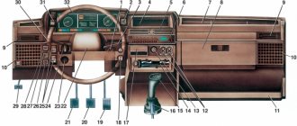
The location of the vehicle controls complies with UNECE standards and regulations. For ease of use, handles, buttons, switches and control devices located on the instrument panel are marked with functional symbols.
The following controls are located on the instrument panel (Fig. 1.7). 1 – lever for switching direction indicators and headlights. 2 – front door glass blower nozzle. 3 – instrument cluster. 4 – steering wheel. 5 – sound signal switch.
6 – alarm switch. Pressing the button turns on the flashing light of all direction indicators and the warning lamp in the instrument cluster. Pressing the button again turns off the alarm:
7 – ignition switch (lock) (Fig. 1.8), combined with an anti-theft device, is located on the right side of the steering column. The key in the lock can be in one of three positions:
0 – “off”. All consumers are turned off, the key is removed. When the key is removed, the locking mechanism of the anti-theft device is activated. To ensure that the steering shaft is locked, turn the steering wheel to the right or left until it clicks. To turn off the anti-theft device, you need to insert the key into the ignition switch and, turning the steering wheel slightly left and right, turn the key to position “I”; I – “ignition”. The ignition is on, the key is not removed, the steering is unlocked; II – “starter”. The key cannot be removed and the steering is unlocked. This is achieved by turning the key clockwise to overcome the spring force. In this position, the key is not fixed; for the starter to operate, it must be held by hand. The ignition switch is equipped with a starter lock when the engine is running. To re-engage the starter after an unsuccessful start attempt, move the key from position “I” to position “0”, and then again to position “II”.
8 – switch lever for windshield wipers and washer.
9 – the immobilizer warning sensor is installed on a vehicle with a fuel injection system, equipped with an electronic anti-theft system, and is designed to transmit a secret code from the working code key through the immobilizer unit to the engine control controller.
10 – block of signal lamps of the on-board control system. The following lamps are installed in the block (Fig. 1.9):
1 – warning lamp for an emergency drop in the oil level in the engine crankcase. Lights up orange if the oil level in the engine crankcase has dropped below the “MIN” mark of the indicator;
2 – warning light for insufficient liquid level in the windshield washer reservoir. Lights up orange if there is less than 1 liter of washer fluid left in the tank;
3 – warning light of insufficient coolant level in the expansion tank. Lights up orange when the coolant level on a cold engine drops below the permissible limit;
4 – warning light for open doors. Lights up red when the car door is not closed;
5 – warning lamp for malfunction of the brake light lamp or side lights. Lights up red if there is a malfunction of the brake light lamp when you press the brake pedal or any side light lamp when it is turned on;
6 – warning lamp for wear of the front brake pads. Lights up orange when you press the brake pedal and stays on until the ignition is turned off if the thickness of the front brake pads has decreased to 1.5 mm;
7 – warning light for unfastened seat belts. Lights up red if the driver's seat belts are not fastened.
11 – external lighting switch
. The switch block contains two mechanically connected switches: – side light switch 1. By successively pressing the switch key, the side lights in the headlights and rear lights are turned on and off; when the side lights are on, the control lamp with a green filter lights up in the button; – headlight switch 2. When you press the switch button (fixed position), the headlights turn on. When you press the button again, the headlights turn off.
12 – block of key switches includes the following
: – switch 1 of the front fog lights. The fog lights are turned on by pressing the switch button while the side light switch button is pressed, and at the same time the indicator lamp in the button lights up. When you press the button again, the fog lights turn off; – switch for 2 rear fog lights. When you press the switch button, the rear fog lights turn on if the exterior lighting is on. When you press the button again, the rear fog lights turn off; – switch 3 for heating the rear door glass. When you press the switch button, the glass heating is turned on, and at the same time the indicator lamp in the button lights up. When you press the button again, the heating turns off.
13 – trip computer
, installed on some of the cars produced, is designed to measure, accumulate and display on a digital display one of the following parameters: – current fuel consumption; – average total fuel consumption; – average speed; – distance traveled; – current time; – travel time.
15 – warning lamp for anti-lock braking system (ABS). Installed instead of a plug if the car is equipped with an anti-lock braking system.
16 – airbag status indicator lamp. Installed instead of a plug if the car is equipped with an airbag.
17 – central nozzles of the ventilation and heating system.
18 – cover of the upper glove box. To access the upper storage compartment with the lower storage compartment cover folded down, press the upper cover lock lever.
19 – side nozzle of the interior ventilation and heating system.
20 – cover of the lower glove box. To open it, press the lock handle against the handle. When the exterior lighting is turned on, a special flashlight illuminates the inside of the glove compartment.
21 – magazine shelf.
22 – control panel for the ventilation and heating system.
23 – socket for radio equipment. The installation of radio equipment is provided, corresponding in size and method of fastening to international standards.
24 – front ashtray.
25 – right front seat heating switch.
26 – left front seat heating switch.
27 – parking brake lever. To brake the car with the parking brake, lift lever 2 all the way up - the red warning lamp in the instrument cluster will light up. To release the brakes of the car, pull the lever up a little, press button 1 at the end of the lever handle and lower it all the way down - the warning light should go out.
28 – gear shift lever.
29 – cigarette lighter. To use the cigarette lighter, press the socket until it locks and release. After approximately 20 seconds, the cartridge automatically returns to its original position, ready for use.
30 – heater electric fan switch.
31 – accelerator pedal.
32 – brake pedal.
33 – clutch pedal.
34 – handle for adjusting the steering column angle.
35 – instrument panel lighting switch. Rotate the handle to adjust the brightness of the instrument lighting and switch backlights if the outdoor lighting is turned on.
36 – control knob for hydraulic headlight adjustment. Rotate the knob to adjust the angle of the headlight beam so as to prevent dazzling oncoming drivers. The hydraulic corrector handle positions correspond to the following vehicle loading options:
0 – one driver; 1 – all seats are occupied; 2 – all seats are occupied and cargo is in the luggage compartment; 3 – one driver and cargo in the luggage compartment.
This indicator is intended to help the driver choose the most economical engine operating mode. The econometer scale is divided into two zones - white and yellow. The white zone corresponds to the economical mode, the yellow zone to the high fuel consumption mode. Turn signal indicators When the direction indicators are turned on, this indicator starts flashing on the instrument panel. If the indicator flashes too quickly, this indicates that the direction indicator lamps may be burnt out. It is necessary to replace the burnt out lamp with a new one. Side light indicator This indicator lights up when the vehicle's exterior lighting is turned on. High beam headlight indicator This indicator lights up blue when the high beam headlights are turned on. "STOP" warning signal
This indicator is intended to help the driver choose the most economical engine operating mode. The econometer scale is divided into two zones - white and yellow. The white zone corresponds to the economical mode, the yellow zone to the high fuel consumption mode. Turn signal indicators When the direction indicators are turned on, this indicator starts flashing on the instrument panel. If the indicator flashes too quickly, this indicates that the direction indicator lamps may be burnt out. It is necessary to replace the burnt out lamp with a new one. Side light indicator This indicator lights up when the vehicle's exterior lighting is turned on. High beam headlight indicator This indicator lights up blue when the high beam headlights are turned on. "STOP" warning signal
This light may come on at the same time as one of the following indicators. If this warning light comes on, you must immediately stop the vehicle in a safe place and take steps to find and correct the problem. It is not safe to continue driving a vehicle with the STOP warning light illuminated. Warning indicator of emergency condition of the service brake system Lights up red when the level of brake fluid in the expansion tank of the master brake cylinder drops below the “MIN” mark. Attention If the indicator lights up while the vehicle is moving, further movement is prohibited until the causes of the malfunction are eliminated.
Parking brake indicator The indicator lights up red when the parking brake is activated.
Door open indicator This indicator lights up when one or more vehicle doors are not closed or not closed tightly. Seat Belt Warning Light This light comes on on the instrument panel if the driver's seat belt is not fastened while the engine is running. Hazard warning indicator This indicator lights up simultaneously with the hazard warning lights. Charging system indicator This indicator lights up red when the ignition is turned on and goes out after the engine starts. If the lamp lights up brightly or glows at half strength when the engine is running, it indicates a weak tension (break) in the generator drive belt or a malfunction in the charging system circuit. Low Oil Pressure Indicator This indicator lights up red when the engine oil pressure drops. Caution Driving the vehicle while the low oil pressure warning light is on can cause serious engine damage.
Check Engine Warning Light
Note For vehicles with direct fuel injection only.
A short-term lighting of the indicator when the ignition is turned on indicates self-diagnosis of the system and if there is no malfunction, the indicator goes out.
If a malfunction is detected in the system, the indicator flashes or stays on. Attention Driving with the “Check Engine” indicator on is prohibited.
Indicator for turning on the rear fog lights.
This indicator lights up when the rear fog lights are turned on. Heated rear window indicator. This indicator turns on after pressing the heated rear window button and goes out when pressed again. Signal Light Bulb Failure Warning Indicator (optional) This indicator lights up when the brake light bulbs, parking lights, or turn signal bulbs burn out. Low Coolant Level Warning Indicator (Optional) This indicator lights up when the coolant level on a cold engine falls below the permissible limit. Note Before adding coolant to the system, make sure there are no leaks.
Front wheel brake lining wear warning indicator (optional) This indicator lights up when you press the brake pedal with the ignition on and stays on until the ignition is turned off if the thickness of the front wheel brake linings has reached 1.5 mm.
In this case, it is necessary to replace the brake pads with new ones. Warning indicator of insufficient fluid level in the windshield washer fluid reservoir (optional) This indicator lights up if there is less than one liter of washer fluid remaining in the windshield washer fluid reservoir. Crankcase low engine oil level warning indicator (optional) This indicator lights up when the engine oil level in the engine crankcase has reached the maximum permissible minimum. Note Before adding oil to the engine, make sure there are no leaks. Carburetor choke indicator Note Only for vehicles with carburetor engines.
This indicator lights up when the throttle valve is being forced closed to facilitate engine starting.
6 – button to turn off the alarm. Pressing the button causes the warning light and direction indicators to flash.
Rice. 2.1 Instrument panel and its elements: 1 – instrument panel; 2 – dashboard trim; 3 – bracket; 4 – plug; 5 – ashtray; 6 – right cross member; 7 – right console screen; 8 – instrument panel; 9 – central bracket; 10 – left console screen; 11 – left cross member.
6. Remove the screws and disconnect the right 7 and left 10 screens from the instrument panel panel 8 (see Fig. 2.1).
7. Unscrew the screws securing the instrument cluster.
8. Unscrew the screws connecting the right cross member 6 to the dashboard panel 8.
9. Remove plug 4 and unscrew the screw securing the instrument panel panel 8.
10. Remove the instrument panel 8 as an assembly with switches for instrument lighting, fog lights, rear window heating, hazard warning lights and the cigarette lighter.
11. Disconnect all electrical wires.
12. To remove panel 1 assembled with trim 2, remove the screws securing the instrument panel to bracket 3 and left cross member 11.
13. If necessary, you can remove the screws and remove the dashboard trim, as well as the interior ventilation nozzles and air ducts
How to check for errors on the device
The manufacturer has provided the ability for the driver to independently read faults without the presence of additional equipment.
To perform a self-diagnosis, you will need to follow a procedure.
- Sit in the driver's seat, insert the ignition key and press and hold the daily mileage reset button.
- Next, turn the ignition key in the lock, but do not start the engine.
- Release the reset button. Now the on-board computer self-diagnosis process will begin. This is accompanied by the inclusion of all lights and devices.
- Quickly press the mileage reset button again - this will display the version of the software used on the screen under the speedometer.
- If you press the button again, error codes will be displayed on the same screen.
BUTTONS ON THE INSTRUMENT PANEL
In the center of the dashboard there is a row of five buttons:
Buttons
The description of the VAZ 2114 instrument panel buttons is as follows:
- Turning on/off side lights. When the lights are on, the light turns green;
- Button to turn the headlights on and off;
- Turn on/off the front fog lights. In order to turn on the fog lights, you must first turn on the side lights;
- Turn on/off rear fog lights;
- Turning on/off the heated glass on the tailgate fourteenth.
The tidy and on-board computer 2115 do not work: reason
The engine may not start, but auxiliary devices such as power windows or wipers may work.
If this happens, you should check the points.
- Inspect all fuses for damage.
- Check the power supply terminals of the on-board computer and instrument panel. Often the terminals become loose or oxidize, which leads to similar troubles.
- If all the above-described elements are intact, you should remove the BC from the machine and check its functionality.
What is a dashboard?
The concept of “dashboard” is interpreted in different ways. Some argue that this is just an electronic panel with arrows, icons and scales. Others consider all the instruments on the dashboard to be a panel, on which a common cover is attached - the instrument panel, wiper arms, heater, air conditioner, ashtray, cup holder. The second option is the definition of “instrument cluster”.
The phrase “dashboard” implies a group of instruments that are combined by a common design.
| Such devices are considered: | What are they needed for: |
| speedometer | vehicle speed indicator; |
| tachometer | indicator of the number of crankshaft revolutions per unit of time; |
| odometer | numerical indicator of Lada mileage in kilometers; |
| pointers | provide information about the level of gasoline, pressure in the lubrication system, battery charge, coolant temperature; |
| sensors | characterize the braking system; |
| auxiliary elements | show current time, date, etc. |
The above designations are divided into control and measuring instruments and warning lamps. On the VAZ 2115, control and measuring devices are those devices that are indicated with scales and arrows. But in the simplified lexicon of motorists, the instrument panel (console) is usually called the entire part of the dashboard, which is covered by a cover on top and where any information is displayed, there are push-button and lever controls.
In this case, the main instrument panel refers to the instrument panel, which is located behind the steering wheel. The middle part, located above the gearshift lever, is in this case called the center console. And the levers and buttons for adjusting the lighting, cleaning the glass, and regulating the temperature are the controls. Everything is assembled - a VAZ 2115 instrument cluster.
The main instrument panel on the VAZ 2115 became one of the first VAZ panels of the modern VDO model.
Description of faults
| Serial number | Decoding |
| 1 | There are problems with the ECU. |
| 2 | The fuel level sensor is providing incorrect data. |
| 4/8 | There are problems with the machine's power supply. |
| 12 | The error lamp circuit is faulty. |
| 13 | Lambda probe – power supply circuit open. |
| 14/15 | Temperature sensor incorrect signal. |
| 16/17 | There is a short circuit in the on-board network. |
| 19 | DPKV incorrect data. At the same time, the car often does not start. |
| 21/22 | Typical TPS errors. Cleaning the damper is usually sufficient. |
| 23/25 | The intake air temperature meter has failed or is stuck. |
| 24 | Speed sensor is broken. |
| 27/28 | DC is faulty. |
| 33/34 | The air flow meter is not working properly. |
| 35 | The idle speed control sensor is faulty. |
| 42 | The ignition system circuits are broken or not working correctly. |
| 43 | The knock sensor is damaged. |
| 44/45 | The composition of the fuel mixture is incorrect. |
| 51/52 | ECU memory module errors, |
| 53 | CO2 setting sensor error. |
| 54 | The octane corrector is faulty. |
| 55 | The composition of the fuel mixture is incorrect. |
| 61 | The oxygen sensor has failed. |
How to decipher codes
If you do not know what the data displayed on the display means, then it is pointless to independently check the functionality of the sensors. Therefore, it is important to know how to decipher combinations. The following numbers appear most frequently:
- If code 1 appears, then the fault lies in the microprocessor of the on-board unit itself. This error can be corrected by changing the computer software. It is important to use only official firmware, otherwise you will damage the entire electrical system of the car.
- If the malfunction is hidden in the incorrect operation of the fuel sensor, then 2 will appear on the display. The same number means problems with the electrical wiring, especially if it is displayed in addition to 8.
- When the voltage in the network is high, error 4 appears, and when voltage is low, error 8 appears. If you notice these data, then you need to check the generator and battery. VAZ-2115 owners most often encounter generator malfunctions. It will need to be repaired or completely replaced.
- Malfunctions in the operation of the control lamp in the diagnostic circuit are displayed on the display in the form of a combination - 12.
- Failure of the oxygen level sensor is displayed as error 13. Check the filters, most often they are the cause of this combination. Combinations 33 and 34 indicate mass air flow. In this case, you may need to replace the sensor itself. A malfunction of the controller itself is indicated by code 61 displayed on the display. Experts recommend that if one of these combinations occurs, a full check of the functionality of the vehicle components is carried out. Start with the electrical wiring.
- Car enthusiasts often encounter combinations 14 and 15, which may appear along with an indicator indicating the need to add antifreeze. It is important to interpret this malfunction correctly - the appearance of this data on the display means that the temperature in the system is increased or decreased. The reason for this may be a malfunction of the thermostat. If the node is not damaged, then the problem most likely lies in the control unit.
- Combinations 16 and 17 are output when the voltage in the on-board network is insufficient or too high. It is necessary to check all wiring for short circuits and breaks.
- Code 19 occurs if the crankshaft position sensor does not respond correctly to the test. In this case, it is necessary to check the vehicle with an external device. If it shows a combination in the range from P0340 to P0343, then the breakdown may be hidden in the controller itself.
- With error 24, the on-board computer stopped receiving data about the vehicle speed.
We recommend: Why there is no spark on the spark plugs: troubleshooting in the car ignition system
How much does a shield cost?
In 2022, you can find a tidy device from 1000 rubles. If you need to purchase a complete module with all the plastic and instruments, the purchase will cost approximately 8-10 thousand.
The standard dashboard of the Lada 2115 is informative and has a discreet design. The module is easy to read and intuitive even for novice drivers.
Specialization : Graduated from the State Automobile University, worked for 20 years at GAZ-56, now I drive a Zhiguli.
Source
The structure of the instrument console of the VAZ 2115
The standard instrumentation of the VAZ 2115 is the same as on the 2113 and 2114 hatchbacks from the same Samara line. But the sedan body appeared earlier, simultaneously with the VAZ 2110. For the first time, AvtoVAZ began installing panels of a more modern type on cars of that time.
The shield is made according to the model of the manufacturer VDO. Its location is a torpedo, directly behind the steering wheel. It is informative and has 19 elements. Instrument color scheme: red and white light indicators on a black background.
The instrument panel on the VAZ 2115 is conventionally divided into four sectors in width. The left and right extreme parts are scales for coolant temperature and fuel quantity. The most important and voluminous parts of the VAZ 2115 instrument panel are the speedometer and tachometer. The first device shows the speed in kilometers per hour (located to the right). The second is an indicator of the number of crankshaft revolutions per minute (to the left of the center). They are made in the form of scales, the divisions of which are located on a circle.
Directly below the speedometer, the VAZ dashboard has an electronic odometer (mileage indicator). It shows two numbers:
- total vehicle mileage in kilometers;
- mileage from last reference point.
Zeroing is set by the driver using a manual switch, the location of which is under the number 200 on the speedometer. Under the tachometer on the dashboard there is an electronic display with the current time of day, and a button under the “200” indicator of the speedometer allows you to show the temperature outside the window. There are two arrows between the tachometer and speedometer (looking left and right). Each of them flickers green when the corresponding turn signal light is turned on.
The gasoline level scale on the VAZ instrument panel has three main positions. A full tank is designated “1,” and a half-filled tank is designated “1/2.” Next comes the red zone, which indicates a low fuel level. The scale ends with the number “0”. There are three main positions on the coolant level scale: 50, 90 and 130 degrees.
The red zone on the coolant level scale starts at 105 degrees. If the arrow is in this zone, it is necessary to immediately turn off the engine and ensure its normal cooling.
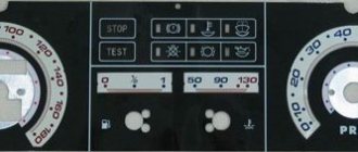
Diagram and pinout of the instrument panel (dashboard) VAZ-2113, 2114 and 2115
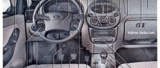
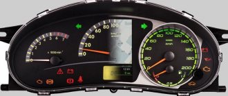
Designations of icons on the instrument panel (dashboard) of VAZ-2113, 2114 and 2115
1 – coolant temperature indicator. 2 – tachometer; 3 – control lamp for left direction indicators; 4 – control lamp for right direction indicators; 5 – speedometer; 6 – fuel level indicator; 7 – fuel reserve warning lamp; 8 – side light indicator lamp; 9 – warning lamp of the service brake system; 10 – control lamp for high beam headlights; 11 – reset button; 12 – mileage indicator; 13 – warning lamp for turning on the hazard warning lights; 14 – “check engine” warning lamp; 15 – time and temperature indicator; 16 – battery charge indicator lamp or battery lamp; 17 – parking brake warning lamp; 18 – oil pressure warning lamp; 19 – reserve;
Pinout of the instrument panel (dashboard) VAZ-2113, 2114 and 2115
Pinout of instrument panel pads (instrument) VAZ-2113, 2114 and 2115
To ambient temperature sensor - cyan-magenta
Tachometer (low voltage input from ECU) - brown/purple
Fuse F16 (to terminal 15 of the ignition switch) - orange
Tachometer (high voltage input from coil) - yellow
To fuse F3 of the mounting block (+battery) - white-purple
System problems
Summarizing the experience of drivers, the most common problems occur in the ignition switch. The limit switch in it should receive 12 volts. Sometimes it is the installers who confuse the diagram, after which the BSK not only does not see the door, but also does not work at all. To check functionality, you must disable the limit switch. If the BSK turns on, but does not see the door, then the problem is here.
For other cases, you will have to resort to checking the systems one by one according to the pinout diagram:
Instrument cluster Key switches On-board control system Trip computer External mirror control unit Control of interior ventilation and heating Fig. 1.2. Controls The location of the controls is shown in Fig. 1.2. 1 – front door glass blower nozzle. 2 – lever for switching direction indicators and headlights. 3 – sideways.
Rice. 1.3. Instrument cluster 1 (Fig. 1.3) – coolant temperature indicator. The transition of the arrow to the red zone of the scale indicates overheating of the engine. In this case, check the operation of the thermostat and electric fan of the cooling system. 2 – tachometer. Indicates the engine speed. The yellow zone of the scale indicates the engine operating mode is high.
1.2.3 Key switches
Switching on and off consumers is done by sequentially pressing the switch key. When the exterior lighting is turned on, the key symbols are illuminated: – side light switch. The side lights are turned on and off by successively pressing the button. When the side lights are turned on, the indicator in the button itself lights up; – headlight switch. By pressing the key.
Rice. 1.4. On-board control system The on-board control system block is shown in Figure 1.4. 1 – indicator of insufficient oil level in the engine crankcase. Lights up orange if the oil level in the engine crankcase has dropped below the “MIN” mark of the indicator. Before adding oil, check whether there is any oil leakage due to loss of tightness of the lubrication system. 2.
Rice. 1.5. Trip computer The trip computer (Fig. 1.5) is installed on some of the cars produced and is designed to measure, accumulate and display one of seven parameters on a digital display: – fuel consumption (current, average, total); – average speed; – distance traveled; – current time; – travel time. When you press the button.
Some of the cars produced are equipped with electrically controlled exterior mirrors. WARNING When the ignition is turned off, the trip computer indicator turns off, but the accumulated information and clock progress are saved. If the battery is disconnected, all accumulated information is lost. When the voltage drops in the on-board network.
Rice. 1.7. Interior ventilation and heating controls: 1 – heater electric fan switch; 2 – lever for supplying air to the driver’s and passengers’ foot area; 3 – heater tap control lever; 4 – air supply lever to the windshield; 5 – nozzle for blowing glass of the front doors; 6 – rear window heating switch; 7 – side nozzle; 8 – central nozzles; 9 – lever.
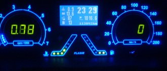
The purpose of the instrument panel (ID) on any car is to inform the driver about the operating status of the main components and mechanisms. Depending on the car brand, the purpose of the PP elements may be different. In this article we will talk about what the indicators installed in the instrument panel are responsible for in the VAZ 2115 and how to replace the device if necessary.
Icons on the instrument panel of the VAZ 2115
The picture becomes interactive when you hover the cursor.
- Antifreeze temperature scale. When the needle is in the red zone , the engine is overheating.
- Crankshaft rotation scale. When the arrow is in the red zone, the maximum speed has been reached.
- Left turn signal.
- Right turn signal.
- Vehicle speed scale.
- Gasoline level scale in the tank.
- The “gas station” signal appears when 6-7 liters of fuel remain in the tank.
- The “lamp” signal appears when the outside light (dimensions) is turned on.
- The "exclamation mark" signal appears when the brake fluid drops below the minimum level.
- The headlight signal appears when the high beams are turned on.
- A button that serves to set the clock and reset the daily mileage.
- Odometer.
- The red triangle signal appears when the emergency lights turn on.
- The “engine” signal (check) flashes during startup and appears when problems are detected in the engine.
- Clock/temperature. Switched by button 11.
- The “battery” signal appears when problems with the battery charge are detected (the alternator belt is broken or loose, the alternator is out of order, etc.).
- The “P in a circle” signal appears when the car is put on the handbrake.
- The "lamp" signal appears when there is insufficient engine oil pressure.
- Backup lamp.
The symbols on the dashboard are covered more fully in the blog.
Did you like the answer? Yes 1 No
- VAZ (Lada) 2113/2114/2115 Icons on the instrument panel of VAZ 2114
Why does the oil pressure light come on in the VAZ 2114/2115
There are several likely reasons why this car light suddenly comes on. And only based on an accurate determination of the cause can the necessary actions be taken to eliminate the malfunction.
The indicator may light up in two cases:
at engine idle speed;
Each of these cases has its own causes of malfunctions.
The indicator in the form of an oil can lights up in situations where there is any problem with the oil pressure
The light came on at idle
The oil pressure light may come on (or blink) at idle, and if you press the gas pedal, the icon will immediately go out. In this case, the most likely causes of malfunctions are the following:
the crankshaft liners are worn out: the oil pressure will drop due to the fact that the gap between the thinned liner and the car’s connecting rod has increased;
the oil receiver mesh is severely clogged: one of the most common reasons why a light bulb suddenly lights up. Various types of sediment are gradually deposited on the surface of the engine sump. At the moment when there are too many deposits, the pump can no longer supply enough oil to operate the engine;
wear or any problems in the oil pump: another probable reason why the indicator may light up on a VAZ 2114/2115. Due to a breakdown of the pump itself or any part of it, oil does not enter the engine in the required quantity;
the sensor is faulty: it is quite possible that the oil level and the engine itself fully meet their basic characteristics, and the problem lies in the sensor;
the wiring is shorted: problems in the car’s electronic system can also cause the engine oil supply system to not operate correctly.
The oil can indicator light came on while driving.
In cases where the oil pressure light suddenly comes on while the car is moving, it is advisable to stop immediately. Probably the following failure or breakdown occurred:
the oil level in the engine unit is below the Min mark;
the oil filter could be clogged - this leads to the fact that the pressure invariably decreases;
it's time to change the oil - in cases where the car owner does not replace the substance in the engine for a long time, it loses its working properties.
We study the designation of icons on the instrument panel of the VAZ 2114
The panel itself contains three types of elements:
- Indicator lamps indicating the amount of consumables required for the operation of the car - gasoline. oils, brake fluid, etc.;
- Speedometer and tachometer;
- A control element for switching the speedometer operating mode.
Also, the concept of “instrument cluster” usually includes levers for turning on turn signals, buttons for controlling headlights, and a stove. and other machine communications.
The VAZ 2114 dashboard diagram looks like this:
From this article you will learn the designation of the icons on the dashboard of the VAZ 2114, the reasons for the indicators to light up, as well as the measures that need to be taken to eliminate the problems that have arisen.
Why do light bulbs fail?
How to remove the instrument panel on a VAZ 2114
The main reason for the relatively quick burnout is rather difficult operating conditions. Reduce resource:
- voltage fluctuations;
- vibration;
- overheating (in a closed space of the instrument panel this is normal).
In addition, filaments have a short service life of only 1500 hours.
In addition, lamps may stop working due to:
- wiring damage;
- destruction of board tracks;
- contact oxidation;
- blown fuses due to short circuit, etc.
For this reason, before replacing a light bulb in a Lada 2114, it is advisable to find out why it stopped working. Until the root cause is identified, the situation cannot be corrected.
Basic panel elements
The main place on the dashboard is reserved for the tachometer and speedometer, the fuel quantity sensor and the current fluid temperature in the cooling system. Let's look at the main symbols on the VAZ 2114 panel in more detail.
The VAZ 2114 tachometer is a pointer device, the signal to which is sent by the on-board computer of the fourteenth. The tachometer displays data on the number of revolutions of the crankshaft at the current time. The tachometer is divided by scales into 5 units, every second of which is digitized. The maximum numerical value of revolutions is 80.
To find out the actual engine speed when the car is moving, the tachometer indicator must be multiplied by 100. For example, if the arrow is located at 40, then the crankshaft is performing 4000 revolutions per minute.
The manufacturer has indicated a critical speed value, upon reaching which the engine of the fourteenth may fail due to excessive load. It is highlighted on the device with red shading; this value ranges from 6000 to 8000 rpm.
Under the tachometer there is an electronic window, which displays data about the current time and ambient air temperature.
The fourteenth has an induction dial speedometer, which is located on the right side of the dashboard. The speedometer is also divided into sectors, the division size is 10 kilometers. The maximum mark is 200 km.
Installation and repair instructions
To replace the PP on a VAZ 2115 tuning, taking into account the pinout, follow these steps:
- First, disconnect the cable that goes to the cigarette lighter.
- Dismantle the control panel cover; to do this, find two self-tapping screws at the edges and unscrew them. Also unscrew the screws that secure the PP at the top and bottom.
- Dismantle the cover; this will require some effort. The pad itself is held on by clamps, so the plate will need to be rocked a little.
- Next, disconnect all the wires that are connected to the control panel - these are the connectors for the light alarm, clock, speedometer, fuel level sensor, etc.
- Dismantle the control panel; to do this, you will need to unscrew four more bolts on which it is fixed. Be careful at this stage - do not damage the wiring.
Actually, at this point the procedure for dismantling the control panel can be considered complete. If you need to change light bulbs, simply remove the sockets and install new indicators. To remove the cartridges you will need to turn them counterclockwise, do this carefully so as not to damage them. Further assembly is carried out in reverse order.
Loading …
Indicator paws
Also, the instrument panel on the VAZ 2114 has a block of light indicators, which includes the following icons:
Let's look at the designation of the icons on the instrument panel in more detail:
- An indicator that displays information about the current engine oil level. When the amount of lubricating fluid is critically low, the light turns orange. Oil must be added immediately after this indicator becomes active;
- This indicator indicates a low amount of working fluid in the windshield washer reservoir. The tank is designed for 5 liters of liquid, the indicator turns on when its quantity drops below 1 liter;
- Fluid quantity sensor in the engine cooling system. One of the most important indicators that needs to be closely monitored;
- Indicates the presence of unlocked doors. Lights up red;
- An indicator that lights up if the dimensions or brake lights are out of order. The active indicator color is red;
- A light that lights up in case of critical wear of the brake pads (1.5 mm). Lights up from the moment you first press the brakes until the car is turned off;
- An indicator indicating that the driver is not wearing seat belts.
An exclamation mark on the instrument panel of a VAZ 2114 can light up in two cases: when the car’s starter is turned on, and when the brake fluid level is low. As a rule, the reason is in the second option.
To eliminate the problem, completely fill the tank and check the contacts of the TZ level sensor, which are located on the container lid, for oxidation.
If the engine icon on the panel is on, it means something is wrong with the power unit of the fourteenth. There are many reasons why the Check Engine light comes on; it often stays on even when there are no visible faults. It is best to go to a service station for diagnostics, this way you will be protected from possible problems.
Possible faults
The instrument cluster of the VAZ 2115, like any other component of the car, is a device susceptible to various malfunctions.
In this case, there are not so many of them and they are all connected with the electrical part:
- If the instrument panel does not work, there may be several reasons. Either this is poor contact between the device and the ECU, which can be solved by replacing the plug or cleaning the contacts, or a malfunction of the control panel itself, or “glitches” in the operation of the control unit. Typically, the device’s inoperability appears after the PCB has been dismantled and installed in place. In this case, the reason, most likely, is a poor connection of the contacts, so all connectors need to be reconnected, taking into account the pinout.
- Some devices do not work - tachometer, speedometer, fuel level controller. The problem can be either electrical and consist of poor contact, or mechanical (breakage of the speed sensor, fuel level in the gas tank, etc.). Usually replacing the regulators will solve the problem.
- The backlight of the VAZ 2115 instrument panel does not work. If all the bulbs immediately refuse to work, the reason, again, needs to be looked for in the electrical part - maybe a wire has simply come loose somewhere. If only one or several lamps have burned out, then they simply need to be replaced (a video about the installation of a tuned device in a dozen VAZs was made by Pavel Ksenon).
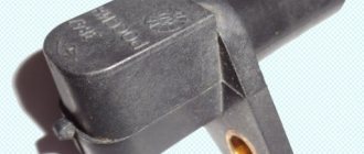
Bottom column of warning lamps
Let's look at the icons that fill the bottom of panel 2115, from left to right. An icon in the form of two vertical bars and a diagonal stripe indicates a reserve indicator. The container icon with a drop of liquid lights up when the oil level in the engine lubrication system is too low.
The letter P, described in a circle, lights up when the car is placed on the handbrake. The battery charge lamp should light up when you start the engine and then go out immediately. If the icon does not glow after starting the engine, then the on-board computer has detected problems with the battery charge, alternator or V-belt.
The CHECK ENGINE icon is displayed on the panel to indicate normal engine starting. It should also go out immediately after the engine is started. If this does not happen, it means that the ECU has detected a malfunction in the operation of the power unit. Above this icon is an indicator that the hazard warning lights are operating.
The icon in the form of a headlight with a blue border means that the high beam headlights are on. The symbol in the form of an exclamation mark in a circle informs that the brake fluid has reached the minimum permissible value. In the lower right corner there is a green light bulb icon. It lights up simultaneously with the side lights turning on and means that the optics are activated. Above it is an icon in the form of a gas station.
The “gas station” indicator lights up when there are no more than seven liters of fuel left in the fuel tank, and the VAZ 2115 needs refueling after covering 20–30 km.