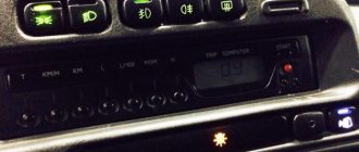
For greater convenience, the button for turning on the low beam headlights and the button for turning on the dimensions of the VAZ 2114 are made in pairs and are located on the car's European panel. Both are equipped with additional built-in LEDs (two for backlighting and one indicator for side lights).
As a rule, there are no problems with the operation of these buttons, but if necessary (for example, in case of breakdown), you should know how to replace them.
Everything is done in the following order:
- Remove the cover under manual control (removed simply by hand, without tools).
- Pull the buttons inward by pressing them from the inside.
- Gently pull the button, wiggling it slightly, and remove it from the shoe.
- Install the new button into the shoe.
- Place the buttons back into the panel.
As you can see, replacement can be done almost instantly, without much effort and without the use of special tools.
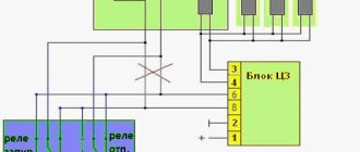
Another important point that should be highlighted is the pinout of the button to fit the dimensions of the VAZ 2114. It may be needed, for example, when replacing an old type button with a button for a Europanel.
You can see this more clearly in the following diagrams: for old style buttons
for new type buttons
All letters indicated in the diagram correspond to the output contacts of the buttons and have markings similar to them, and the colors of the wires are indicated by letter abbreviations.
In addition, the pinout of the VAZ 2114 light button can also help in troubleshooting problems related to the operation of the buttons themselves, for example, if the backlight of one of them does not work.
Please note that the contacts:
- 6-B or 5-B - are responsible for the operation of the low beam indicator;
- А-В — illumination of the low-beam headlight button;
- C-D—size inclusion indicator;
- ED — illumination of the button for turning on the size.
Scheme for switching on headlights, side lights and turn signals for VAZ-2113, 2114 and 2115
Headlight switching diagram for VAZ-2113, 2114 and 2115
Scheme for switching on headlights and fog lights:
1 – headlights; 2 – mounting block; 3 – headlight switch; 4 – ignition switch; 5 – external lighting switch (fragment); 6 – fog lamps in the internal rear lights; 7 – fog light switch with control lamp; 8 – indicator lamp for high beam headlights in the instrument cluster; K8 – headlight high beam relay; K9 – relay for low beam headlights; A - the order of conditional numbering of plugs in the headlight block; B - to power supplies
Scheme for switching on the side lights of VAZ-2113, 2114 and 2115
External lighting switching diagram:
1 – side light lamps in headlights; 2 – engine compartment lamp; 3 – mounting block; 4 – engine compartment lamp switch; 5 – ignition switch; 6 – external lighting switch (fragment); 7 – indicator lamp for external lighting in the instrument cluster; 8 – side light and brake light lamps in the external rear lights; 9 – license plate lights; 10 – instrument lighting regulator; 11 – brake light switch; 12 – on-board control system unit; K4 – relay for monitoring the health of lamps (contact jumpers are shown inside the relay, which must be installed in the absence of a relay); A - to power supplies;
Scheme for switching on direction indicators and hazard warning lights for VAZ-2113, 2114 and 2115
Diagram for switching on direction indicators and hazard warning lights:
1 – direction indicator lamps in headlights; 2 – mounting block; 3 – ignition switch; 4 – alarm switch; 5 – side direction indicators; 6 – direction indicator lamps in the external rear lights; 7 – instrument cluster with turn signal indicator lamps; 8 – direction indicator switch; 2 – relay-interrupter for direction indicators and hazard warning lights; A - to power supplies
Car modifications 2114
VAZ-21140 . Modification with an 8-valve injection engine VAZ-2111, 1.5 liters and 77 horsepower. Serial production from 2003 to 2007
VAZ-21144 . Modification with an 8-valve VAZ-21114 engine, 1.6 liters and 81.6 horsepower. Years of serial production: 2007-2013.
VAZ-211440 . Another modification released in 2007, it was equipped with a VAZ-11183 engine with a volume of 1.6 liters and a power of 82 horsepower. The car was discontinued in 2013.
Why change the backlighting of individual buttons on the VAZ 2114 dashboard
On the VAZ 2114, the illumination of the buttons for controlling the dimensions, low beam, front and rear fog lights, as well as the rear window heating is green from the factory. Over time, many owners get tired of this glow and there is a desire to replace it, make it non-standard. After making a decision about such modifications, you need to decide: do this work yourself or contact the service. Since the process of replacing button backlighting is not a complicated procedure, in most cases, car owners carry out such an upgrade with their own hands.
Do-it-yourself overexposure of buttons on a VAZ 2114
Replacing the standard button backlighting on a VAZ 2114 will require the preparation of certain tools, materials, as well as some time. To work you will need the following list of necessary things:
- soldering iron with a thin tip;
- solder;
- tweezers;
- small knife or flat screwdriver;
- LED elements of the desired color.
Which LEDs and in what quantities should I buy?
The buttons installed on the dashboard of the model in question come in old and new styles. In the first case, small light bulbs or LEDs are used as a backlight element, and in the second, boards with sealed SMD LEDs are used.
Each button is equipped with two LED elements: one is responsible for illuminating the button itself, and the second indicates the activation of a particular function. The exception is the low beam headlight button - it does not have a power indicator LED. Therefore, if you plan to replace the LEDs on all five buttons, you will need to purchase 9 backlight elements. The type of the latter can be determined only after disassembling the button. The old model requires 12 V LEDs with a diameter of 3 mm. The new sample uses elements marked 0805. When using standard LEDs, it is recommended to additionally install a resistor with a resistance of 500 Ohms to 1 kOhm along the power circuit (directly in the button), which will prevent the element from burning out.
It is better to purchase LEDs with a small margin, since there is a possibility of damage to the element during installation.
How to remove buttons
To remove the buttons on the front console, do the following:
- Remove the negative terminal from the battery.
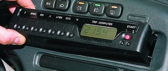
- We take out the plug of the on-board computer or the BC itself, if it is installed. To do this, just hook it with your finger and pull it towards you.
Replacing the backlight of the front panel buttons
Since replacing LEDs on old and new button versions is somewhat different, each process should be considered separately.
Overexposure of old-style buttons
After removing the buttons from the instrument panel, perform the following sequence of actions:
- Pull the top of the button and remove the lid that is pressed.
The LEDs on all instrument panel buttons change in the same way.
Overexposure of new buttons
On modern buttons we change the LEDs this way:
- We disassemble the button, as in the previous paragraph.
- After opening we find a board with installed LEDs. We determine the polarity of the elements and solder them with a soldering iron with a thin tip.
To make it easier to replace LEDs, the board can be removed from the button. Depending on the button itself, the board can be inserted or soldered onto the legs.
Video: overexposure of VAZ 2114 buttons
Modernization of the buttons for turning on the headlights and low beam
The buttons for turning on the headlights and low beam headlights are made as a single element. The absence of an LED indicating that the headlights are on low beam causes inconvenience to many motorists. This is due to the fact that it is often unclear whether the headlights work or not. To solve this problem, they resort to modernizing the button. In addition to the tools listed above, you will need a similar button from which the necessary parts will be removed. The finalization process itself consists of the following steps:
- Remove the button from the panel.
Video: refining the low beam switch button
Installation methods
There are several options for equipping your vehicle with a fog light system. The choice depends on your personal preferences and capabilities.
Way
Peculiarities
Buy a bumper with built-in PTF
Such bumpers are bought at a tuning studio, where everything will be connected and hooked up for you. The disadvantage of this option is the high cost.
Buying a bumper from a VAZ 2115 and installing it yourself
To do this, you will need to purchase a bumper from the previous model, which has holes for the fog lights. All that remains is to find a suitable set of PTFs and install them
Purchase of PTF and finishing elements - glass
Today this method is in great demand, as it allows you to do the installation yourself for little money.
The standard PTF kit includes several items:
When choosing a kit, pay attention to whether the headlights fit the shape of the glasses, that is, the front elements.
Standard kit
Today, VAZ 2114 owners who want to install fog lights are recommended to choose rectangular kits from the Kirzhach company. Used when factory-installed PTF on expensive versions of the model.
Xenon in PTF
Many car owners are thinking about installing xenon lamps in their fog lights. This is good? Not really.
The fact is that when xenon is installed in the PTF, the focus is disrupted. The operating principle of xenon is slightly different from traditional Kirzhach type lamps.
Standard PTFs are designed for certain types of lamps, so they cannot cope with xenon. As a result, the reflector experiences excessive reflection, the rays are refracted and the light is washed out. Where does this lead? To blind oncoming drivers.
The xenon version is not a practical or good solution. Therefore, we recommend that you refuse it.
Another option is a combination of xenon and yellow fog lights. You will need H1 xenon bulbs, which are mounted in the bottle cap and only then inserted into the headlight. This way the light beam has smoother edges, does not blind oncoming traffic, and better illuminates the roads in bad weather. Only after installing this combination lighting, make sure that your headlights do not blind oncoming cars.
Experience of car enthusiasts
There are buttons with both lamps and diodes, there is a choice. The resistors are soldered directly into the diode, this is AvtoVAZ know-how. You can see it under a magnifying glass. And change it to a regular one, that is, a small one, they are durable. And the small diodes I bought for tuning ended up almost all flying off too.
Zbugz
https://www.lada-forum.ru/index.php?showtopic=16929
LEDs with a built-in resistor are sold in buttons for sidelights, fog lights, etc. (cost about 30 rubles). The light bulb is simply replaced with an LED. The light filter is removed from the button.
Killer Speed
https://www.autolada.ru/viewtopic.php?t=60935
Everything is very simple in fact))) I held my head until I opened it and figured it out!))) My car is 9 years old. Even these buttons have diodes or whatever they are called, instead of light bulbs. So, I sat and thought and just took a drill with a small drill and drilled the hell out of there and soldered what I needed to the antennae, that’s all))))) And the backlight for the low beam is complete garbage. Even I, a person who doesn’t understand anything about car electrics, figured it out.
MillerLight
https://www.2114.ru/forum/showthread.php?p=154984
Having decided to relight the buttons on a VAZ 2114, it is not necessary to contact the service: you can do the modifications yourself. The procedure is not complicated and requires a minimum list of tools and basic knowledge in electrical engineering. By following the step-by-step instructions, relighting the buttons will not be difficult.
Installation and configuration instructions
Installing emergency lights on a VAZ 2101 is not a particularly difficult task; almost anyone can cope with it. To properly connect the emergency lights to a VAZ 2101 with your own hands, you need to prepare everything you may need to complete the task.
Set of tools and materials
So, what you need to prepare before starting the process:
- Locksmith tools, including wrenches, screwdrivers, pliers, etc.
- Insulating tape.
- Four-contact light signal relay from the “Six”.
- Six-pin button for activation.
- Five meters of installation wire (video by Alex Gordon).
https://www.youtube.com/watch?v=NoA5L2Z_WA0
Work execution algorithm
So, let's start the process:
- First you need to remove the center console. To do this, you need to unscrew the bolts that secure the trim to the steering column. You will also need to remove the side trims of the windshield pillars.
- Having done this, you can remove the instrument cluster. Be careful not to damage the device.
- Next, disconnect the wires from the light bulb that illuminates the glove compartment. Then unscrew the bolts that secure the sides of the glove compartment to the control panel, as well as the bolts that secure its lower part. After unscrewing all the screws, the glove compartment itself can be removed.
- Now you need to remove the screws that secure the bottom of the dash to the front cross member. Then the nuts of the upper fastening are unscrewed; it is best to reach them through the technological opening of the glove compartment.
- After completing these steps, you can remove the handles from the stove control panel. To do this, at the junction of the lever with the handle, use a screwdriver to bend the lower part of the upper handle, and at the lower handle, you need to bend the upper part.
- Next, you need to disconnect the connectors with wires from the control panel backlight switches, side lights, and also the stove. Then, using a wrench, you need to unscrew two more bolts that secure the fastenings of the stove control levers. After completing these steps, you will be able to dismantle the control panel.
- Now let's move on to installing and connecting the main elements. First, decide on the location of installation of the system power button. It should be installed on the center console so that the driver can reach it as quickly as possible if necessary. It’s still too early to install the button, but you need to decide on the installation location now, since this will determine how much wire you need. Now remove the old turn signal relay from the car and disconnect the three cables from it - usually they are colored black, gray-white and orange.
- Next, take a new six-wheel relay. The second contact of the relay must be connected to the wire that was removed from contact L on the turn signal relay, as well as to output 7 of the button.
- The first contact of the relay must be connected to the fourth contact on the button itself. The third contact is connected to the cable disconnected from contact P on the turn signal relay. Then you need to connect the cable from the fourth contact to ground, that is, the body of the vehicle - it is best to connect it to the relay fixing nut.
- The next step is to connect the button itself. The fourth contact of the button should be connected to the first contact of the relay used. Its second contact must be connected to the cable that was disconnected from the positive contact of the rotary relay. The seventh contact is connected to the second contact of the relay, and the first and third contacts are connected to the steering column turn signal switch; in this case, the order of connection does not matter.
- Now all you have to do is connect the eighth pin to any positive cable; alternatively, you can wedge it into the electrical circuit from the cigarette lighter. If you decide to connect the plus directly to the battery or generator unit, the circuit will need to be protected with a fuse.
- At this point, the installation procedure can be considered complete. All you have to do is securely fix the wiring to prevent chafing of the cables. Reinstall all previously removed interior trim elements, center console, glove compartment, etc.
1. Relay connection diagram
2. Diagram of a penny turn switch
Price issue
The cost of an emergency warning button for a Kopeyka ranges from 100 to 400 rubles on average. As for the relay, its cost varies around 200-400 rubles.
Button for dimensions and low beams of VAZ 2114: features and replacement
For greater convenience, the button for turning on the low headlights and the button for turning on the dimensions of the VAZ 2114 are made in pairs and are located on the European panel of the car. Both of them are equipped with additional built-in LEDs (two for backlighting, as well as an indication diode for side lights).
As a rule, there are no problems with the operation of these buttons, but if necessary (for example, if they break), you should know how to replace them.
Everything is done in the following order:
- Remove the plug under the button panel (it can be removed simply by hand, without tools).
- Push the buttons into the interior by pressing them from the inside.
- Gently pull the button, rocking it slightly, and remove it from the block.
- Install a new button into the block.
- Place the buttons back into the panel.
As you can see, the replacement can be done almost instantly, without applying any great effort or using a special tool.
Another important point that should be highlighted is the pinout of the VAZ 2114 size button. It may be needed, for example, when replacing an old type button with a button for a Europanel.
You can most clearly see it in the following diagrams: for buttons of the old type for buttons of the new type All letters indicated in the diagram correspond to the output contacts of the buttons and have similar markings to them, and the colors of the wires are indicated by letter abbreviations.
Also, the pinout of the VAZ 2114 light switch button can help when troubleshooting problems in the operation of the buttons themselves, for example, if the backlight of one of them does not work.
In this case, it should be taken into account that the contacts:
- 6-V or 5-V - responsible for the operation of the low beam indicator;
- А-В — illumination of the low-beam headlight button;
- С-D — indicator for turning on dimensions;
- E-D — illumination of the button for turning on the dimensions.
How to install a PTF: necessary materials and tools
Installation of fog lights, regardless of the chosen installation method, requires the presence of certain parts and tools, without which it is impossible.
What are the button and relay for?
A special button and relay are a must - “fog lights” are very powerful equipment for car electrical wiring. The absence of such parts can provoke high current loads on the terminals and the ignition switch, which will cause burnout of contacts, damage and overheating of the insulation protection and short circuit with failure of the electrical network.
In order to install fog lights on a VAZ, you need to assemble certain parts in advance or purchase a ready-made kit. The cost of such a set rarely exceeds one thousand rubles.
The PTF kit includes:
- wires with blocks and terminals for a specific VAZ model. There are three of them as standard: one connects the headlights, the second goes to the relay from the switch, and the third goes from the relay to the fuse box;
Set of wires with terminals and blocks for installing PTF
Fog lamp relay for VAZ 2113, 2114, 2115
Button to turn on PTF on Lada
Plastic ties and clips that secure wires
PTF for VAZ 2115
Which PTFs should you prefer? The headlights themselves are chosen by the driver to his taste, but the main thing when choosing is not to make a mistake with the power, so as not to overload the generator and the car’s electrical wiring. It is better not to purchase headlights with xenon: the generator has a certain power reserve, but is not designed for too high loads. Regular light bulbs will be sufficient.
Reworking the low beam button
As already mentioned, the button for turning on the low beam and the button for the dimensions of the VAZ 2114 are combined and located in pairs. Their main drawback, which most car enthusiasts point out, is the absence of a power-on LED on the low-beam headlight button.
This problem is quite serious, since very often it becomes unclear whether the headlights are working or not (especially during daylight hours). You can solve this by upgrading the button yourself.
For this you will need:
- a button that will be redesigned;
- the second button is the same - donor;
- soldering iron or (better) soldering station.
The button modification should be carried out according to the diagram shown here. Resoldering the LED itself from one board to another is highly not recommended, since this requires a soldering station equipped with a hair dryer, a special flux and high skill in working with them.
First, we need to remove the main button from the car panel (how to do this has already been discussed above).
After it is removed and disconnected from the wires, perform the following operations:
- remove the keys by prying them off with a flat screwdriver;
- we disassemble the body of the buttons by pressing the latches with a screwdriver (the buttons themselves at this moment must be in the “on” position);
- we see that the sidebar button has two diodes (backlight and indication), and the low headlight button has only a backlight button;
- remove a pair of legs and a pair of contacts from the donor button;
- we rearrange them into the free spaces on the working button;
- remove the board from the donor button with two diodes and insert it into the working button instead of the board with one diode;
- solder the board to the legs that were added;
- make a hole in the button cover (this can be done with a sharp knife or simply punched with a flat screwdriver).
The junction of the newly installed legs and the new board must be well soldered. Otherwise, the button may quickly fail or not work correctly.
After all these operations have been completed, all that remains is to assemble everything in the reverse order and install the upgraded button in its place (during installation, it is important that all the mini-latches on the case fall into place).
Requirements for installing fog lights
The installation rules are specified in the traffic rules GOST 8769-75. If the design of the car does not provide ready-made places for installation, they can be taken out separately, or the bumper can be remade. The last option is somewhat complicated, because this modification leads to changes in the design of the vehicle, which equates to a partial re-equipment.
The previously mentioned standard dictates the rules for installing PTF.
- The number of fog lights is no more than two.
- There should be no more than 40 centimeters of distance between the side plane and the light source.
- The minimum installation height is 25 centimeters from the road surface.
- The fog light opening should be located lower than the top of the low beam opening.
- The fog light is only allowed to be turned on in conjunction with the headlight bulbs.
- The viewing angle is 15 degrees in the vertical plane and 45 degrees in the horizontal. The maximum deviation from the specified values is ten degrees.
Note! If there are no regular places where you can install PTFs, they will have to be selected manually. After all, this procedure must be performed correctly, in accordance with the requirements of current legislation.
One more thing. Once installation is complete, you may sometimes need to adjust the headlights. This is necessary so that the angle at which the light flux falls on the road is correct.
Pinout of low beam button VAZ 2114
Answer to the request on request in the topic pinout of the VAZ 2114 dimensions button - you are welcome. Techniques and technologies for car repair in garage conditions. How to repair a car yourself at home. We will help you with repairs and repair the car yourself. We know how to restore a car with minimal investment. I have attached video instructions.
Category: DIY repairs
Laughter on topic: - And we are in first place in the medal standings! - And we overthrew the president. - Damn...
Published by Admin: at the request of Istvan
Criticism of the car owner: Appearance, dynamics, handling, excellent brakes, comfortable driving position, spacious interior, excellent visibility, warm stove, starts in any frost, corrosion resistance, good sound insulation, large trunk, full-size spare wheel, price.
Now, in accordance with the current rules, it is necessary to drive in the daytime with low beams or fog lights on. If your VAZ 2109 does not have fog lights installed, in this article you can see how to install them. And if an indication of turning on the PTF is usually present in the car (in a Lada Samara with a high panel it is a light next to the button for turning on the PTF, with a Europanel - on the button itself), then turning on the low beam is not displayed in any way on the dashboard. The light spot from the low beam on the road when it is light outside is also not visible, so you can quickly determine whether the low beam is on during the day only by the position of the button to turn them on, which is not informative enough.
Let's set ourselves the goal of installing an indication for turning on the low beam headlights on the Lada Samara ourselves.
Let’s immediately make a reservation that in this article we will consider the option of installing an indication for turning on the low beam on the Samara europanel, where the following button is responsible for turning on the dimensions and low beam:
Let's get started. To modify the button, we will need the same donor button, since it lacks the indication LED itself, the contact antennae and the contacts themselves.
The antennae and LED are removed from the donor button and installed in the button being modified quite easily. But you will have to tinker with the contacts, since they have teeth that do not allow the contact plates to be freely removed from the button. You'll have to use a tool. You may have to cut the donor button to remove them.
The modified button looks like this:
Now we need to finalize the connection, we need to solder these wires to the contacts on the button on the contact side, either on the button itself or in the connection connector.
However, the window for the LED indicating that the low beam is on is painted over, and practically no light penetrates through it. You need to remove the paint from it using a thin screwdriver.
Improvement of the illumination of the low beam key for the VAZ 2109
A slight modification of the dimensions/low beam switch button can also be done on a VAZ 2109 with a high/low panel, namely, you can make the backlight of the button itself (light bulb icon) light up when the ignition is turned on. This makes it easier to find the button by touch in the dark, especially on a low panel.
In the picture we see the low beam button of the VAZ 2109 on the reverse side. In order for the backlight of this key to light up when you turn the key, you need to place a jumper on the “+” bulb from pin 3 (power supply from the ignition switch), if you do this without a diode, then the low beam will light up even when the ignition is off. Next, so that the entire panel does not burn, we disconnect the wires that previously came to the “+” bulbs (2 wires are white with black a and b), and everything is fine, but now if you turn on the headlights and turn off the ignition, the button illumination will also disappear To this end, we also connect wires a and b through a diode to the plus of the light bulb. As a result, when you turn the key, the button lights up, and when the ignition is turned off, the button does not go out until it is turned off. For ease of installation, all operations are performed on the connector to which the button is connected.
For greater convenience, the button for turning on the low headlights and the button for turning on the dimensions of the VAZ 2114 are made in pairs and are located on the European panel of the car. Both of them are equipped with additional built-in LEDs (two for backlighting, as well as an indication diode for side lights).
As a rule, there are no problems with the operation of these buttons, but if necessary (for example, if they break), you should know how to replace them.
Everything is done in the following order:
- Remove the plug under the button panel (it can be removed simply by hand, without tools).
- Push the buttons into the interior by pressing them from the inside.
- Gently pull the button, rocking it slightly, and remove it from the block.
- Install a new button into the block.
- Place the buttons back into the panel.
As you can see, the replacement can be done almost instantly, without applying any great effort or using a special tool.
Another important point that should be highlighted is the pinout of the VAZ 2114 size button. It may be needed, for example, when replacing an old type button with a button for a Europanel.
You can most clearly see it in the following diagrams: for buttons of the old type for buttons of the new type All letters indicated in the diagram correspond to the output contacts of the buttons and have similar markings to them, and the colors of the wires are indicated by letter abbreviations.
Also, the pinout of the VAZ 2114 light switch button can help when troubleshooting problems in the operation of the buttons themselves, for example, if the backlight of one of them does not work.
In this case, it should be taken into account that the contacts:
- 6-V or 5-V - responsible for the operation of the low beam indicator;
- А-В — illumination of the low-beam headlight button;
- С-D — indicator for turning on dimensions;
- E-D — illumination of the button for turning on the dimensions.
Installation
The PTF installation process can be divided into three main stages:
- Installation of headlights;
- Network connection;
- Functionality check.
So, now let's talk about each of the stages separately.
Installing headlights
Consider the option of installing PTF on a standard bumper. As a result, there are no holes for new optics. You will have to do them yourself.
To work you will need a certain set of tools and materials:
- File;
- Drill and drill bits;
- Electric jigsaw;
- Roulette;
- Marker.
Connection elements
Now right at work.
- First of all, remove the bumper. Work is carried out only if it is disconnected from the seat.
- Remove all dirt from the bumper.
- Make markings for installing future fog optics.
- It is best to install the headlights slightly to the side of the lower air intake. Try to place the PTF strictly under the main optics of your car.
- For decorative glass with outer and inner halves, check. The outer half is decorative, and the inner half is for attaching the exterior and headlights.
- The outside of the glasses has a protrusion on the inside. With such a protrusion, the element must fit into the hole made in the bumper.
- To determine the optimal size, measure the landing flap. This will allow you to make the appropriate marks on the bumper.
- Using an electric jigsaw, the required holes are cut to size and position.
- Save the cut points.
- Therefore, the outside of the glasses should fit tightly into the hole.
- Fog lights are mounted in the resulting holes. For this purpose, the kit includes special mounting bolts.
- Attach decorative glass above the headlights. After this, the bumper can be replaced.
Connection
The device connection diagram must be attached to the PTF. This is not difficult, so even a beginner can understand all the nuances of connecting components to each other.
These gaskets are used to connect the fog lamps, although these lighting units are not factory installed as standard. The wiring from the headlights and the fog lamp relay, which is included in the PTF kit you purchased, is connected to these blocks.
Your job is to make the right connection. They are performed according to the following scheme:
- The wire coming out of pin 87 is grounded, so you need to connect it to the body;
- Pin No. 85 goes to the block marked Ш7 and is connected to connector No. 17;
- Endings numbered 30 and 86 go to block Sh8. In this case, connect pin 30 to connector 8 and cable 86 to connector No. 1;
- After installing the headlights, stretch the positive wire through the engine compartment, since they are connected to the Ш8 block. But these wires must be inserted into connectors numbered 2 and 3;
- Now connect the block to the mounting block and return the block to its place;
- Select an area near the block where the fog light relay will be installed.
Connection result
Button
Now you just need to connect your PTF control system. The fog lights come with a corresponding button that will rest on the seat panel provided by the manufacturer.
PTF button
The manufacturer, namely AvtoVAZ, foresaw this. Therefore, under the panel you will find the control unit. The panel is removed, the corresponding block is placed and a button is attached to it. That's it, the checks are ready.
Examination
The last step is to check the functionality of your PTFs.
To check the functionality of the lighting devices, activate the headlights on the VAZ 2114, then press the button to turn on the fog lights. With the headlights turned off, even when you press the button for the fog lights, they should still go out.
The importance of PTF is difficult to overestimate. They help you see the road better in fog, rain, and snow. Additionally, fog lights are designed to improve the visibility of your vehicle in front and behind it. Therefore, it is strongly recommended to install PTF not only at the front, but also at the rear.
Reworking the low beam button
As already mentioned, the button for turning on the low beam and the button for the dimensions of the VAZ 2114 are combined and located in pairs. Their main drawback, which most car enthusiasts point out, is the absence of a power-on LED on the low-beam headlight button.
This problem is quite serious, since very often it becomes unclear whether the headlights are working or not (especially during daylight hours). You can solve this by upgrading the button yourself.
For this you will need:
- a button that will be redesigned;
- the second button is the same - donor;
- soldering iron or (better) soldering station.
The button modification should be carried out according to the diagram shown here. Resoldering the LED itself from one board to another is highly not recommended, since this requires a soldering station equipped with a hair dryer, a special flux and high skill in working with them.
First, we need to remove the main button from the car panel (how to do this has already been discussed above).
After it is removed and disconnected from the wires, perform the following operations:
- remove the keys by prying them off with a flat screwdriver;
- we disassemble the body of the buttons by pressing the latches with a screwdriver (the buttons themselves at this moment must be in the “on” position);
- we see that the sidebar button has two diodes (backlight and indication), and the low headlight button has only a backlight button;
- remove a pair of legs and a pair of contacts from the donor button;
- we rearrange them into the free spaces on the working button;
- remove the board from the donor button with two diodes and insert it into the working button instead of the board with one diode;
- solder the board to the legs that were added;
- make a hole in the button cover (this can be done with a sharp knife or simply punched with a flat screwdriver).
The junction of the newly installed legs and the new board must be well soldered. Otherwise, the button may quickly fail or not work correctly.After all these operations have been completed, all that remains is to assemble everything in the reverse order and install the upgraded button in its place (during installation, it is important that all the mini-latches on the case fall into place).
How to connect fog lights
The easiest way to connect fog lights is if the car is equipped with standard wiring. In its absence, you will have to manually lay conductive elements. There are two options - through a relay and through a button.
Via relay
To install PTF via a relay, you will need the following tools:
At the same time, you need to take corrugation, heat shrink, electrical tape and terminals. The connection sequence is as follows.
- Find a free space to install the relay. Secure it where it can be easily accessed for repair or replacement.
- Select a place to install the button.
- Measure the length of the power wires. It should be enough for free laying without tension.
- Install a 10-amp fuse and run the finished wire from pin 30 to the positive terminal of the battery.
- From pin 85, remove the wire for the power button.
- Connect the relay to ground using pin 86.
- Install fog lights on the bumper.
- Feed the negative wire from the body and the positive wire from pin 87.
- Check the lighting operation.
Via button
The button should receive voltage from any 12-volt wire. As a rule, power is taken from the plus side lights. The ignition system wiring may be fine.
Connecting the headlights themselves is simple. The red wire carries positive voltage, the black wire carries the ground bolted to the body.
Why change the backlighting of individual buttons on the VAZ 2114 dashboard
On the VAZ 2114, the illumination of the buttons for controlling the dimensions, low beam, front and rear fog lights, as well as the rear window heating is green from the factory. Over time, many owners get tired of this glow and there is a desire to replace it, make it non-standard. After making a decision about such modifications, you need to decide: do this work yourself or contact the service. Since the process of replacing button backlighting is not a complicated procedure, in most cases, car owners carry out such an upgrade with their own hands.
Diagram of the heater and heated rear window
- Mounting block;
- Ignition switch;
- Ignition relay;
- Heater motor switch;
- Additional resistor;
- Heater motor;
- Rear window heating switch with turn-on indicator lamp;
- Rear window heating element;
- K7 - Relay for turning on the heated rear window.
Do-it-yourself overexposure of buttons on a VAZ 2114
Replacing the standard button backlighting on a VAZ 2114 will require the preparation of certain tools, materials, as well as some time. To work you will need the following list of necessary things:
solder;
Which LEDs and in what quantities should I buy?
The buttons installed on the dashboard of the model in question come in old and new styles. In the first case, small light bulbs or LEDs are used as a backlight element, and in the second, boards with sealed SMD LEDs are used.
Each button is equipped with two LED elements: one is responsible for illuminating the button itself, and the second indicates the activation of a particular function. The exception is the low beam headlight button - it does not have a power indicator LED. Therefore, if you plan to replace the LEDs on all five buttons, you will need to purchase 9 backlight elements. The type of the latter can be determined only after disassembling the button. The old model requires 12 V LEDs with a diameter of 3 mm. The new sample uses elements marked 0805. When using standard LEDs, it is recommended to additionally install a resistor with a resistance of 500 Ohms to 1 kOhm along the power circuit (directly in the button), which will prevent the element from burning out.
It is better to purchase LEDs with a small margin, since there is a possibility of damage to the element during installation.
How to remove buttons
To remove the buttons on the front console, do the following:
- Remove the negative terminal from the battery.
- We take out the plug of the on-board computer or the BC itself, if it is installed. To do this, just hook it with your finger and pull it towards you.
Replacing the backlight of the front panel buttons
Since replacing LEDs on old and new button versions is somewhat different, each process should be considered separately.
Overexposure of old-style buttons
After removing the buttons from the instrument panel, perform the following sequence of actions:
- Pull the top of the button and remove the lid that is pressed.
The LEDs on all instrument panel buttons change in the same way.
Overexposure of new buttons
On modern buttons we change the LEDs this way:
- We disassemble the button, as in the previous paragraph.
- After opening we find a board with installed LEDs. We determine the polarity of the elements and solder them with a soldering iron with a thin tip.
To make it easier to replace LEDs, the board can be removed from the button. Depending on the button itself, the board can be inserted or soldered onto the legs.
Video: overexposure of VAZ 2114 buttons
Modernization of the buttons for turning on the headlights and low beam
The buttons for turning on the headlights and low beam headlights are made as a single element. The absence of an LED indicating that the headlights are on low beam causes inconvenience to many motorists. This is due to the fact that it is often unclear whether the headlights work or not. To solve this problem, they resort to modernizing the button. In addition to the tools listed above, you will need a similar button from which the necessary parts will be removed. The finalization process itself consists of the following steps:
- Remove the button from the panel.