Next we will look at how to correctly connect the signaling system on cars of the VAZ 2114 family. The following will be implemented: connection to the central locking, auto start, reading the status of door limit switches. To control the central locking, the VAZ plant produced BUBD modules. If such a module is missing, the task will be simplified - you will not connect the central locking system. The same applies to the case when the driver's door only has a switch, but not an actuator. All tables given here are suitable for the Starline A91 Dialog alarm system, and to set up another system, use the instructions for it.
Connecting the central lock
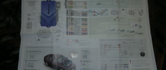
First you need to study in detail the connection diagram for the central locking on a VAZ car - 2115,2114. Finding it is not a problem by searching on the Internet.
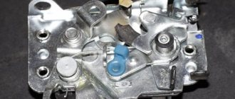
The central locking control module is located on the left under the dashboard. Looking there, you will find six wires coming out of the module housing. To install the alarm, you must disconnect the blue and brown cords. As a result, we get a connection corresponding to the following diagram:
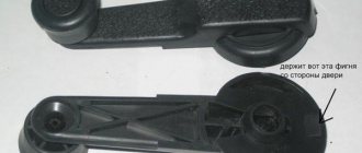
Before connecting the alarm, you should make sure that it is not a toggle switch installed on the driver's door, but a standard actuator with five outputs. Otherwise, you will need to install an actuator, which is quite problematic.
On VAZ -2115,2114 cars, the white wire, which is connected to the seventh terminal, is usually responsible for unlocking. If there are no connections at terminals 7 and 5, then the eighth terminal is connected to the brown cord. It is this cord that is responsible for unlocking in this case.
Terminals number five and six are responsible for locking the lock. This arrangement of contacts is typical for almost all blocks of the “ninth” series.
For some reason, none of the instructions for alarms ever indicate that installation requires the purchase of additional elements.
We will definitely need:
- Two to three 1N4001 diodes per Ampere
- One 1N5401 3 Ampere diode
- Two 4 or 5 Ampere diodes if there are no separate outputs for turn signals.
When installing a Starline alarm system, the task is greatly simplified, since significantly fewer additional parts are needed.
Basic information about the car
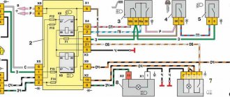
When starting to install the alarm, you need to understand exactly where and what is located in the car, and what you will connect. Let's look at the connection diagram for the VAZ central locking system:
The control module is located under the dashboard on the left, and its connector attached to the body contains six wires:
When installing an alarm, the “blue” and “brown” cords are broken to obtain the following diagram:
The wiring of the 6-pin connector mounted on the main Starline A91 module is given below. Carefully study the principle of operation of the circuit: the limit switch here is in the “closed” position.
Before connecting the alarm to the ACU, make sure that a standard 5-wire actuator is installed in the driver's door, and not a toggle switch. It’s unlikely that anyone will be able to install the actuator with their own hands by running two cords to the engine in 5 minutes. In general, it is sometimes better to refuse to connect the signaling system to the central locking system.
Let us take the liberty of revealing VAZ’s proprietary secret:
- If you see a "white" control wire connected to terminal "7", it is responsible for unlocking (as opposed to the "brown" one);
- If terminals “5” and “7” are not used, a “brown” cord will be connected to terminal “8”, and it is then responsible for unlocking.
The locking contacts are terminals 5-6. The two outer terminals are responsible for unlocking. This is true not only for model 2114, but also for BUBD units of the “ninth” family in general.
The instructions for the alarms usually do not say that you will need to buy additional parts before installation. These include:
- Diodes 1N4001 (2-3 pcs.) – designed for current up to one Ampere;
- 1N5401 (1 pc.) – three-amp diode;
- To install any car alarm that does not have separate outputs for turn signals, you need to purchase two power diodes (4-5 Amperes).
The latter, as you might guess, does not apply to the Starline A91 system. And this is great luck.
When installing any Starline system, you usually spend less than 100 rubles on parts.
Connection diagram
After carefully studying the alarm installation instructions, you can find the following connection diagram:
In this diagram, the designation X2 indicates a six-pin connector. It must be connected according to the diagram above. If you need to install an additional actuator, then it is better to use the diagram given in the instructions.
Now let's figure out how to connect the door sensors. For this purpose, there is a special wire in the connector marked X3.
Tapping into wires
Next to the driver's door, there are two wire harnesses running right along the floor. One of them has a cable coming from the parking brake and two wires to the turn signals. The second harness contains the door switch cable. This is where you need to start connecting. To do this, remove the sill trim along with the side panel. They are attached using self-tapping screws that must be unscrewed. Having done this, you can see the wiring harness shown in the photo:
This harness goes to the dashboard. We are interested in the door switch cable. If a 1N5401 diode is inserted into the wire break, the current should flow towards the limit switches. And the second diode 1N4001 is connected as shown in the figure.
The following figure shows the second harness:
At the same time, taps are made from the blue cables and the cords are pulled to the place where the alarm will be installed. And the handbrake wire is cut, and a 1N4001 diode is soldered into the cut with the cathode towards the switch.
Connecting autorun
The VAZ-2114 models use an ignition switch with three terminals - 15 (blue wire), 30 (lilac) and 50 (red). Terminal 30 is connected to the battery. When you turn the key, blue wire 15 is connected to this terminal. The third terminal is responsible for the starter.
As it is written in the instructions, it is quite possible to power the alarm from contact 30, from which the lead is made. And the cable from connector X1, yellow, is connected to connector 15.
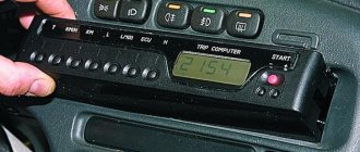
After all the actions taken, the connection of the tachometer remains. In this case, a loop antenna and a reading device are combined. Connector X3 has a gray-black outgoing wire. It is connected to the tachometer as shown in the VAZ dashboard diagram:
This will allow the alarm to control the speed. And at the very end we connect the ground from the main unit. This is a black cord from connector X3.
What are they used for?
Structurally, the shock sensor is a small compact device. In most cases, the sensor is almost invisible. Install it on areas of the machine that are most likely to be subject to shock.
When a shock or sudden movement occurs, the sensor is triggered, activates the alarm, and sends a warning signal to the car owner via the control panel or directly to a smartphone.
The sensor will respond to any movements that cause the surface where the device is attached to vibrate. The reaction occurs in a matter of moments, and the driver receives the appropriate information.
The main task of the sensor is to prevent crime, among which it is worth highlighting car theft, hijacking, damage to property, unauthorized entry into the vehicle, etc.
Settings
Only autorun functions can be configured. To activate programming mode:
- Disable security
- The ignition key is set to position 0.
- Then press the Valet key six times in the main block.
- Turn on the ignition
- After six beeps, use the same key to select the desired function, and use the key on the key fob to select the desired value.
The optimal settings for VAZ - 2115.2114 will be the following: function 12 - set to value 3, function 11 - value 4, function 9 - value 3. To select value 4, press and hold the third button until the melody is played. After playing, press it again.
To check the correct connections, perform the following steps:
- Disconnect the yellow cord from block A91 to terminal 15 for a while.
- The engine is started using the ignition key
At the same time, the alarm indicator should blink.
Remote engine start
Available in the following options:
- At a distance by command from the remote control;
- Periodically according to the timer settings;
- By alarm setting time;
- According to ambient temperature.
What steps are taken to set up software neutral?
· The parking brake system is activated. The engine is running.
· The driver leaves the place, closing the doors. The motor continues to run
· By pressing button No. 1, the car is armed.
· The motor is ready for remote start.
Table: starting, extending operation and stopping the engine from the key fob
| Manipulation | Information from the machine | Information from the key fob |
| Start the engine from a distance | ||
| Key No. 1 for a long time, then key No. 3 briefly |
|
|
| Extending the operating period of the motor | ||
| Key No. 1 for a long time, then key No. 3 briefly |
| |
| Stopping the engine from a distance | ||
| Long press key No. 2, then click on No. 3 | Optics gives four flashes |
Table: instructions for setting autorun by time
| Manipulation | Information from the machine | Information from the key fob |
| Setting a timed start | ||
| Long press of button No. 3 | LED flashes in blocks of three | The keychain makes sounds - long and short |
| Button 3 on the remote control is released | — | Icons flickering in the display control bar |
|
|
|
| Disabling start by time | ||
| Two optical flashes |
|
Table: temperature trigger setting
| Manipulation | Information from the machine | Information from the key fob |
| Activation of autostart by temperature | ||
| Key held #3 | The LED blinks in blocks of three flashes | Alerts are sent to the key fob - long and short sound |
| The key is released | — | Flashes on the display |
|
| |
| Shutdown | ||
| Two optical flashes |
|
Table: autostart on alarm clock
| Manipulation | Information from the machine | Information from the key fob |
| Activating autorun by setting an alarm | ||
| Button #3 is held down | The LED blinks in blocks of two flashes | Alerts are sent to the key fob - long and short sound |
| The key is released | — | Blinking on the screen |
|
| |
| Shutdown | ||
| The optics will blink twice. |
|
Central locking diagram for VAZ 2114
To connect a car alarm to the central locking on a VAZ 2114, you need to know the circuit diagram of the central locking system itself. This will allow you to understand what should be connected to what. Below is a standard lock diagram.
The control module is located under the vehicle's dashboard on the left side. There are six wires in its connector. If the white wire is connected to terminal 7, then it is responsible for unlocking the doors. But in some vehicles, terminals 5 and 7 may not be used. In this case, this function is performed by the brown wire connected to terminal 8. Terminals 5 and 6 are always responsible for locking. When planning to install the alarm, you need to make sure that the driver’s door contains exactly the 5-wire actuator, typical for this VAZ model. Some cars may have a toggle switch instead. In this case, you will need to install an actuator.
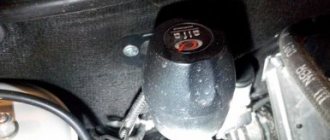
Central locking actuator
It is difficult to do this with your own hands without knowledge of auto electrics. Therefore, if they are absent, it is better to contact a car service.
Alarm connection points for VAZ 2114
Most modern alarms can be connected to the door, hood and trunk switches.
Therefore, in order to connect the signaling system to the VAZ 2114, you need to observe the following points:
- Connector X3 with a blue-red wire to the car door sensors;
- X9 – to a two-level shock sensor, which is attached to a metal surface;
- X8 and X7 – usually not used;
- X6 – to the Valet service button, which is placed in a place hidden from prying eyes in the car;
- X5 – LED alarm indicator, which is located on the dashboard;
- X4 – to the transmitting sensor receiving module. It is installed on the windshield in one of the upper corners;
- X3 – connector with a large number of wires.
To connect the car alarm to all car systems, you need to connect the wires in this order:
- Red – to the “plus” of the ignition switch;
- Black/green and green/yellow – to direction indicators and sidelights;
- Black – for vehicle weight;
- Yellow – to the ignition switch;
- Gray – positive emergency siren;
- Blue/red – “plus” door entrance;
- Black/red – additional blocking relay;
- Orange/gray – to the hood opening sensor;
- Orange/white – trunk opening sensor;
- Orange/purple – to the brakes, according to the diagram presented in the instructions for the security device. It may differ for signaling devices from different companies;
- X2 – to door opening activators;
- X1 – to the ignition switch. It should be connected to the red wire.
How to connect
Installation of the VAZ-2114 alarm system begins with disconnecting the battery and determining the location of the elements. The control unit is placed under the instrument panel or behind the glove box, the siren is placed in the engine compartment. Guided by the instructions and diagram, all elements are connected.
The control unit is connected through connectors to system elements, components and vehicle parts. Installation and installation begin from the farthest point of installation of the security system element, using 9 connectors (X) for connection.
Sensors (limit switches) are installed in the engine compartment, under the hood and in the trunk, which react to opening. The door trims are dismantled to install activators. The Valet service button is installed in a place hidden from prying eyes, but easily accessible to the car owner.
A transmit-receive antenna is installed on the windshield in the upper corner. It is recommended to install the shock sensor inside the passenger compartment, securing it to a metal surface. The emergency siren is installed in the engine compartment with the bell facing down.
When all the elements are located in their places, you can begin to connect them into a single system.
The characteristics of the Starline A 91 car alarm and the connection diagram of the main elements are given in the manufacturer's instructions. When connecting a 6-pin connector X 2, you may need an additional door opener activator.
When connecting door opening sensors, use the blue/red wire of connector X 3. All alarm connection points, i.e. connectors (X) look like this:
- X 9 - connect a two-level shock sensor installed on a metal surface.
- X 8 and X 7 - connectors are not used.
- X 6 - Valet service button, installed in a hidden and easily accessible place.
- X 5 - LED indicator, installed on the instrument panel.
- X 4 - transmitting sensor receiving module; it is recommended to install it in one of the upper corners of the windshield.
- X 3 - connector with many wires.
They are connected to the systems with wires of the following colors:
In basic configurations, the control unit (CU) of the central locking (CL) performs the function of locking the door lock. The electrical circuit connection diagram is the same for all central locks, the only difference may be in the control unit, activators and the number of pins for connecting an additional device.
The main elements of the central lock include the control unit, door sensor switches (limit switches) and microswitches that fix the position of the key. All these elements are connected to the alarm and interior lighting of the car.
To connect to the central locking, it is necessary to connect the central locking control unit (CU) to the car alarm using the door opening and closing relay, to the car ignition switch and to the door opening sensors. When installing the central locking, you will need additional parts, such as:
- diode 1A - 3 pcs.;
- 3A diode - 1 pc.;
- diode 5A - 2 pcs.
In order to insert into the wires, you first need to free them from under the threshold trim. To do this, unscrew the fastening screws and remove the upholstery. Underneath there are 2 wire harnesses running to the instrument panel. One of the harnesses contains the parking brake wire. 2 wires are connected to the sidelights and side indicators.
When inserting into the parking brake wire, 1 diode is installed, and 2 diodes are installed in the wire that powers the side headlights and side turn indicators. The terminals of the insertion wires are connected to connector X 3 of the alarm control unit.
One of the functions of the Starlin car alarm system is auto engine start. In order to install with autostart yourself, you need to use the ignition switch wires. The lilac wire is connected to the battery. Blue (ignition switch) is connected to the alarm control unit via connector X 1.
Connecting to wires
Connection to the “four” wires must be carried out in the order indicated above. In this case, you must follow the instructions in the instructions for the alarm. But first you need to place all the alarm elements in the car. Before starting work, turn off the battery power. The device control unit is placed under the dashboard. The siren must be located in the engine compartment. An emergency siren should also be installed there. In the trunk, under the hood, and also in the engine compartment, you need to install limit switches for opening. Place the Valet button in a place hidden from prying eyes. Attach the antenna of the security device to the windshield in the upper right or left corner. Place the shock sensor on a metal surface. Next, the car alarm is connected according to the diagram. To connect it to the central locking you need to purchase the following items:
- 2-3 pieces of 1N4001 diodes for a current of no more than one Ampere;
- One 1N5401 3 Ampere diode;
- Also, some security systems may require two 4-5 Ampere power diodes.
To connect the device to the central locking system, you need to find two wire harnesses on the floor next to the driver's door. To get them, you need to remove the sill trim and side panel. The first harness contains the door switch cable. A 1N5401 diode must be installed in its gap.
In the second harness you need to find the wire going to the handbrake, into which you should insert the second 1N4001 diode.
The blue cords of both harnesses must be connected to the car alarm.
Required materials and tools
Before starting work, you must stock up on the following materials:
- plastic clamps for attaching the unit, sensors and wires;
- high-quality electrical tape;
- Double-sided tape;
- self-tapping screws;
- 4 diodes (if they are not included in the alarm package);
- foam;
- a roll of insulated wire.
The wire cross-section should be within 0.5-1 mm2. For perfectionists, you can prepare black electrical tape so that it does not differ from that used in standard wiring.
To install the elements and configure the connection, the following tools are required:
- multimeter for checking voltage, contact and short circuits;
- a slotted and Phillips screwdriver (on some machines you will also need an asterisk);
- plastic or rubber tube (cambric);
- socket wrenches (sometimes just a 10mm socket is enough);
- knife;
- wire cutters;
- a device for dismantling plastic door trim (you can get by with a large flat-head screwdriver).
In addition to the above, you may need a drill and self-tapping screws for attaching the sensors and siren.
Connecting autorun
If the alarm has an autostart function, it can be implemented on the “fourteenth”. The ignition switch of this car is equipped with three terminals:
- 15 – blue wire;
- 30 – lilac cable;
- 50 – red wire.
To connect the alarm you will need a 30 connector. The cable coming from terminal X1 should be connected to pin 15. The gray-black wire from connector X3 must be connected to the tachometer. This way the alarm will be able to read the revolutions. The black cable of terminal X1 is connected to ground. The red wire from the ignition switch needs to be broken. You should also cut the loop responsible for selecting the transmission, since the car is equipped with a manual transmission.
After the work has been done, you should configure the autostart according to the instructions for the car alarm.
Functions
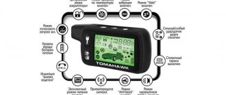
Starline twage a91 is rich in functionality. The functions built into the system are performed both automatically and by pressing the key fob buttons.
Keychain Starline A91
Car security
Like other alarm systems, “Starline” turns on an alarm when the sensors are triggered and reports this to the key fob with an LCD display. Protected areas and what they are controlled by can be distributed as follows:
- The hood, trunk, doors and brakes have limit switches.
- Body - shock sensor.
- Salon - optional with an additional sensor.
- Ignition - ignition circuit control input.
- Engine - with a regular relay.
The alarm is equipped with an anti-burglary function, which can be switched to hidden mode. If you press the buttons on the key fob during the theft, the car will stall and the siren will sound. Additionally, there is an immobilizer mode that turns off the car if there are no keys in the ignition for more than 30 seconds, and a turbo timer that allows the engine to run for a while after the ignition is turned off.
The engine locks are programmed in 2 steps, and for emergency shutdown of the alarm there is a code that you also set yourself.
Remote control
The car alarm has a remote engine start and stop function with wide settings:
- choice of engine type;
- choice of transmission type;
- prolonging the operation of a running engine;
- starter over-twist protection;
- automatic start by timer, alarm clock and temperature;
Security directly alarm
Starline a91 dialog protects not only the car, but also its system from hacking. Thus, the dialog code, the keys to which you specify yourself, prevents the system from being hacked. When the power is turned off, all settings are saved, eliminating the need for reconfiguration.
LED notification
The signaling system lets you know about possible malfunctions using LED indication. The display reports:
- faulty security sensors;
- the state of the alarm system in general;
- reasons and zone of alarm activation;
- faulty zone (only if the security mode is turned on);
- serviceability of limit switches;
LED on car panel
Alarm service functions
The service functions of “Dialogue” include more than 25 settings and modes, the most important of the latter being the following modes:
- quiet operation;
- protection with the engine running;
- silent activation and disabling of the security mode;
- search for a car;
- panic;
- official;
- calling a car;
Others, such as blocking from accidental pressing of key fob buttons and car lighting control, help set up the alarm system as flexibly and conveniently as possible for each user.
Car alarm connection points for VAZ 2114 2008 - 2010
ChainColorPolarityLocation+ 12VPinkPositiveIgnition switchStarterRedIgnitionBlue/blackDriver's doorBlue/whiteNegativeIndication unitRemaining doorsGray/blackTrunkInstall limit switch. (But it’s not possible to install it there! I didn’t install it...) Central locking * Blue and brown Negative Harness from the central locking unit (top left, above the clutch pedal) Turns Blue and blue/black Positive Harness, on the left of the clutch pedal, under the mat or on the emergency brake button Handbrake Brown/blue Negative Noodles- harness, left clutch pedal, under the mat Engine operation can be monitored using any of the signals:Tachometer Brown/red Instrument panel. Connect through a non-polar capacitor 2 µFChargingBrown/WhitePositiveInstrument Panel*You may need to install a 5-wire electric. lock on the driver's door. Connect the lock to the central locking unit to the thick Red and Yellow wires. It is possible that cr. and yellow. The wires are already installed in the driver's door, you can connect the lock to them. If not, you will have to throw it into the cabin and connect it to the central locking unit, to the same yellow one. and cr. wires. The limit switch, which is inside the el. lock, connect it to the place of the standard limit switch, which is on the lock, in the door. The wires are black (ground), blue, brown (open/closed).Sources
- autosiga.ru/elektroprovodka/vaz/910-ustanovka-avtosignalizatsii-na-vaz-2114-tochki-podklyucheniya-raspolozhenie-i-tsveta-provodov
- vaz-2114.info/podklyuchenie-signalizaczii-k-czentralnomu-zamku-na-vaz-2114/
- alarmspec.ru/signalizacii/ustanovka-signalizacij/ustanovka-signalizacii-na-vaz-2114-i-na-vaz-2115.html
- drive2.ru/b/470688834296742970/