The problem of how to connect an alarm system to the central locking of a domestic car has been relevant for VAZ owners since 2000. Before this, central locks were not installed at all on Tolyatti models. Now the useful device is offered for basic configurations as an additional option. Realizing the benefits of central locking and car security alarms, many car owners install both devices on domestic cars of all years, especially since self-installation helps save money. VAZ models make up about half of the country's car fleet, and ensuring their safety is of interest to millions of drivers.
Lada Priora Sedan “S line” › Logbook › DIY installation of Starline A91
The other day I installed a STARLINE A91 alarm system on my car. It took me two days, 6 hours each, to install it. But I still spent a lot of this time on debriefing - what, where and how to connect. I read a lot of blogs and decided to write short instructions for installing such an alarm. Let me clarify right away that I did not connect the trunk opening button and the engine blocking relay to the alarm, and I also did not do step-by-step opening of the doors. Let me jump ahead - only four wires need to be cut completely (to the central locking in the door, to the starter, to the standard immobilizer bypass and to the handbrake), we simply connect the rest in parallel.
PS I didn’t take any photos during installation because... I didn't see the point in this.
To begin with, I purchased: 1) corrugated cables. It took me about 6 meters, because... I hid all the wires in it. (the length depends on where you will have the alarm unit)2) electrical tape3) 4 1N4007 diodes (if not included with the alarm)4) wire. (also depends on where the signaling is installed, because the length of some wires is not enough) 5) a standard immobilizer crawler (in which we put the chip) 6) a lot of patience. After all, you’ll have to crawl on your knees under the steering wheel and there’s not too much space there))))
Now briefly about the installation: 1) remove the fuse box cover
5) unscrew the BUS with a 10mm wrench. It is held on by two bolts. I only needed to unscrew one side and I pulled it out.
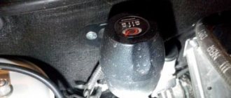
6) we put the antenna on the windshield 7) I embedded the light bulb into the trim of the left pillar
The shock sensor is written that it needs to be placed on the body and so that there is access to it for adjustment, but I did not find such a place and placed it to the right of the fuse block on plastic. 9) we hide the service button somewhere but so that you can reach it while configuring the alarm .10) from the engine compartment we pull three wires from the signaling system from the 18-pin connector - orange-gray, black, grey. Gray is the plus for the siren, we connect the minus from the siren to the body. Orange-gray and black we connect to the temperature sensor that comes complete with signaling I bolted the temperature sensor to the engine. We also additionally connect the orange-gray wire to the hood end switch (to the white-black wire) 11) and from the 18-pin connector we pull two wires into the instrument panel - gray-black, orange-violet. Gray - we connect black to brown-white (this is a generator), and orange-violet to brown-blue (this is a handbrake) according to the diagram. (The diode must be connected exactly according to the diagram. The diode designations are present in the picture)
PS later redid the control of engine operation using the tachometer because there were problems with reading the generator. In general, the gray-black signal wire should be connected to the brown-red one in the instrument panel and in the signaling settings, control the engine operation using the tachometer.
12) We cut the loop of black wire from the 18-pin connector if you have a manual transmission 13) We lay two wires from the 6-pin connector of the central locking alarm into the driver's door - green and green-black. connect it to the brown wire near the central locking unit. make connections according to the diagram below
Also note that the blue wire needs to be connected to the green one, and the black and red wire must be cut and one end (which goes to the unlocking relay) connected to the car body
source
Programming the standard control unit
Manufacturers, with each new car leaving the assembly line, increase its comfort and ergonomics. The cars are “stuffed” with electronic safety and comfort systems. They provide maximum driving pleasure.
The car central lock is a convenient and useful invention. Used over the past few decades. Its creation allowed the driver to get rid of unnecessary manipulations associated with opening and closing the driver's and passenger doors.
Since its inception, the central car lock has undergone a number of significant changes. Controls the opening of not only the doors, but also the trunk. The car's central locking cannot operate indefinitely. Sooner or later, malfunctions occur in its operation requiring repair or complete replacement of the system.
A person who gets used to good things is sensitive to the failure of comfort systems. He feels uncomfortable wasting time on manipulations that previously required just a finger press. A malfunction of the central locking forces the driver to look for information about why the central locking does not work.
At the end of the article you can find a video on how to repair a car's central locking system. It will be an excellent addition to the text material. Enjoy watching.
Educational program: installing an alarm system on Priora essence
With your own hands, you can install any manufacturer’s security device on the Lada. First you need to carefully study the configuration of the connection of the alarm unit, as well as the electronic circuit of the Priora, in particular, the assignment of the outputs of the electrical package control connector unit 2170 - 3763040, or another. To connect the security module, you will naturally need an operating voltage circuit - 12 volts and a bus body circuit, plus a few more specific circuits:
- ignition switch
- tachometer signal
- end connections of door contactors
- right-left turn signal lights
- trunk end contactors and central
- hood lock
Installation map for Starline A93 Can+Lin car alarm for Lada Priora Lux 2014-15 manual transmission
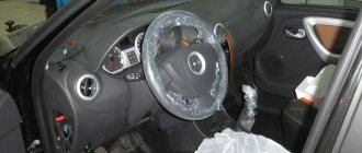
1. To access the ignition switch connector, remove the lower part of the steering shaft housing. To do this, you need to remove the plastic trim under the steering column, releasing the clamps, then remove the lower part of the casing (fastened with three self-tapping screws and two screws).
Steering shaft housing. General form
Plastic lining fasteners
Plastic cover removed
Self-tapping screws and screws for securing the steering shaft housing
The lower part of the steering shaft housing has been removed
2. To access the VSM unit, remove the left side trim of the central tunnel (fastened with one screw). Then remove the VSM unit (mounted with a bolt and nut).
Self-tapping screw for fastening the side trim
Side trim removed
Bolt and nut for fastening the VSM unit
VSM block removed
3. Install the antenna module with built-in shock and tilt sensor on the windshield, LED on the left pillar. Install the service button covertly in any convenient place.
Possible location for installing the antenna module
LED installation location
4. Install the siren under the hood (attach it to the nut) and the engine temperature sensor (using plastic ties). Route the wires into the passenger compartment through the standard seal on the left side of the engine shield.
Possible siren installation location
Siren installed
Engine temperature sensor installation location
The temperature sensor is fixed to the pipe using ties
Standard seal. View from the salon
5. Secure the StarLine A93 central car alarm unit to the right above the BCM unit.
An example of the location of the central car alarm unit
6. Connect the StarLine alarm ground at the bottom left under the VCM unit under the standard nut.
Ground connection
7. Connect the CAN bus and LIN bus StarLine in the harness of connector 3 of the BCM unit.
Conventional numbering of connectors on the VSM unit
CAN bus (yellow-red, pin 16 and gray, pin 15)
LIN bus (blue-white, pin
LIN bus connection
8. Connect the trunk limit switch in the harness of connector 3 of the BCM unit.
Trunk switch (yellow, pin 14)
Connect the hood end switch in the harness of connector 2 of the BCM unit.
Hood switch (white-black, pin 15)
Connecting the hood and trunk limit switch
9. In the harness of connector 2 on the BCM block, connect an alternative control of light signals (black and white wire of connector X3 of the Starline alarm system).
Light signal control (red, pin 5)
10. To bypass the standard immobilizer, remove the battery from the key and place the key in the StarLine BP-03 immobilizer bypass module. Then connect the bypass module to any wire of the standard antenna on the ignition switch.
Standard antenna wires (green and white)
11. In the ignition switch connector harness, connect the engine starting power circuits, power supply to the security system and the autostart power module.
Ignition (blue-black)
Starter (red)
Power + 12V (brown)
12. Program the security and service functions of Starline A93 (see installation instructions, section “Main menu for programming car alarm functions”, Table 1).
13. Program the vehicle starting parameters (see installation instructions, section “Main menu for programming car alarm functions”, table 2).
14. Adjust the sensitivity of the shock and tilt sensor (see the installation instructions, section “Connecting the transceiver (antenna module) and setting the shock and tilt sensor”). Factory sensitivity values: warning level of the shock sensor - 10, alarm level of the shock sensor - 5, tilt and movement sensor - 5. After setting, check the operation of the sensors, if necessary, repeat the setting procedure.
15. Check the operation of the Starline A93 car alarm. Reassemble the interior in the reverse order.
Pinout of the instrument panel VAZ 2170 Priora
The layout of the instrument panel is made in a simplified version to facilitate the replacement and installation of replacement parts. The decoding of the wiring connections at the factory terminals looks like this:
- 1 – EUR;
- 2 – emergency signal control;
- 3 – oil pressure sensor;
- 4 – indicator light for turning on the hand brake;
- 5 – immobilizer control unit;
- 6 – control unit for airbags;
- 7 – external lighting of the car;
- 8-9 – direction indicators;
- 10 – control of the combustible mixture injection system;
- 11 – disabling the front passenger SB;
- 12 – indication of seat belt buckles;
- 13 – operation of the brake system;
- 14 – reset button of the steering column switch;
- 15 – indication of the expansion tank of the brake system;
- 16 – ABS control unit;
- 17 – headlight high beam position switch;
- 18 – dashboard lighting;
- 19 – mass;
- 20 – receiving power from the battery terminal;
- 21 – ignition switch connector;
- 22 – fuel consumption sensor;
- 23-24 – BC mode switch;
- 25-26 – temperature sensor “overboard”;
- 27 – remaining fuel in the tank;
- 28 – speedometer;
- 29 – antifreeze temperature indication;
- 30 – tachometer;
- 31 – diagnostic terminal;
- 32 – power supply from generator (L).
Alarm activation
In order to activate the standard alarm, you will need a training and master key, which must be issued upon purchase of the car.
Be sure to pay attention to this, or in the future you will have to contact the dealer separately. You will need to carry out the following actions in the prescribed manner:
- Fill the fuel tank (at least 10 l). This action must be performed so as not to get confused in the signals supplied by the immobilizer and to carry out the sequence of operations in strict accordance with the algorithm.
- First of all, you need to use the learning key, which is inserted into the ignition switch. The ignition must be turned on for a certain time (about 6 seconds), and all doors in the car must be tightly closed. Correct actions can be monitored by a rapidly flashing (about 5 times per second) indicator lamp. After this, you can turn off the ignition and remove the learning key from the lock.
Important points for connecting the immobilizer
- Immediately after removing the training key, you need to quickly (until the warning light goes out) insert the main working key and turn on the ignition again. Three signals will confirm the correctness of your actions. But you need to wait for the next two signals after a certain time, after which you can turn off the ignition and remove the key.
- The key must remain in the lock. Confirmation of the correctness of the actions will be another, this time a single signal with a rapid blinking of the immobilizer warning lamp.
- Now the ignition is turned on briefly (for 2-3 seconds), and after turning it off, you need to wait for the sound signal to sound three times, and the warning lamp stops blinking. Before starting the engine, you need to take a long pause (at least 10 seconds).
Lada Priora: We will reprogram the standard alarm system
Some tricks of the Lada Priora
(Granta, Kalina, etc.). 1) Turn on the heated mirrors 2) Reprogram.
Disabling any alarm
Here's a simple way to turn it off
almost any
alarm
.
At this point, immobilizer training can be considered complete. The alarm installation for the Priora may not be done correctly, or another malfunction of the security system may occur as a result of which the car engine will not be able to start. Such a failure can be monitored as follows:
- We turn on the ignition with the working key and after a while (usually 5-6 seconds) we visually check the warning lamp. If it blinks once per second, this mode indicates an error condition. It is enough to turn on the ignition again after 10-15 seconds for the device to resynchronize.
- If the error is detected again and in a situation where the light is constantly on, the entire procedure for learning the standard alarm is carried out again.
Keep the special training key, as it may be required if it is necessary to retrain the immobilizer, or if a copy of the key is made. Cases when you have to make and use a new working key are not that rare. The technical capabilities of the protective device can be significantly expanded in practice. Often, Priora owners take advantage of additional features such as:
- delay in turning off the interior lamp;
- remote activation of the rear fog lamp;
- a “forgetful” driver signal that will remind you if the driver left the key in the lock when leaving the car;
- Reminder that external lights are not turned off.
Wiring check
Instructions for cars of the B0 assembly line (XRAY, Largus, Nissan Almera, Renault Duster, Sandero). Remove the limit switch and set the multimeter to voltmeter mode. We measure the voltage at the contacts of the block with the wires:
- If there is no voltage, the circuit of the interior lamp lamp or the lamp itself is faulty.
- if the voltage is significantly less than 12 V, the wire connecting the sensor to ground is probably damaged.
We set the multimeter to ohmmeter mode, connect one probe to ground (body), and the other to the terminal of the block with the black wire. The resistance should be close to zero. If the resistance is high and tends to infinity, the connection between the wire and the body is probably damaged by corrosion or the wire is damaged (treat the connection with a product to protect electrical contacts). If the fault cannot be resolved in this way, it is necessary to remove the interior trim from the pillar, find and fix the fault.
Algorithm of actions
- Make sure there are no signs of damage to the key fob. Check the functionality of buttons and contacts.
- Check the power supply. If necessary, replace with a new one.
- Check the functionality of the central control unit. If the central unit breaks down or malfunctions, you will need to contact the service center installers to install new software.
- The device that detects impacts on the surface of the car may not work if the settings are incorrect.
- Drivers often encounter the opposite problem - the system reacts to the slightest contact with the body as a result of falling leaves, wind, rain, snow, etc. You will also need help with setup here.
Another common problem that the driver cannot cope with on his own is the loss of connection between the power supply and the electromagnetic contact. The contact ensures uninterrupted opening and closing of the prior doors. To determine the problem, you need a special device - a multimeter. Depending on the reasons that caused the malfunction, reinstallation of the software or replacement of parts is required.
Possible faults
Installing a factory alarm does not lead to the frequent need to disable the standard alarm system on the Priora. This is due to minimal functionality and the prevention of malfunctions in the event of unqualified installation of this unit on a car.
However, breakdowns can still occur, as with any electronic and electrical devices on a modern car. Among the most common types of malfunctions, in the case of using an alarm system in conjunction with an immobilizer, the following items can be distinguished:
- inability to start the engine;
- lack of response from the control unit to the key fob signal;
- failure of the body impact sensor;
- frequent alarm activation for no apparent reason;
- blocking doors after receiving a command to open.
One of the typical malfunctions of the standard device itself lies in its very design. Here, the security action underlies the blocking of the ignition system. Therefore, it is not uncommon that after 2-3 years of active use, during the next attempt to start, the starter either does not respond to turning the key, or its operation stops after a few turns.
In such a situation, the very first action will be to temporarily disable the protective device with later diagnostics. If incorrect operation of the alarm control key fob is detected, its condition must be monitored in the following sequence:
- Monitoring the operation of buttons and the state of contacts. Inspect the key fob body for external damage.
- Monitoring the state of the battery. If necessary, replace it.
- Monitoring the health of the control unit. The case of the latter emerging from the influence of external sources is not excluded, although it is an infrequent occurrence. Troubleshooting in this case is the task of the service representative, who will install new software for the control unit.
Failure of the shock sensor to operate may be due to incorrect adjustment (setting). The situation looks similar when the control sensor mistakes a normal gust of wind or too much noise for a blow to the body. In this case, the car owner will not be able to install alarm connection points and control the settings on his own. You will need to contact a service station.
Another malfunction where independent intervention cannot help is the loss of the signal between the power supply and the electromagnetic wire, which is responsible for unlocking and closing the doors. It will be necessary to carry out monitoring with a special multimeter and, if necessary, replace damaged parts or reboot the device.
Alarm characteristics
After modernization, the Lada Priora received a device that plays the role of a basic alarm system and received the traditional name for such devices - an immobilizer. An immobilizer (from the Latin “to immobilize”) is a device that, interacting with an electronic control unit, allows you to block engine operation and prevent unhindered access to the car and its systems.
Moreover, installing the key in the ignition switch socket is not a connecting link, but only allows you to send a signal to the necessary electromagnetic sensor so that the necessary devices carry out their work. Structurally, the immobilizer protective device consists of several blocks that are connected into a single mechanism.
| Name | Location |
| Control block | included in the glass unit control unit |
| communication coil | located in the ignition switch |
| main and training key, which are equipped with contact buttons and a buzzer | |
| control button | on the control panel |
When operating a car, a standard alarm system will require the owner to perform several possible actions:
- immobilizer activation and training;
- car key training;
- use of alarms;
- disabling the immobilizer.
If you are faced with the question of how to activate the immobilizer on a Priora, the first step is to take care of clear instructions (supplied in the kit or in the form of a specialized book) that will help you do this yourself.
Checking the door switch
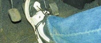
When the rod is recessed, the contacts are open. First of all, we check the serviceability of the sensors by opening all the car doors one by one.
Check with a multimeter. We connect a multimeter to the limit switch terminals in ohmmeter mode and check the closure of the sensor contacts (the contacts must be closed, the resistance is close to zero). We press the sensor rod and check the measurements (the contacts must be open - the resistance tends to infinity).
Let us remind you that in some cases (for example, in the cold season) limit switches may work intermittently. For Lada Vesta, Grant and Kalina 2 you can use this solution, and for Priora this.
Features of connecting the alarm to the lock on the driver's door
Installing a central lock on the driver's door allows the owner to avoid the main reason for car theft: opening one of the passenger doors. That is why you should carefully study the car alarm connection points on the Priora in order to ensure maximum protection and ease of use of the vehicle.
For the central locking to function, you will need to connect two wires to the driver's door. They should be triggered by a break in the brown wire when the lock is closed and, accordingly, the locking buttons are activated.
For the modern Lada Priora, the alarm connection points responsible for the normal operation of the autostart are also very important. You will need to connect a brown wire with a red streak to the dashboard connector. And the brown/white wire is connected to the generator. All this allows you to control the autostart procedure. The last connection point will be the brown/blue wire from the handbrake.
Upon completion of the full procedure for searching for points and connecting the corresponding wires to them, you need to visually evaluate the connections and check the operation of the alarm in action. Until the moment of complete reliability in the correct functioning, the Lada Priora alarm connection points must remain open.
This will allow you to immediately begin correcting them if any problems are detected. Once the goal is achieved, the plastic of the front panel and tunnels can be replaced.
StarLine A91 Dialog is a modern car security system with a radio control dialogue code “Quick Dialog” and an engine auto-start function. Thus, “Quick Dialogue” is considered a control code with individual encryption keys, which excludes intelligent electronic hacking.
Resistant to all code grabbers. In order to protect the code, we apply the dialog code algorithm perfected at this stage. Complemented by the innovative frequency hopping method. In this method, when transmitting commands, the patented OEM transceiver changes frequencies many times according to a special program during the period of each transmission.
ATTENTION! A completely simple way to reduce fuel consumption has been found! Don't believe me? An auto mechanic with 15 years of experience also didn’t believe it until he tried it. And now he saves 35,000 rubles a year on gasoline! Read more". A solution of this level, which is a method of expanding the spectrum with frequency hopping, is used for the first time in an alarm control system and is a significant complication of all kinds of attempts to crack the code
A solution of this level, which is a method of spreading the spectrum with frequency hopping, is being used for the first time in an alarm control system and is a significant complication of all kinds of attempts to crack the code.
What is a car alarm
The possibility of increased control and warning range, as well as reliable operation in extreme urban radio interference, is ensured by the use of a 128-channel patented transceiver with FM modulation and a narrow bandwidth.
Thanks to a specialized signal processing program, narrow-band filters, as well as reception and transmission channels optimally distributed along the edges of the 433.92 MHz frequency range, it became possible to improve the signal-to-noise ratio by 8-10 dB and double the range and noise immunity.
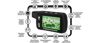
Remote starting and control of the operation of various types of engines is provided by a specialized processor. The existing key fobs implement an intuitive control principle. The pictograms on the keychain are presented in Russian.
The StarLine A91 Dialog car alarm can be installed on various cars with gasoline, diesel or turbocharged engines, with an automatic or manual transmission.
Thanks to more than 60 standard, programmable functions, not only reliable protection is provided, but also comfort when using a car alarm such as StarLine A91 Dialog.
Why are there no friends
Even the most shy and unsociable introvert needs a friend. At least in one. A best friend is a person who knows you well, is always ready to help, and is fun and cool to spend time with.
The older a person gets, the fewer real friends he has. After all, often the strongest friendships we have are with those whom we met in childhood, grew up and matured together. And then different situations happen in life when we find ourselves alone without our usual social circle:
- moving to another city or country;
- loss of contact with old friends due to the fact that you have families and do not have enough time to communicate;
- you just want to change your current environment because you have outgrown the level of your friends;
- your “other half” categorically does not like your friends or girlfriends.
This is not an exhaustive list, but whatever the reason for your loneliness, you can always meet new people who can become friends.
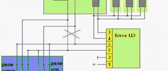
Two schemes (simple and complex)
First of all, before connecting the alarm, you need to study the instructions included with it. The main unit always has relays installed: one of them closes when the locks are locked, the second acts on opening. The connector to which the relay contacts are connected usually has 6 pins. There is nothing complicated here.
In the first case, we will use only this connector. The second circuit uses another contact, called “signal output for 2-step lock opening”. Find it on the main unit.
We connect the alarm in a simple way
A push-button module is installed in the driver's door of the Lada Priora. The door trim must be removed and the connector for this module must be found:
We will need a brown cord from the connector. It is a signal, and the alarm relay is connected to its break:
Two wires connected to each side of the cut cord will have to be pulled to the main unit. The common contacts of the relay are connected to one of the wires.
All wiring in the considered circuit is signal, but this does not mean that the connection points need not be isolated. Wires should not touch metal parts of the car. If contact occurs, it is necessary to use additional protection: electrical tape, heat-resistant tube, etc.
The best option for connecting to the central locking system
Having made the connection, as discussed above, you can notice the following: all locks are activated from the key fob for closing, and only one, the driver’s, is activated for unlocking. This defect can be eliminated 100%, which will require 2 or 3 additional relays. First, let's look at where the connection points are:
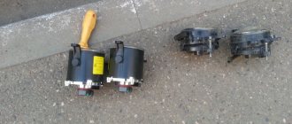
The block that is visible in the photo is designated BUS-2170. It is equipped with three connectors, but we need one (three-row).
Find three wires in connector X1:
- Sixth (red-black). The cord goes to the actuators and is the power one.
- Thirteenth (green-black). Front right power window control cable.
- Eleventh. Same as “13”, but for the rear window lifter.
How to connect an alarm system to the central locking of a Priora Lux? Three wires are broken (all indicated), and the cables from the break points are pulled to the signaling unit. If you don't have rear power windows, the last cord will be missing. And if there are no power windows at all, cables 3 and 2 do not break (they are still missing).
The BUS unit will be installed behind the dashboard, near the gas pedal. To remove it, dismantle the side panels and unscrew two 10mm nuts. These nuts secure the block on both sides. From each of the break points, a cable is laid to the signaling system, which also applies to the brown cord coming from the door block:
Here we use additional relays (K1-K3), a 15 Ampere fuse and nothing more.
Installation of limiters from Ford Focus 3
To work you will need the following tools:
- Collar;
- Torx bit T20;
- Torx bit T40;
- A plastic spatula for dismantling upholstery components - if you don’t have one, you can use a thin screwdriver, first placing a cloth under it so as not to damage the door card components and paintwork.
- Head for 10.
First you need to remove the door cards. First, use a plastic spatula to remove all components that block access to the bolts. You need to work carefully so as not to break the latches. Next, the mounting bolts are unscrewed using a T20 Torx bit. That's all - all that remains is to snap off the card, which is secured along the contour with caps
At the same time, it is important not to break the door opening handle, and also to disconnect the plugs for the electric windows. Then you need to remove the insulating material glued to the door to gain access inside
The next step is to dismantle the limiter itself. It is screwed to the body with one Torx T40 bolt, and to the door with a pair of bolts, to unscrew which you will need a 10mm socket. When the bolts are unscrewed, all that remains is to remove the limiter, but this must be done carefully, since you can lose the washers on the studs (in the places where the element is attached to door). In addition, after removing the limiter from the Vesta door, you need to make sure that the door does not open further than it should, which is especially important for the front doors. Otherwise, you can crush the edge and damage the paintwork.
The process of removing the upholstery and the door stop itself from the Lada Vesta is clearly demonstrated in the video
Installing limiters from Focus 3 in Vesta is not difficult, but there is one point. During installation, those 2 mm differences between the studs that were mentioned earlier begin to affect. For this reason, the limiter is not installed. There are two ways to solve the problem:
- Working with holes - you need to carefully drill out the seats with a drill or bore them with a file so that the element becomes as needed.
- Adjusting the studs - it involves bending the studs slightly inward so that they fit freely into the holes.
As practice shows, it is still better to squander the seats. Yes, it takes longer, but it is much more reliable. The reason is that the pins on the limiter are hardened, so if you bend them more than necessary, they can break and the limiter will have to be thrown away. In addition, before installation you need to put thick washers or nuts on the studs themselves. This is necessary, since the length of the element pins from Focus is several millimeters longer than those on Vesta.
If this is not done, the functionality of the component will not be affected, but at the end of the stroke it will no longer be a spare part from Ford that will stop the doors, but a factory additional stop. As a result, the paint will peel off very quickly and corrosion will appear at the contact point.
Once the stops are installed, you can reassemble the doors in reverse order.
Notes on implementation of schemes
Let us immediately note: if there are no window lifters, the second diagram will not contain parts K2/K3. Then you only need to cut one wire. Sometimes only the rear windows are missing. This means that relay K3 is excluded. And the diodes connected in parallel with the winding can be absolutely anything.
Diode, zener diode - everything will do
Now we list the requirements for an element called “relay”:
- Operation voltage – 12 Volts;
- Switching current – 10 A or higher;
- The current consumed by all relay windings should not exceed the value specified in the instructions for the signaling. Usually it is 200-300 mA.
Diode with relay, ready module
In order for “scheme 2” to work, it is necessary not only to assemble it, but also to program the main unit: you need to enable the “2-step unlocking” option. And be that as it may, control impulses cannot be made too long. Use values of 0.7-1.1 seconds.
Power cables (cord X1-6) can only be connected using twists.
The cross-sectional area of the wire must be sufficient to withstand a current of “10 Amps” (this does not apply to signal circuits). A fuse protecting the power circuits must be installed. And of course, before installation, remove the negative terminal of the battery.
Central locking circuits
Locking and unlocking of the interior doors is organized through a two-step central locking chain. Three contacts of the electrical package control unit are connected to this circuit through a relay system. One power contact (12 V) and two contacts from which the control signal for the power window drives (front and rear) is removed. The two-step central locking circuit is connected through relay coils to the alarm module, and the door lock signals are removed from the alarm module.
Completion of educational program about Lada Priora
After reading, many will probably be overcome by a feeling of powerlessness. Indeed, all the described actions cannot be completed if you do not have experience in repairing Russian Zhiguli cars, as well as the skills of a specialist in electronic systems. The bulk of car owners are still ordinary people who use the vehicle simply as a household appliance and nothing more.
All thoughts are more likely to suit creative people - those who not only drive a Zhiguli, but always strive to improve. For this category of readers, all that remains is to add: all the necessary diagrams of connectors, connections, wiring are available in sufficient quantities on the network. So, you can pick up the tool and start installing the latest model of alarm system on the Priora, if one has not yet been installed to this day.
Security systems with feedback
These are much more complex alarms. Many of these systems are controlled via satellite communications. In addition to the functions listed for one-way signals, there are, as a rule, many more additions, for example, autostart. When the car can be started to warm up without leaving home. And the display of the key fob displays information about the state of the car, open and closed doors, temperature and engine speed.
Also, this system is able to establish the location of the vehicle via GPS satellite.
For M-73 the process will look simpler:
Installing the OpenBox program and the HxD file editor on your computer. Connecting the immobilizer to the computer via an adapter, the standard EEPROM code is read. The code is saved. Open the saved code in a file editor and add the first line with the text: FFFFFFFFFF. Save changes. But such a file can be searched on the Internet. Load the edited code into the immo memory through the program. Disconnect the module and install it in the car. Disabling the immobilizer using a crawler
It is easier to disable the immobilizer on a Priora yourself using a device - an immobilizer crawler for a Priora (most often they are produced by Starline). To do this you need:
Find and disassemble the immobilizer unit in the Priora. Before disconnecting from the network, connect to the computer via an adapter. Resolder the resistor chip to modify the blocker control module. Run Eeprom and Flash diagnostics, save existing versions. Install the “untrained” program in place of the old one. Solder the resistor chip. Deactivate the anti-theft system. To do this, you can change the ignition switch in the Priora to “update” the immobilizer. It’s just that the immobilizer training key will not be used in the future. Disabling the immobilizer without using a crawler
These methods have already been described and they are more reliable because they completely change the firmware of the device and provide a guarantee that the immobilizer will no longer break and will not leave the car owner in the cold. Using a waste module may be an innovative way, but it only masks the problem, not eradicates it.
The standard alarm system on the Lada Priora consists of the following links:
- Control unit – connected to the glass unit control system;
- Communication coil – installed in the ignition switch;
- Main and demonstrative keys, which are equipped with a buzzer and contact keys;
- Central key on the dashboard;
- The control unit is located on the right side of the brake pedal. It has several connection points.
Key programming for Kalina, Priora, Grants, UAZ and Niva
The remote control key for Lada Priora, Kalina, Granta, UAZ Patriot, Niva is programmed on the car without any devices.
To do this, you need to have a so-called training key in your hands - which has a red pip on the head of the key. Used in cars with APS-6 unit. The remote control key looks like this:
IMPORTANT ANNOUNCEMENT. We work and consult ONLY in Nizhny Novgorod
If you are from another region, do not write or call us - we will not answer. We do not treat keys or cars from other cities: contact specialists in your region
We work and consult ONLY in Nizhny Novgorod. If you are from another region, do not write or call us - we will not answer. We do not treat keys or cars from other cities: contact specialists in your region.
How to disable the immobilizer
It is difficult to disable immo on your own, because it is activated at the car dealership upon purchase, or at a car service center only if the owner of the car expresses his desire. Disabling the immobilizer on a Priora means reprogramming the electronic immo control unit. But not everything is so simple - an adapter and software are needed to change the code, because the immobilizer operating algorithm is written in a programming language that is not basic for computer operating systems. Remember that you can disable the immobilizer only when you are sure that the car is safe.
The procedure for disabling the immobilizer may vary. It all depends on the generation of the device board - either M73 or M74 was installed in the immobilizer. Anyone who is looking for how to independently disable the immobilizer on a Priora should find a K-Line class adapter.