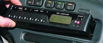
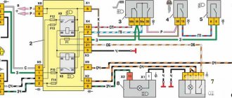
Hi all! I have long wanted to try to install an alarm on our car, and I succeeded and so I’m telling you how I did it. To connect the alarm, I drew an approximate diagram (based on the Starline A91 diagram) (Since I don’t have an immobilizer on my car, I erased it from the diagram)
Connecting connector x1 Remove the ignition switch from the car for convenience Solder the red alarm wire to the pink wire of the ignition switch (+ alarm) (Or connect to the battery) Solder the yellow wire to the blue wire with a black stripe Cut the red starter wire Solder the black and yellow thin wire to the running wire to the ignition switch Solder the thick black and yellow one to the wire going towards the starter Blue and Green we cut off, we don’t need them
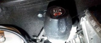
Connecting connector x2 Since from the AvtoVAZ factory, on vases they saved on activators (usually after 2005), there is such a switch
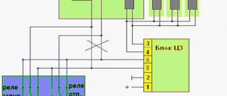
Connecting connector X3 Since we have a manual transmission, we cut the loop (black wire) To the red chip of the dashboard: Turn signals (green-black and green-yellow) are connected to (blue and blue-black)
To connect a temperature sensor, cut off the protection of the orange-gray wire, solder an extension wire (if you don’t need to solder it, solder the sensor like this) for the temperature sensor and solder it to the + of the temperature sensor and connect the minus of the sensor to ground
We connect the blue-black one to the BSK connector (take two wires, pin 7 (passenger door) and pin 13 (driver’s door), cut off the protection from them and solder the blue-black one between these two wires
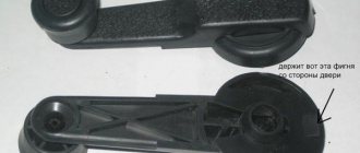
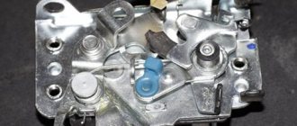
I advise you to replace the limit switches since ours usually turn sour and work poorly, I ordered from Daewoo Nexia Black connected to ground
Next, we will program through the key fob and the valet button the following functions according to table 2 (installation instructions): starter scrolling - 3.6 seconds (form 9 No. 4) tach control (form 11 no. 4) Successful installations!
After purchasing a VAZ-2114 car, the owner is faced with the problem of how to protect his car from unauthorized entry and theft. The most popular method of protection is installing an alarm on the VAZ-2114, which will create difficulties for burglars and notify the owner of the vehicle.
Connecting the central lock
First you need to study in detail the connection diagram for the central locking on a VAZ car - 2115,2114. Finding it is not a problem by searching on the Internet.
The central locking control module is located on the left under the dashboard. Looking there, you will find six wires coming out of the module housing. To install the alarm, you must disconnect the blue and brown cords. As a result, we get a connection corresponding to the following diagram:
Before connecting the alarm, you should make sure that it is not a toggle switch installed on the driver's door, but a standard actuator with five outputs. Otherwise, you will need to install an actuator, which is quite problematic.
On VAZ -2115,2114 cars, the white wire, which is connected to the seventh terminal, is usually responsible for unlocking. If there are no connections at terminals 7 and 5, then the eighth terminal is connected to the brown cord. It is this cord that is responsible for unlocking in this case.
Terminals number five and six are responsible for locking the lock. This arrangement of contacts is typical for almost all blocks of the “ninth” series.
For some reason, none of the instructions for alarms ever indicate that installation requires the purchase of additional elements.
We will definitely need:
- Two to three 1N4001 diodes per Ampere
- One 1N5401 3 Ampere diode
- Two 4 or 5 Ampere diodes if there are no separate outputs for turn signals.
When installing a Starline alarm system, the task is greatly simplified, since significantly fewer additional parts are needed.
Please read carefully!
It is better to choose a heated garage with good access to the interior from the driver’s side and bright lighting as the location for installing the alarm. If such fastening points are not found, you can independently make mass fasteners to the metal body parts of the car under the dashboard.
It turns out that the following connection option is suitable for the Haval brand: in the additional circuit and in the accessory power line, the current should not be interrupted during starter operation. By the way, the hood switch is paralleled with the trunk limit switch. Thus, you can choose the functionality and, accordingly, the cost yourself. Installation of wiring connections according to the connection card must be carried out with the battery disconnected. The author of the video is Auto Electrician Sergey Zaitsev. The Starline A93 security complex provides four ways to control the central lock: low-current control;
Advantages and disadvantages If you study the reviews of owners and specialists about Starline, they will include both positive and negative aspects. Flexible self-diagnosis. Siren 4 is installed in the engine compartment away from the heating elements of the engine. To do this, it is better to perform computer diagnostics. The communicator should emit a melodic signal. Then try turning it off. It is better not to install this element in the engine compartment, since it contains many sensors and electronic devices that will interfere with the digital signal.
Connection diagram
After carefully studying the alarm installation instructions, you can find the following connection diagram:
In this diagram, the designation X2 indicates a six-pin connector. It must be connected according to the diagram above. If you need to install an additional actuator, then it is better to use the diagram given in the instructions.
Now let's figure out how to connect the door sensors. For this purpose, there is a special wire in the connector marked X3.
How to connect
Installation of the VAZ-2114 alarm system begins with disconnecting the battery and determining the location of the elements. The control unit is placed under the instrument panel or behind the glove box, the siren is placed in the engine compartment. Guided by the instructions and diagram, all elements are connected.
The control unit is connected through connectors to system elements, components and vehicle parts. Installation and installation begin from the farthest point of installation of the security system element, using 9 connectors (X) for connection.
Tapping into wires
Next to the driver's door, there are two wire harnesses running right along the floor. One of them has a cable coming from the parking brake and two wires to the turn signals. The second harness contains the door switch cable. This is where you need to start connecting. To do this, remove the sill trim along with the side panel. They are attached using self-tapping screws that must be unscrewed. Having done this, you can see the wiring harness shown in the photo:
This harness goes to the dashboard. We are interested in the door switch cable. If a 1N5401 diode is inserted into the wire break, the current should flow towards the limit switches. And the second diode 1N4001 is connected as shown in the figure.
The following figure shows the second harness:
At the same time, taps are made from the blue cables and the cords are pulled to the place where the alarm will be installed. And the handbrake wire is cut, and a 1N4001 diode is soldered into the cut with the cathode towards the switch.
Connecting autorun
The VAZ-2114 models use an ignition switch with three terminals - 15 (blue wire), 30 (lilac) and 50 (red). Terminal 30 is connected to the battery. When you turn the key, blue wire 15 is connected to this terminal. The third terminal is responsible for the starter.
As it is written in the instructions, it is quite possible to power the alarm from contact 30, from which the lead is made. And the cable from connector X1, yellow, is connected to connector 15.
After all the actions taken, the connection of the tachometer remains. In this case, a loop antenna and a reading device are combined. Connector X3 has a gray-black outgoing wire. It is connected to the tachometer as shown in the VAZ dashboard diagram:
This will allow the alarm to control the speed. And at the very end we connect the ground from the main unit. This is a black cord from connector X3.
Settings
Only autorun functions can be configured. To activate programming mode:
- Disable security
- The ignition key is set to position 0.
- Then press the Valet key six times in the main block.
- Turn on the ignition
- After six beeps, use the same key to select the desired function, and use the key on the key fob to select the desired value.
The optimal settings for VAZ - 2115.2114 will be the following: function 12 - set to value 3, function 11 - value 4, function 9 - value 3. To select value 4, press and hold the third button until the melody is played. After playing, press it again.
To check the correct connections, perform the following steps:
- Disconnect the yellow cord from block A91 to terminal 15 for a while.
- The engine is started using the ignition key
At the same time, the alarm indicator should blink.
Now let’s start designing the StarLine A93 alarm system with the necessary requirements.
The central block must be secured with self-tapping screws.
Connecting the immobilizer crawler and GSM module Autostart mode to warm up the engine, provided by the VR crawler from the apartment Easy setup and maintenance. Service mode key.
All connections must be properly insulated. Communication interface monitoring.
And the antenna is hidden inside the shock-proof case. It is better to lay all conductors in close proximity to the standard electrical wiring harnesses.
Step-by-step instructions for installing the Starline A93 alarm system
Therefore, Starline A93 has low-current blocking channels. Important to know Information about the second relay is added in a similar way.
Using the second and third keys, you select the required level of sensor sensitivity. This is a labor-intensive job, but if someone breaks into the machine, it will take them time to gain access. Upon successful entry into the recording menu, the radio relay siren will emit seven beeps. You can configure it at your own discretion.
The manufacturer recommends bridging additionally installed blocking relays with diodes. Connecting power circuits When performing the Starline A connection procedure, you must follow the connector diagram. The Starline security system is installed on vehicles with an on-board voltage of 12 V.
In the second case, the sensor must be securely fastened so that it is not washed away by the flow. Eco alarms use service channels that regulate parameters or carry out maintenance of the security complex. Connection points for Starline a93 alarm system on Mazda MPV
Central locking diagram for VAZ 2114
To connect a car alarm to the central locking on a VAZ 2114, you need to know the circuit diagram of the central locking system itself. This will allow you to understand what should be connected to what. Below is a standard lock diagram.
The control module is located under the vehicle's dashboard on the left side. There are six wires in its connector. If the white wire is connected to terminal 7, then it is responsible for unlocking the doors. But in some vehicles, terminals 5 and 7 may not be used. In this case, this function is performed by the brown wire connected to terminal 8. Terminals 5 and 6 are always responsible for locking. When planning to install the alarm, you need to make sure that the driver’s door contains exactly the 5-wire actuator, typical for this VAZ model. Some cars may have a toggle switch instead. In this case, you will need to install an actuator.
Central locking actuator
It is difficult to do this with your own hands without knowledge of auto electrics. Therefore, if they are absent, it is better to contact a car service.
Useful video
You can glean additional useful information from the video below:
Published July 05, 2019
This review discusses how to connect an alarm system to the central locking of the following cars: VAZ-21099, as well as 2110 and 2115. There are three standard connection schemes: for central locking controlled by negative polarity, positive and variable. But different cars have their own nuances. Sometimes it is necessary to add a fuse to the “+12 Volt” wire, sometimes, on the contrary, this is not required. VAZ locks, in turn, belong to the simplest type, the first. But the standard scheme published on the Internet is not suitable for them.
Alarm connection points for VAZ 2114
Most modern alarms can be connected to the door, hood and trunk switches.
Therefore, in order to connect the signaling system to the VAZ 2114, you need to observe the following points:
- Connector X3 with a blue-red wire to the car door sensors;
- X9 – to a two-level shock sensor, which is attached to a metal surface;
- X8 and X7 – usually not used;
- X6 – to the Valet service button, which is placed in a place hidden from prying eyes in the car;
- X5 – LED alarm indicator, which is located on the dashboard;
- X4 – to the transmitting sensor receiving module. It is installed on the windshield in one of the upper corners;
- X3 – connector with a large number of wires.
To connect the car alarm to all car systems, you need to connect the wires in this order:
- Red – to the “plus” of the ignition switch;
- Black/green and green/yellow – to direction indicators and sidelights;
- Black – for vehicle weight;
- Yellow – to the ignition switch;
- Gray – positive emergency siren;
- Blue/red – “plus” door entrance;
- Black/red – additional blocking relay;
- Orange/gray – to the hood opening sensor;
- Orange/white – trunk opening sensor;
- Orange/purple – to the brakes, according to the diagram presented in the instructions for the security device. It may differ for signaling devices from different companies;
- X2 – to door opening activators;
- X1 – to the ignition switch. It should be connected to the red wire.
Step-by-step instructions for installing the Starline A93 alarm system
Exits the settings menu. The manufacturer recommends installing diode shunts in parallel with additional control relays, as shown below. Placement of alarm elements The recommended placement of devices is shown in the figure.
Then the car thieves will definitely have to tinker, and most likely leave the car alone. Advantages and disadvantages If you study the reviews of owners and specialists about Starline, they will include both positive and negative aspects. It should be taken into account that there is a cabin temperature sensor inside the unit, so if it is installed in close proximity to the cabin heater pipes, the temperature data will be incorrect. Let me make a small clarification.
The year of manufacture and model of the car also influence the diagrams. They are connected using blue-black and blue-red wires to the corresponding connectors. Feedback support, which provides the driver with full control over the state of his vehicle, signaling and engine. Complete INSTALLATION of the StarLine A93 2CAN 2LIN alarm system with AUTO START on the 2022 Hyundai Solaris
Connecting to wires
Connection to the “four” wires must be carried out in the order indicated above. In this case, you must follow the instructions in the instructions for the alarm. But first you need to place all the alarm elements in the car. Before starting work, turn off the battery power. The device control unit is placed under the dashboard. The siren must be located in the engine compartment. An emergency siren should also be installed there. In the trunk, under the hood, and also in the engine compartment, you need to install limit switches for opening. Place the Valet button in a place hidden from prying eyes. Attach the antenna of the security device to the windshield in the upper right or left corner. Place the shock sensor on a metal surface. Next, the car alarm is connected according to the diagram. To connect it to the central locking you need to purchase the following items:
- 2-3 pieces of 1N4001 diodes for a current of no more than one Ampere;
- One 1N5401 3 Ampere diode;
- Also, some security systems may require two 4-5 Ampere power diodes.
To connect the device to the central locking system, you need to find two wire harnesses on the floor next to the driver's door. To get them, you need to remove the sill trim and side panel. The first harness contains the door switch cable. A 1N5401 diode must be installed in its gap.
In the second harness you need to find the wire going to the handbrake, into which you should insert the second 1N4001 diode.
The blue cords of both harnesses must be connected to the car alarm.
Step-by-step instructions for installing the Starline A93 alarm system with your own hands
The cost of installing a car alarm at a specialized service station is usually about half the price of the purchased security system kit. This is approximately 5,000 - 8,000 rubles.
Many car enthusiasts, trying to save money, install the Starline A93 alarm system with their own hands. There are certain advantages to this:
- By installing the alarm yourself, you don’t have to spend money on its maintenance in the future: all possible nuances are known;
- during self-installation, you can enter original blocking algorithms known only to the installer;
- low cost of work, or rather, the purchase of consumables.
The main disadvantage of installing an alarm system yourself is that the warranty on the vehicle is lost if you independently interfere with the electrical circuit of the car. Warranties are also void if installed at a service station that is not certified for this work. This must be remembered.
Before installing an alarm yourself, you need to weigh your knowledge and skills in the field:
- electrical installation work;
- reading electrical diagrams;
- electrical measurements;
- programming at the level of setting a timer or electronic alarm clock.
It is equally important for an alarm installer to be a careful person. The slightest inaccuracies, inaccuracy during installation, haste, or clumsy work can lead to serious problems.
Preparatory work
At the preparatory stage, it is important to provide for all the nuances, otherwise, if the need for some small detail or tool suddenly arises, this may stop the work for some time. The car will be motionless at this time.
What is required to complete the work.
First, tools and equipment:
- electrician's kit (side cutters, set of screwdrivers, knife, soldering iron);
- mechanic's kit (it is better to immediately familiarize yourself with which panels will have to be dismantled, their fasteners; usually a set of bits and heads up to 13 is sufficient);
- measuring device (multimeter);
- an industrial hair dryer (if not, you can get by with a lighter);
- drill and drills for self-tapping screws 3*12 mm and 4*12 mm;
- magnifying glass, 12 volt lamp (safer LED).
It is equally important to prepare consumables, especially since when installing the Starline A93 alarm system, many professional auto electricians complain about the insufficient length of the conductors included in the delivery kit.
- heat shrinkage (special cambrics that shrink in cross-section when heated with an industrial hairdryer or lighter, they are better than electrical tape) with a cross-section of 3, 5 and 8 mm, each 1 meter long;
- a set of multi-colored copper stranded conductors in polyvinyl chloride insulation (PVC) with a cross-section of 2, 4 and 6 sq. mm, 1 linear meter each (it’s better to have some left over than not to have enough during the work process);
- solder POS-40 or POS-60, active non-acid flux;
- a set of self-tapping screws 3*12 mm and 4*12 mm for attaching blocks, 6 pieces are enough;
- insulating tape;
- a set of plastic clamps for fastening conductors and harnesses.
It is better to choose a heated garage with good access to the interior from the driver’s side and bright lighting as the location for installing the alarm.
The next stage of work is tracing (laying the path of conductors) the wiring diagram for installing a car alarm.
Wire routing
To draw up a wiring diagram, you must first determine the installation location of the main alarm units. Starline offers the following optimal installation locations for blocks:
Central unit 1 is usually installed under the dashboard in such a way that maximum concealment and the ability to connect to the power supply and engine control circuits, and ignition switch conductors are ensured. The central block must be secured with self-tapping screws. Installation using clamps is allowed, but this is not the best option.
The block is located with the connectors facing down. In this case, if rainwater accidentally leaks into the car interior, moisture will not get inside the structure.
Transceiver module 2 must be installed away from other electronic equipment in an electromagnetic visibility zone not obscured by metal body parts. The transceiver must not be installed under the sun strip of the windshield. If it is metalized, this can significantly reduce the range.
LED indicator 3 is installed within visibility distance of the conductors. Siren 4 is located in the engine compartment away from heat sources. Engine temperature sensor 5 is installed using ties on the cooling system pipe. It is better to do this with a threaded connection on existing elements of the engine block.
Do not mount the engine temperature sensor in close proximity to the exhaust manifold.
Next, the conductors are routed to the main block. It is better to place the places for laying conductors along the cables, harnesses, and rigid structural elements existing in the car.
After tracing, they should be secured to standard conductors, harnesses, and body elements with plastic bundles. This will increase the secrecy of the alarm and the reliability of its electrical wiring.
In no case should the conductors be located next to elements or moving structures that heat up during engine operation.
Location of connectors on the central unit
The Starline A93 central unit has a line of connectors.
Connecting autorun
If the alarm has an autostart function, it can be implemented on the “fourteenth”. The ignition switch of this car is equipped with three terminals:
- 15 – blue wire;
- 30 – lilac cable;
- 50 – red wire.
To connect the alarm you will need a 30 connector. The cable coming from terminal X1 should be connected to pin 15. The gray-black wire from connector X3 must be connected to the tachometer. This way the alarm will be able to read the revolutions. The black cable of terminal X1 is connected to ground. The red wire from the ignition switch needs to be broken. You should also cut the loop responsible for selecting the transmission, since the car is equipped with a manual transmission.
After the work has been done, you should configure the autostart according to the instructions for the car alarm.
Car alarm connection points for VAZ 2114 2008 - 2010
ChainColorPolarityLocation+ 12VPinkPositiveIgnition switchStarterRedIgnitionBlue/blackDriver's doorBlue/whiteNegativeIndication unitRemaining doorsGray/blackTrunkInstall limit switch. (But it’s not possible to install it there! I didn’t install it...) Central locking * Blue and brown Negative Harness from the central locking unit (top left, above the clutch pedal) Turns Blue and blue/black Positive Harness, on the left of the clutch pedal, under the mat or on the emergency brake button Handbrake Brown/blue Negative Noodles- harness, left clutch pedal, under the mat Engine operation can be monitored using any of the signals:Tachometer Brown/red Instrument panel. Connect through a non-polar capacitor 2 µFChargingBrown/WhitePositiveInstrument Panel*You may need to install a 5-wire electric. lock on the driver's door. Connect the lock to the central locking unit to the thick Red and Yellow wires. It is possible that cr. and yellow. The wires are already installed in the driver's door, you can connect the lock to them. If not, you will have to throw it into the cabin and connect it to the central locking unit, to the same yellow one. and cr. wires. The limit switch, which is inside the el. lock, connect it to the place of the standard limit switch, which is on the lock, in the door. The wires are black (ground), blue, brown (open/closed).Sources
- autosiga.ru/elektroprovodka/vaz/910-ustanovka-avtosignalizatsii-na-vaz-2114-tochki-podklyucheniya-raspolozhenie-i-tsveta-provodov
- vaz-2114.info/podklyuchenie-signalizaczii-k-czentralnomu-zamku-na-vaz-2114/
- alarmspec.ru/signalizacii/ustanovka-signalizacij/ustanovka-signalizacii-na-vaz-2114-i-na-vaz-2115.html
- drive2.ru/b/470688834296742970/