The VAZ crankshaft sensor synchronizes the valve timing for precise supply of the fuel mixture to each engine cylinder; it applies to both the control elements of the internal combustion engine system and the executive elements. Among a dozen control and transmission devices of the internal combustion engine, a malfunction of the crankshaft position sensor will lead to the engine stopping and a malfunction of all fuel system equipment, since the balance of fuel supply, spark distribution, etc. will be disrupted.
What is a crankshaft position sensor on a vase
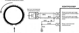
The VAZ 2110 induction type crankshaft sensor is installed next to a special disk located together with the crankshaft drive pulley. The special disk is called a reference or master disk. Together with it, it ensures angular synchronization of the operation of the control unit. Skipping two teeth out of 60 on the disk allows the system to determine the TDC of the 1st or 4th cylinder. The 19th tooth after skipping should face the DPKV rod, and the mark on the camshaft should be against the bent reflector bracket. The gap between the sensor and the top of the disc tooth is in the range of 0.8-1.0 mm. The sensor winding resistance is 880-900 Ohms. To reduce noise levels, the crankshaft sensor conductor is shielded.
After turning on the ignition, the control program of the unit is in the waiting mode for the synchronization pulse signal from the crankshaft position sensor. When the crankshaft rotates, the sync pulse signal arrives instantly to the control unit, which, in accordance with their frequency, switches the electrical circuit of the injectors and the ignition coil channels to ground.
The control unit program algorithm works on the principle of reading 58 teeth passing by the magnetic core of the DPKV, skipping two. The skipping of two teeth is a reference mark for determining the piston of the first (fourth) cylinder in the top dead center position, from which the unit analyzes and distributes the switching signals that control the opening of the injectors and the spark on the spark plugs over the engine operating strokes.
The control unit detects a short-term failure in the synchronization system and tries to resynchronize the control process. If it is impossible to restore the synchronization mode (lack of contact on the DPKV connector, cable break, mechanical damage or broken master disk), the system issues an error signal to the instrument panel, lighting the Check Engine warning lamp. The engine will stall and it will be impossible to start it.
The crankshaft position sensor is a reliable device and rarely fails, but sometimes malfunctions occur due to the inattentive or negligent attitude of specialists servicing the engine.
The crankshaft position sensor is a reliable device and rarely fails, but sometimes malfunctions occur due to the inattentive or negligent attitude of specialists servicing the engine.
For example, a VAZ-2112 has a 21124 engine (16 valves where the DPKV cable is located very close to the exhaust manifold ) and the problem usually arises after repairs, when the chip on the cable is not secured to the bracket. When the cable comes into contact with a hot pipe, it melts, destroying the connection circuit and the car stalls.
Another example could be a poorly manufactured drive disc , the rubber coupling of which can rotate along the internal connection.
The electronic control unit, receiving a single signal from the DPKV, determines the position relative to the crankshaft at each moment of time, calculating its rotation frequency and angular velocity.
Based on sinusoidal signals issued by the crankshaft position sensor, a wide range of problems are solved:
- Determination at a given time of the position of the piston of the first (or fourth) cylinder.
- Control of fuel injection timing and injector open duration.
- Ignition system control.
- Control of variable valve timing system;
- Control of the fuel vapor absorption system;
- Ensuring the operation of other additional systems related to engine speed (for example, electric power steering).
Thus, the DPKV ensures the functioning of the power unit, determining with high accuracy the operation of its two main systems - ignition and fuel injection.
Before purchasing a DPKV to replace it, you need to clarify the type of device installed on the engine.
Functions and purpose of the VAZ 2110 crankshaft sensor
On an engine with 8 or 16 valves, the DPKV is designed to perform not control options, but to implement phase synchronization for gasoline injection. Also, the crankshaft sensor on the VAZ 2110 transmits an impulse to ignite the air-fuel mixture in the combustion chambers of the power unit. Therefore, if the controller breaks down, this can lead to various vehicle systems not functioning coherently. This means that normal operation of the engine will be impossible.
VAZ 2112 crankshaft sensor
The VAZ 2110 crankshaft sensor itself is an inductive type device; this controller must respond to the passage of teeth on the master disk. This disk is mounted on the generator drive pulley, and the controller itself is installed next to it. There are 58 teeth on the pulley, between which there is a cavity the size of 2 teeth. This cavity allows synchronization with the top dead center of the engine pistons. The moment the depression passes the controller, a corresponding signal is sent to the engine control unit.
There are quite a few designs of devices of this type; the principle of their operation is based on a regulator such as the VAZ 2110 Hall sensor. In the latter case, the regulator also responds to a rotating shaft, but its operation is carried out as a result of the passage of a permanent magnet.
Inductive (magnetic) crankshaft sensor VAZ 2110
The device is based on a magnetized core placed in a coil. At rest, the magnetic field is constant and there is no self-induction emf in its winding. When the top of the metal tooth of the driving disk passes in front of the magnetic core, the magnetic field around the core changes, which leads to the induction of current in the winding. When the disk rotates, an alternating current appears at the output, and the frequency of the current varies depending on the speed of the shaft rotation. The work is based on the effect of electromagnetic induction.
A special feature of this sensor is its simple design, which operates without additional power supply.
Hall effect sensor
The type of these sensors operates on a microcircuit, placed in a housing with a magnetic core, and the drive disk creates a moving magnetic field with magnetized teeth.
The sensor provides high accuracy of signal output in all specified crankshaft rotation modes. A sensor operating on the basis of the Hall effect requires a constant voltage connection.
Optical sensors
It is based on the physical phenomenon of the photoelectric effect. Structurally, it is a light source with a receiver (photodiode). Rotating between the source and the receiver, the perforated disk periodically closes and opens the path to the light source, as a result the photodiode produces a pulse current that arrives in the form of an analog signal to the control unit (the system has limited use and was previously installed in the distributors of injection cars, for example, Matiz).
Where is the crankshaft sensor located on the VAZ 2110?
If malfunctions are noticed in the operation of the engine, then before you begin to identify the breakdown and signs of malfunction, you need to find out where the regulator is located. Where is the crankshaft position sensor located on an 8- or 16-valve “ten”? If you open the hood, you will notice that the regulator can be found directly on the oil pump cover. As you can see, the location of the regulator is not particularly convenient. VAZ engineers thought through this point, thinking about the convenience of replacing the controller, so they equipped the DPKV with a long 80 cm wire.
Location of the DPKV under the hood of the car
What cars is the crankshaft position sensor suitable for?
| Model | Engine code | Year | Engine capacity, l. |
| 110 (2110) 1.5 | BA3 2111 / VAZ-2111 | 1995 — 2005 | 1,5 |
| 110 (2110) 1.5 16V | VAZ-2112 | 1995 — 2010 | 1,5 |
| 110 (2110) 2.0 i | C 20 XE | 1996 — 2000 | 2 |
| 110 (2110) Wankel | VAZ-415 | 1997 — 2004 | 2,6 |
| 110 (2110) 1.6 | VAZ-21114 / VAZ-21124 | 1995 — 2012 | 1,6 |
| 110 (2110) 1.6 16V | VAZ-21124 | 2004 — 2010 | 1,6 |
| 110 (2110) 1.6 LPG | VAZ-21114 | 2004 — 2007 | 1,6 |
| 111 (2111) 1.5 | VAZ-2111 / BA3 2111 | 1996 — 2005 | 1,5 |
| 111 (2111) 1.5 16V | VAZ-2112 | 1995 — 2005 | 1,5 |
| 111 (2111) 1.6 | VAZ-21114 / VAZ-21124 | 2004 — 2013 | 1,6 |
| 112 (2112) 1.5 | VAZ-2111 | 1995 — 2005 | 1,5 |
| 112 (2112) 1.5 16V | VAZ-2112 | 1995 — 2005 | 1,5 |
| 112 (2112) 1.6 | VAZ-21124 / VAZ-21114 | 2005 — 2011 | 1,6 |
Messages 3
1 Topic by xdcden 2016-03-20 13:31:47
Topic: Resolved: No voltage at DPKV block
there is no voltage on the DPKV block, with the ignition off 0.05v on the white wire and ground, and 0.83v when turned on. on the green wire at zeros, where to look for what? the fuel pump is working, there is no spark.
2 Reply from Seryoga Sedovlasy 2016-03-20 15:00:35
xdcden, Depending on which ECU. But the general test scheme is as follows: Turn off the ignition, disconnect the harness connector from the controller, measure the resistance between the contacts coming from the DCPV with a multimeter (different ECUs have different contact numbers) a) if the resistance is 750 Ohms or more, the connecting wires or sensor are faulty; b) if the resistance is 550 Ohms or less, the wires are shorted to each other or the sensor is faulty; c) if the resistance is within 550-750 Ohms, rotate the crankshaft, using a multimeter to measure the voltage between the contacts of the harness block. If the voltage is below 0.3 V, the connections are faulty or the sensor is faulty. If the voltage is higher than 0.3 V, connect the harness block to the controller, clear errors from the controller’s RAM and try to start the engine. PS The sensor itself generates voltage pulses when the teeth of the crankshaft pulley pass by it
3 Reply from xdcden 2016-03-22 08:13:40
Seryoga Sedovlasy, thanks for the advice. It was decided, it wouldn’t start due to the fact that the wires on the block were mixed up.
Methodology for checking the functionality (diagnostics) of phase sensors (part 21110/21120-3706040) and crankshaft position sensors (part 21120-3847010), used on VAZ cars.
1. Checking the phase sensor 21110-3706040
1.1 Set the voltage on the voltmeter V1 on the power supply E to 13.5±0.5V, the voltage at contact “B” of the sensor must be at least 0.9Up. 1.2 Bring a steel plate made of soft magnetic material to the end of the sensor, as shown in the figure. The sensor should operate, which is determined by the change in voltage at contact “B” of the sensor. When the sensor is triggered, the voltage at contact “B” should be no more than 0.4V. 1.3 Remove the steel plate, and the voltage at contact “B” of the sensor should change to a value of at least 0.9 Up.
2. Checking the phase sensor 21120-3706040
2.1 Set the voltage at voltmeter V2 on power supply E to 13.5±0.5V, the voltage at contact “B” should be no more than 0.4V. 2.2 Bring a steel plate made of soft magnetic material with a width of at least 20 mm, a length of at least 80 mm and a thickness of 0.5 mm to the end of the sensor as shown in the figure, placing it in the slot of the housing. The voltage at contact “B” of the sensor must change and be at least 0.9 Up. 2.3 Remove the steel plate, and the voltage at contact “B” of the sensor should change to a value of no more than 0.4V
II. Checking the performance of DPKV (21120-3847010)
1.1 Remove the sensor. Carry out an external inspection of the sensor for damage to the sensor body, core, contact block and its contacts. Contacts must be clean. If there is contamination on the contacts, remove them with an alcohol-gasoline mixture. If the core is dirty, clean it of metal particles and dirt. 1.2 Check the active resistance of the sensor winding between contacts 1 and 2 of the sensor block using a V7-22A digital voltmeter (or another that provides similar or greater measurement accuracy). The value of active resistance should be in the range of 550-750 Ohms. Checking the active resistance of the sensor should be carried out at a sensor temperature of 22±2°C. When checking active resistance, it is necessary to take into account the error of the measuring device. 1.3 Check the inductance of the sensor winding between contacts 1 and 2 of the block using an R, L, C E7-8 meter at a frequency of 1 kHz. The inductance value should be in the range of 200-420 mH. 1.4 Check the insulation resistance of the sensor between the core and the sensor terminals (contacts 1 and 2 of the block) using a F4108/1 megohmmeter. The insulation resistance must be at least 20 MOhm at a voltage of 500V.
Version 24.10.16 beta
[td] Car reference book
Moving the site to a new domain.
Crankshaft position sensor (CPS)
VAZ ECM sensors. The sensors convert the information into an electrical signal, which is received by the electronic engine control unit. The presence of all sensors is not necessary for the ECM to function. The configurations depend on the injection system and toxicity standards.
To check the DPKV itself, you need to remove it from the car by unscrewing the mounting bolt and removing the sensor from the hole in the boss on the oil pump housing. By connecting the tester to the sensor terminals, measure the resistance; it should be equal to 550-750 Ohms. Then we switch the tester to the alternating current measurement mode and bring a screwdriver or other metal object to the sensor; the tester should detect voltage surges.
You can check the serviceability of the DPKV sensor using a scanner, which must be connected to the diagnostic connector.
The best and most accurate test for crankshaft position sensor operation. You can do this with a motor tester (oscilloscope).
Technological progress in the automotive industry is displacing outdated carburetor engines, replacing them with injection ones. This leads to the need to know the design and operating principle of modern engines, in terms of the synchronization of spark formation and the supply of gasoline to the cylinders. DPKV is not provided on cars that do not have an on-board computer, and on carburetor engines.
The sensor is available in the design of only injection and diesel internal combustion engines. The stable functioning of a modern car depends on the ECU, which is its “brain”. The unit receives information about the condition of the vehicle from the installed sensors, which is processed, and based on the results obtained, the operation of all systems is adjusted. One of the main sensors responsible for engine operation is the crankshaft position sensor.
Features of injection systems
The injection system operates thanks to a sensor system and a control unit. All signals are input to the microprocessor unit, which regulates the operation of the actuators. The following sensors are responsible for the correct operation of the engine:
- Crankshaft positions.
- Camshaft positions (not on all versions).
- Intake manifold pressure.
- Lambda probe.
- Speed.
- Mass air flow.
- Throttle position.
And the main role is played by the VAZ-2110 crankshaft sensor (8 valves or 16), since the moment of injection and supply of high voltage to the spark plug electrodes depends on it. The design has a temperature sensor, but it has virtually no effect on operation. It is necessary to control the engine temperature and send a signal to the dial indicator (or to the on-board computer). But it will be indispensable if it is necessary to implement automatic switching of fuel types (from gasoline to gas and back).
Algorithm of operation of the injection system
The microprocessor has several inputs and outputs. The inputs receive signals from all sensors. But first, these signals are converted and, if necessary, amplified. The microcontroller is programmed to work with sensors and actuators. Programs (firmware) can provide various engine characteristics.
You can achieve an increase in power (gasoline consumption will increase) or a decrease in consumption (power will suffer). But most motorists prefer programs that provide work with average parameters. In this case, the signal from the VAZ-2110 crankshaft position sensor does not change; only the reaction of the actuators to changes in input data is adjusted.
Why do you need a timing sensor?
DPKV records and transmits the following indicators to the ECU:
- the moment the pistons pass TDC and BDC in the first and last cylinders;
- crankshaft position measurement.
The received data is transmitted to the ECU. As a result of processing information about the position of the crankshaft in relation to the dead points and its rotation frequency, the synchronization sensor corrects the following indicators of the internal combustion engine:
- the volume of gasoline entering the cylinders;
- fuel supply time;
- ignition timing;
- camshaft rotation angle;
- moment and duration of operation of the adsorber valve.
The tasks of the electronic unit may vary depending on the complexity of the internal combustion engine device, but not a single ECU operates without a crankshaft position sensor.
As a result of a malfunction of the DPKV, sparking is either delayed or ahead of the engine's power stroke, which leads to improper operation of the internal combustion engine or to the engine not starting. This contributes to incomplete combustion of the working mixture and, as a result, excessive fuel consumption and a decrease in the dynamic performance of the car.
A little about the crankshaft
The crankshaft is the most important element of any internal combustion engine. It is driven by the starter (at the moment of starting) and the pistons (in operating mode). From it, torque is transmitted to the gearbox, gas distribution system, and auxiliary mechanisms. And in order for fuel injection to be carried out in a timely manner, a spark to form at the right moment, a VAZ-2110 crankshaft sensor is needed.
It monitors the position of the pulley and transmits a signal to the electronic control unit. The pulley has teeth, the distance between them is the same. But in one place there is a gap - two teeth are missing. The position sensor reacts to the approach of metal. When an empty area passes near the sensor, a signal is generated - the control unit is notified that one revolution of the crankshaft has occurred.
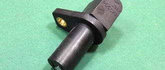
DPKV device
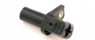
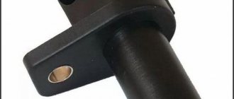
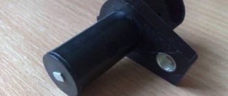
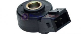
The part is a steel core with a copper wire winding, placed in a plastic case and filled with compound resin.
There are 3 types of synchronization sensors available:
- Induction. The operating principle is based on the use of a magnetized core with copper wire wound on it, at the ends of which the change in voltage is measured. In addition to fixing the position of the crankshaft, it measures its rotation speed, which is also necessary for high-quality operation of the internal combustion engine. Induction sensors are the most common and frequently used in automobile devices.
- Optical. Their design is based on an LED, which emits a luminous flux, and a receiver, which captures the light on the other side. When a light beam hits a control tooth, it is interrupted, the receiver records its absence, and the information is transmitted to the computer.
- Hall Sensor. It works based on the physical effect of the same name. A magnet is placed on the crankshaft; when it passes the sensor, a direct current appears in the latter, fixed by a synchronizing disk.
The versatility of an induction-type device and a Hall sensor make them the most popular in the design of modern motors.
Replacing chips and pinout of DPKV VAZ 2110
Over time, the wires going to the DPKV chip wear out. Located in the lower part of the engine and not far from the front wheel, as a result, dirt, snow, oil, and aggressive chemical media in the form of salt get on the DPKV and its chip and settle, which leads to slow oxidation of the wires on the chip and subsequently to their breakage. Since the wires from the chip are combined into a single bundle, when replacing it, a repair chip is provided with protruding two wires 15 cm long. Having removed the damaged chip, install a new one with a twist. The twist points are insulated using heat shrink or electrical tape.
From the diagram below it can be seen that their pinout is not complicated and two wires are directly connected to the signal input contacts in the control unit, passing along the entire length of the harness. The polarity of the connection between the signal wires of the sensor and the control unit must be observed. If the polarity is reversed, the synchronization system will not work. To restore the operation of the DPKV, you simply need to swap the wires and check the functionality by starting the engine.
Working principle of the synchronization sensor
For stable operation of the engine, the DPKV working process occurs according to the following principle:
- The crankshaft has a special gear (reference disk) with two missing teeth - start and zero.
- When the crankshaft rotates, the teeth, passing through the magnetic field of the DPKV, change it - as a result, pulses are formed in the device, the data of which is transmitted to the control unit;
- When a gear with missing teeth passes past the sensor, the nature of the pulses changes, and the unit determines the initial position of the crankshaft;
- Based on counting the received pulses, the computer determines the position of the crankshaft in a certain period of time:
- After processing the information, the ECU sends signals to the appropriate vehicle systems, and their operation is adjusted.
As a result, stable operation of the car engine is ensured.
Signs of breakdown
Any malfunction of the VAZ 2110 crankshaft sensor will cause the engine to be unable to start after a long period of parking. If the controller starts to malfunction while operating the car, in 90% of cases the engine will stall, since the ECU will not generate a signal to the ignition system, and the internal combustion engine safety function will work. Signs of a sensor malfunction when the unit begins to break down:
- Check Engine is activated on the dashboard;
- engine speed becomes unstable, traction decreases by 50%;
- The VAZ 2110 crankshaft sensor must be urgently changed if the following sign of a malfunction appears: when the speed increases, a hum is felt in the engine area and knocking;
- An injection engine is characterized by the appearance of popping noises in the exhaust tract area.
When the VAZ 2110 dpkv is completely faulty, the engine stalls because the computer does not send signals to form a spark.
These symptoms do not always indicate that a complete replacement of the VAZ 2110 crankshaft sensor is necessary, since all faults of the element are conditionally divided into four groups:
- surface clogging;
- damage to the winding of the device and violation of its integrity;
- manufacturing defects;
- open circuit or short circuit in the circuit.
Checking the sensor begins with cleaning the part. The cleanliness of the contacts, their security, the cleanliness of the connector are checked, and oil stains are eliminated. The design of the sensor is quite simple, but 20 percent of device failures are factory defects. The wiring break is repaired after ringing the circuit. The VAZ 2110 crankshaft sensor is not repaired, since the cost of the consumable does not exceed 100 rubles; the unit is replaced with a similar one after a short diagnosis.
Functions of the sensor and the threat of its breakdown
The purpose of the crankshaft position sensor (CPS) is to synchronize the supply of gasoline and engine start. The device sends a signal to the electronic control unit, which, in turn, regulates the operation of these systems. The working principle is given below.
When the crankshaft begins to move, a current pulse appears between the installed regulator and the shaft teeth. At this moment, the control unit begins reading pulses and sends a signal to open the injectors. It also sends a signal to the ignition module, after which the latter sends a spark to the spark plugs. Since two teeth are missing on the crank pulley disc, this allows the control unit to determine the position of top dead center. Accordingly, in this way he knows when to send signals to the injectors and a spark to the candles.
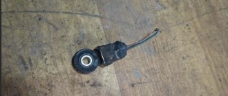
This is what DPKV looks like
The threat of device failure is fraught with the fact that if the DPKV fails, starting the engine will be impossible.
Crankshaft sensor VAZ 2110 Causes of failure
There are a small number of reasons why a sensor may fail, but they still exist.
- Mechanical damage;
- Aging;
- Electrical damage;
- Open circuit control;
Let's consider each of the breakdown options in more detail.
Mechanical damage. May be caused by any impact to the sensor. For example, when trying to dismantle the sensor, similar breakdowns are possible.
Aging. Often on older cars the sensor may fail due to its aging and demagnetization of the core.
Electrical damage. With such a breakdown, the coil inside the sensor most often breaks, and it stops sending a signal to the ECU.
Open circuit control. A break in the control circuit does not refer to a sensor failure. If there is a break, the wiring that transmits the signal from the sensor to the ECU is affected.
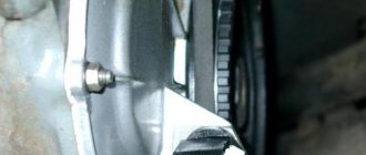
DPKV location - design features
Typically this sensor is located near the alternator belt drive pulley. On this pulley there is usually a gear ring made around the circumference, the so-called synchronization disk. It is to the rotation of this disk that the sensor responds.
It is worth noting that in order to accurately obtain data on the rotation of the crankshaft, the DCPV is located at a certain distance from the disk.
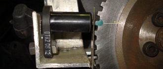
For a correctly installed device, the distance between its core and the top of any tooth should be 0.6-1.5 mm.
The location of the DKPV is not the most convenient, but it is quite possible to get to it.
Cars use several different DPKVs in design and operating principles:
- induction (one of the most common);
- sensor using the Hall effect;
- Optic.
We won’t talk about the design and operation features of each of them for now; let’s move straight to the malfunctions.
Checking the VAZ 2110 crankshaft sensor for serviceability
To verify the suspicion of a breakdown of the crankshaft sensor, the two most likely cases of its malfunction are considered. In both of these cases, you will need to dismantle the device using a ten-threaded wrench. Before the operation, marks are drawn on the crankcase and the sensor itself, which will later help to tighten the device to the initial angle of rotation.
Also, the motorist should not forget to measure the clearance between the synchro disk and the sensor before dismantling, which cannot go beyond the size of 0.6-1.5 mm. If there are no mechanical damage such as scratches, dents, or damage to the material structure, the sensor is checked using other measuring instruments:
- checking with an ohmmeter. In this case, it is necessary to measure the resistance of the sensor winding. Since the standard value of this indicator, set by the manufacturer, ranges from 550 to 750 Ohms, going beyond the specified limits indicates the malfunction of this device, which is important for the correct operation of the car - which means it is faulty. It is worth noting here that the manufacturer still allows a slight discrepancy in resistance with the nameplate values, but in any case they must correspond to the data specified in the machine’s operating instructions;
- checking with a voltmeter, inductance meter and transformer. This method is more complicated, but more effective - the resistance is measured with the same ohmmeter, after which the inductance is checked (should be from 200 to 4000 millihenry), with a sensor winding voltage of 500 Volts. Next, you need to measure the resistance with a megger and make sure that it does not exceed 20 MOhm.
If the sensor still does not pass these tests, it must be replaced. During this procedure, it is necessary not to forget about the distance between it and the synchronization disk regulated by the manufacturer, as well as alignment with the marks on the crankcase that were made on the previous device. Before installing a new sensor, be sure to check it, since even if all installation procedures are followed correctly, it may not work properly.
A new DPKV is checked according to the same procedure as a supposedly faulty one, and based on the test results, the device can be installed instead of the previous one or rejected. When installing, the bolts are tightened with a torque of 8 to 12 Nm. However, in any case, before carrying out all the actions to replace a rather expensive and hard-to-reach component, you should definitely make sure that it is the one that has failed, because cars produced by our automotive industry can often bring unpleasant surprises.
The first way to check the crankshaft sensor VAZ 2110
In this case, you will need an ohmmeter , which you will use to replace the resistance on the winding. According to the manufacturer's standards, the indicator ranges from 550 to 750 Ohms.
It's okay if your numbers are slightly different from the norm. If the deviations are serious, you will definitely have to replace the sensor.
It should be noted in fairness that the crankshaft position sensor on VAZ 2110 models rarely breaks down. Among the main reasons for its failure to function normally is the accumulation of dirt, mechanical damage, as well as banal factory defects.
Features of testing on other cars
As for other cars, for example, VAZ-2109 with an injection engine, VAZ-2112 and VAZ-2114, their check is carried out identically to the VAZ-2110 car.
It is noteworthy that for VAZs, when checking the resistance of the crankshaft sensor coil, an additional check can be carried out.
But to do this, the multimeter must be switched to voltmeter mode with a measurement limit of 200 mV.
Then connect the probes to the DPKV terminals and pass them with any metal object, for example, a screwdriver, at a short distance from the core.
If the sensor is working properly, it will react to metal, the multimeter will show voltage surges on the display. The absence of these bursts will indicate a faulty element.
As for a car like the Reno Logan, the difference from the VAZ in this car comes down to slightly different readings of the resistance of the sensor coil when measured with an ohmmeter.
A working Logan DPKV has a normal resistance of 200-270 Ohms.
For Daewoo Lanos, the coil resistance should be in the range of 500-600 Ohms.
But on the ZMZ-406 engine, installed on Volga and Gazelle cars, the normal coil resistance is in the range of 850-900 Ohms.
Second method
Here you will need a voltmeter, a transformer and an inductance meter. It is advisable to measure resistance under compact temperature conditions.
Once the ohmmeter readings are obtained, arm yourself with an inductance measuring device. Normally, the device should show from 200 to 4000 units (millihenry).
A megger measures the resistance when the crankshaft position sensor winding is powered at 500 volts. Under normal conditions, the readings will be no more than 20 MΩ.
Important points
Drivers note that not all sensors that have a suitable mounting size are suitable for working on a VAZ 2110. You can only replace the sensor with an original one, after first checking the part for functionality. A resistance test must be carried out before installation on a car; according to statistics, 1–3% of VAZ sensors have manufacturing defects.
The equipment can be considered operational only after a preliminary manual check with an ohmmeter. Things to consider.
- Be sure to mark the pulley when reinstalling the part. The ideal option would be to check with a scanner that the sensor is installed correctly. Any displacement of the crankshaft will lead to disruption of the fuel supply phases.
- Observe the sensor pinout. Select equipment with suitable terminal tolerances.
- Tighten the fastening bolt to a torque of 8–12 nm, do not overtighten.
- Leave a gap between the controller and the transfer disk.
Replacing the control device takes a few minutes; the work can be easily done in the garage. If you systematically remove oil stains from the tank, clean the engine compartment from dirt, and monitor the condition of the wiring, the DPKV will fulfill the service life declared by the manufacturer - 5–7 years.
Controller diagnostics
Diagnostics of the crankshaft position sensor is carried out on the dismantled controller. It is recommended to set a timing mark on the crankcase before removing it so that when installing a new element, the correct gap between the tracking device and the timing disk will be maintained. The permissible gap is 0.6–1.5 mm.
We remove the element with a 10mm wrench and carry out a visual inspection. Before checking the crankshaft sensor, the battery is disconnected and the contact points are checked. During a visual inspection, the integrity of the housing, wires, connectors, and the absence of cracks and dents on the housing are checked. If there are no signs of mechanical damage, the DPKV is checked with a multimeter.
Testing of the node can be carried out both by resistance and voltage parameters. Testing for resistance is much simpler, so it is used in most diagnostic options.
The resistance on the working controller winding should be in the range of 550–750 Ohms. Measurements are taken on two contacts of the part. For a 16-valve injector engine, a resistance deviation of 5% is considered acceptable.
Drivers rarely use the second testing option, although diagnostics with a voltmeter are considered more reliable. To check, you will need a transformer and an inductance meter, for example, the MY-6243 multimeter model is often used to measure capacitance and inductance. Checking step by step.
- Calculate the inductance dpkv. The working element at a voltage of at least 500 mV will show an inductance in the range of 200–4000 iH.
- Check the resistance; a working sensor shows a parameter of 20 mOhm.
Comprehensive check for Opel Vectra B
Now let's take another car and use it to consider the last of the verification methods - comprehensive.
This test is much better than with a conventional multimeter, but in terms of accuracy it is not as accurate as an oscilloscope.
The problem car will now be the Opel Vectra B. We leave the symptoms the same.
The initial work is also no different from the VAZ-2110: the sensor is removed, inspected, thoroughly washed, and only after that you can start checking the condition.
But for a comprehensive check you will need more equipment:
- Multimeter;
- Megaohmmeter;
- Device for measuring inductance.
It is better to take all measurements in a heated room so that the readings are correct.
First, the coil resistance is measured, as described above. Resistance readings must be within the range specified in the technical documentation.
The next check is to measure the winding inductance, for which a device is used to measure it. A working DPKV inductance should be in the range of 200-400 mH.
The devices are pictured below.
The insulation resistance is also checked with a megohmmeter. When a voltage of 500 V is applied, the resistance value of the sensor should be no more than 20 MΩ.
Based on these measurements, it is determined whether the DPKV is working or requires replacement.
Photos of the devices are below.
To change or not to change the crankshaft sensor of the VAZ 2110?
Let’s make a reservation right away: before deciding that the DPKV needs replacement, you need to check:
- Condition of the wiring going to the DPKV;
- Availability of high-quality contacts in the circuit;
- No damage to wire insulation;
- No oil on the crankshaft position sensor. Since the oil pump is located next to the DPKV, oil leakage can also cause its malfunction.
Functional crankshaft position sensor
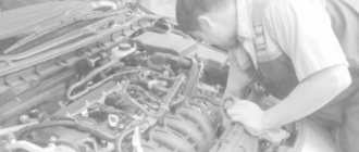
If you have already examined everything, you need to check the sensor itself. But to do this you need to remove it.
How does he work
Let's figure out how this element works. The regulator reads data on the crankshaft speed and also reports its current position using magnetic pulses.
Location
Since the engines installed on the VAZ 2110 differ from each other, different PCV sensors are used. Therefore, when replacing, be sure to choose a similar device, since a regulator with other characteristics simply will not work, so the system will still not work even if you have a high-quality, serviceable sensor.
Replacement
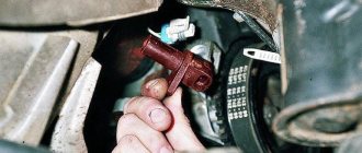
If signs of a malfunction of the DPKV are associated with damage to the device, it is replaced without repair. The controllers are located in an inconvenient place; they are attached to the oil pump cover with a single bolt. How to remove an element step by step.
- The ignition is turned off, the negative terminal of the battery is removed.
- The oil pump where the sensor is located is determined, and the connector is removed. There is an 80 cm wire from the controller to the block; you can determine the location of the connector by the wire.
- Use a 10mm wrench to unscrew the only screw.
- The device is removed.
Before installing a new element, you must thoroughly clean the sensor seat and connector plug, and check the integrity of the wiring. This will avoid rapid failure of the new part.
If the problem in the operation of the internal combustion engine is due to the lack of a signal from the sensor connector on the computer, check the integrity of the wiring. Electronics diagnostics, if there is a signal but no response from the electronic unit, are carried out in a specialized workshop. In 90% of cases, flashing of the control system and replacement of electronic components is required.
In half of the cases, the sensor fails due to simple dirt. The controller is located in close proximity to the oil pump, which can throw out drops of liquid. Oil getting on the sensor reading element clogs the surface, oxidizes and interferes with the full transmission of data.
Symptoms of problems
The very first and surest manifestation of a malfunction of the DPKV is that the engine shows absolutely no “signs of life”. In addition, the fact that perhaps the device has not yet completely failed, but is already experiencing interruptions, can be judged if:
- The engine runs unstably at idle;
- The car's power is felt to decrease;
- The number of crankshaft revolutions spontaneously increases or decreases;
- As the load increases, engine detonation is clearly felt;
- The machine starts intermittently.
Engine VAZ 2110
Of course, having only these signs, we can also assume other malfunctions, so you need to check not only the sensor, but also everything that has to do with starting the engine - from the wiring to the fuel pump.
Removal
Removing the crankshaft position sensor is very simple, and you already know where it is located - in the same place as the oil pump. So, let's do the following:
- Turn off the ignition;
- Remove the negative terminal from the battery;
- Remove the connector with the wire from the sensor body;
Disconnect the wiring harness from the crankshaft position sensor - Using a 10mm wrench, unscrew the screw holding the DPKV to the oil pump cover;
Unscrew the bolt (1) and remove the DPKV (2) - We remove the device.
Functionality check
To check whether the crankshaft position sensor is working, you need to measure the resistance of its windings using an ohmmeter or multimeter. Normal readings are 550 – 570 Ohms.
If they differ from these numbers, then a replacement with a new one is needed. The old one cannot be repaired, but it is inexpensive, and replacing it is as easy as shelling pears, following the reverse removal algorithm.
Sources
- vazweb.ru/desyatka/dvigatel/datchik-kolenvala.html
- luxvaz.ru/vaz-2110/90-datchik-polozheniya-kolenchatogo-vala.html
- osensorax.ru/posiciya/datchik-kolenvala-vaz-2110
- drive2.ru/l/6251079/