02 March 2017 Lada.Online 56 016 4
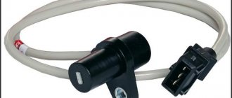
DPKV (crankshaft position sensor), also known as TDC sensor (top dead center sensor) is the only sensor of the engine management system, if which breaks down, the engine will definitely not start. This sensor has no mechanical moving parts, so it rarely fails. Most often, corrosion-damaged wiring is to blame for its failure.
What is a crankshaft position sensor on a vase
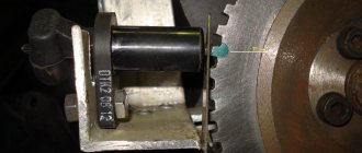
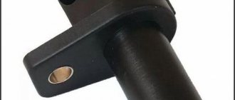
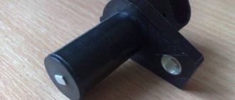
The induction type crankshaft position sensor is installed next to a special disk located in conjunction with the crankshaft drive pulley. The special disk is called a reference or master disk. Together with it, it ensures angular synchronization of the operation of the control unit. Skipping two teeth out of 60 on the disk allows the system to determine the TDC of the 1st or 4th cylinder. The 19th tooth after skipping should face the DPKV rod, and the mark on the camshaft should be against the bent reflector bracket. The gap between the sensor and the top of the disc tooth is in the range of 0.8-1.0 mm. The sensor winding resistance is 880-900 Ohms. To reduce noise levels, the crankshaft sensor conductor is shielded.
After turning on the ignition, the control program of the unit is in the waiting mode for the synchronization pulse signal from the crankshaft position sensor. When the crankshaft rotates, the sync pulse signal arrives instantly to the control unit, which, in accordance with their frequency, switches the electrical circuit of the injectors and the ignition coil channels to ground.
The control unit program algorithm works on the principle of reading 58 teeth passing by the magnetic core of the DPKV, skipping two. The skipping of two teeth is a reference mark for determining the piston of the first (fourth) cylinder in the top dead center position, from which the unit analyzes and distributes the switching signals that control the opening of the injectors and the spark on the spark plugs over the engine operating strokes.
The control unit detects a short-term failure in the synchronization system and tries to resynchronize the control process. If it is impossible to restore the synchronization mode (lack of contact on the DPKV connector, cable break, mechanical damage or broken master disk), the system issues an error signal to the instrument panel, lighting the Check Engine warning lamp. The engine will stall and it will be impossible to start it.
The crankshaft position sensor is a reliable device and rarely fails, but sometimes malfunctions occur due to the inattentive or negligent attitude of specialists servicing the engine.
For example, a VAZ-2112 has a 21124 engine (16 valves where the DPKV cable is located very close to the exhaust manifold) and the problem usually arises after a repair, when the chip on the cable is not secured to the bracket. When the cable comes into contact with a hot pipe, it melts, destroying the connection circuit and the car stalls.
Another example would be a poorly manufactured drive disc, the rubber coupling of which may rotate along the internal connection.
The electronic control unit, receiving a single signal from the DPKV, determines the position relative to the crankshaft at each moment of time, calculating its rotation frequency and angular velocity.
Based on sinusoidal signals issued by the crankshaft position sensor, a wide range of problems are solved:
- Determination at a given time of the position of the piston of the first (or fourth) cylinder.
- Control of fuel injection timing and injector open duration.
- Ignition system control.
- Control of variable valve timing system;
- Control of the fuel vapor absorption system;
- Ensuring the operation of other additional systems related to engine speed (for example, electric power steering).
Thus, the DPKV ensures the functioning of the power unit, determining with high accuracy the operation of its two main systems - ignition and fuel injection.
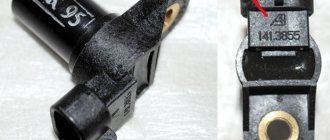
Before purchasing a DPKV to replace it, you need to clarify the type of device installed on the engine.
Symptoms of a problem
A malfunction of the crankshaft sensor leads to unpleasant consequences for the car:
- at idle speed the car may stall;
- tripping and jerking are noted during movement;
- fuel consumption increases significantly, since the electronics do not provide optimal supply of the fuel-air mixture and spark;
- traction weakens, the car refuses to start, or at idle the speed either rises or falls;
- the operation of the injectors responsible for fuel injection is disrupted, the operation of the ignition system changes;
- an indication appears on the dashboard.
Injecting a fuel-air mixture that does not coincide with the appearance of a spark leads to consequences that are difficult to predict.
In some cases, the symptoms observed by the car owner coincide with how the car behaves when the oxygen sensor fails. When the car does not have an on-board computer capable of indicating a possible malfunction with an appropriate indication, a sensor check is required. The car enthusiast can do it himself or go to the nearest service station.
Types of crankshaft sensors
Inductive (magnetic) DPKV
The device is based on a magnetized core placed in a coil. At rest, the magnetic field is constant and there is no self-induction emf in its winding. When the top of the metal tooth of the driving disk passes in front of the magnetic core, the magnetic field around the core changes, which leads to the induction of current in the winding. When the disk rotates, an alternating current appears at the output, and the frequency of the current varies depending on the speed of the shaft rotation. The work is based on the effect of electromagnetic induction.
A special feature of this sensor is its simple design, which operates without additional power supply.
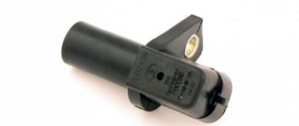
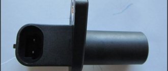
Hall effect sensor
The type of these sensors operates on a microcircuit, placed in a housing with a magnetic core, and the drive disk creates a moving magnetic field with magnetized teeth.
The sensor provides high accuracy of signal output in all specified crankshaft rotation modes. A sensor operating on the basis of the Hall effect requires a constant voltage connection.
Optical sensors
It is based on the physical phenomenon of the photoelectric effect. Structurally, it is a light source with a receiver (photodiode). Rotating between the source and the receiver, the perforated disk periodically closes and opens the path to the light source, as a result the photodiode produces a pulse current that arrives in the form of an analog signal to the control unit (the system has limited use and was previously installed in the distributors of injection cars, for example, Matiz).
Messages 3
1 Topic by xdcden 2016-03-20 13:31:47
Topic: Resolved: No voltage at DPKV block
there is no voltage on the DPKV block, with the ignition off 0.05v on the white wire and ground, and 0.83v when turned on. on the green wire at zeros, where to look for what? the fuel pump is working, there is no spark.
2 Reply from Seryoga Sedovlasy 2016-03-20 15:00:35
xdcden, Depending on which ECU. But the general test scheme is as follows: Turn off the ignition, disconnect the harness connector from the controller, measure the resistance between the contacts coming from the DCPV with a multimeter (different ECUs have different contact numbers) a) if the resistance is 750 Ohms or more, the connecting wires or sensor are faulty; b) if the resistance is 550 Ohms or less, the wires are shorted to each other or the sensor is faulty; c) if the resistance is within 550-750 Ohms, rotate the crankshaft, using a multimeter to measure the voltage between the contacts of the harness block. If the voltage is below 0.3 V, the connections are faulty or the sensor is faulty. If the voltage is higher than 0.3 V, connect the harness block to the controller, clear errors from the controller’s RAM and try to start the engine. PS The sensor itself generates voltage pulses when the teeth of the crankshaft pulley pass by it
3 Reply from xdcden 2016-03-22 08:13:40
Seryoga Sedovlasy, thanks for the advice. It was decided, it wouldn’t start due to the fact that the wires on the block were mixed up.
Methodology for checking the functionality (diagnostics) of phase sensors (part 21110/21120-3706040) and crankshaft position sensors (part 21120-3847010), used on VAZ cars.
How to check the VAZ crankshaft sensor
The VAZ inductive-type crankshaft sensor is checked with a multimeter for breaks inside the coil and the specified resistance, the value of which is in the range of 600-900 Ohms. It is also mandatory to check the DPKV wiring.
The test can be carried out by measuring inductance; for this you need to have three instruments: a voltmeter, a transformer and an inductance meter. The method is not complicated, but cumbersome and it is more efficient to buy a new sensor to check the performance of the engine.
The DPKV can also be checked by cranking the starter while observing the tachometer readings. Using a diode test, you can check for the presence of pulses at the injector connector.
Comprehensive check for Opel Vectra B
Now let's take another car and use it to consider the last of the verification methods - comprehensive.
This test is much better than with a conventional multimeter, but in terms of accuracy it is not as accurate as an oscilloscope.
The problem car will now be the Opel Vectra B. We leave the symptoms the same.
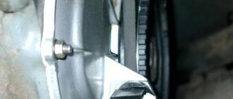
The initial work is also no different from the VAZ-2110: the sensor is removed, inspected, thoroughly washed, and only after that you can start checking the condition.
But for a comprehensive check you will need more equipment:
- Multimeter;
- Megaohmmeter;
- Device for measuring inductance.
It is better to take all measurements in a heated room so that the readings are correct.
First, the coil resistance is measured, as described above. Resistance readings must be within the range specified in the technical documentation.
The next check is to measure the winding inductance, for which a device is used to measure it. A working DPKV inductance should be in the range of 200-400 mH.
The devices are pictured below.
The insulation resistance is also checked with a megohmmeter. When a voltage of 500 V is applied, the resistance value of the sensor should be no more than 20 MΩ.
Based on these measurements, it is determined whether the DPKV is working or requires replacement.
Photos of the devices are below.
Replacing chips and pinout of DPKV VAZ 2110
Over time, the wires going to the DPKV chip wear out. Located in the lower part of the engine and not far from the front wheel, as a result, dirt, snow, oil, and aggressive chemical media in the form of salt get on the DPKV and its chip and settle, which leads to slow oxidation of the wires on the chip and subsequently to their breakage. Since the wires from the chip are combined into a single bundle, when replacing it, a repair chip is provided with protruding two wires 15 cm long. Having removed the damaged chip, install a new one with a twist. The twist points are insulated using heat shrink or electrical tape.
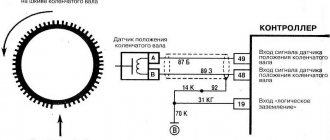
From the diagram below it can be seen that their pinout is not complicated and two wires are directly connected to the signal input contacts in the control unit, passing along the entire length of the harness. The polarity of the connection between the signal wires of the sensor and the control unit must be observed. If the polarity is reversed, the synchronization system will not work. To restore the operation of the DPKV, you simply need to swap the wires and check the functionality by starting the engine.
Oscillogram of DPKV VAZ
An oscilloscope is used to accurately diagnose the operation of the DPKV. By connecting the oscilloscope probes, an oscillogram of the DPKV operation will be displayed on the monitor screen, on which you can clearly distinguish the point where the teeth skipped and measure the signal value in volts based on the maximum amplitude of the 58 teeth located between the skip points.
Using an Oscilloscope
This method is the most reliable and with its help you can be 100% sure of the current state of the sensor. To do this, you need to turn on the oscilloscope to a limit of 10 ms and an amplitude of 1 V/div. And try to start the engine with the starter. In this case, on a well-charged battery, the engine should be accelerated by the starter to 800 rpm, this will correspond to a frequency of 200 Hz and a corresponding period of 5 ms/div. You should observe impulses, one period of which occupies two cells.