A modern car is now equipped with a variety of active safety systems, the list of which is growing every year. These also include a system to prevent wheel locking during braking - ABS (Anti-lock braking system).
ABS is one of the very first safety systems that began to be used on a car, and it is now found on almost all cars, from budget categories to premium ones.
Let's briefly consider the purpose of ABS - this system is needed so that the wheels do not lock during braking, but continue to rotate, albeit at a slower rate.
Thanks to this, the grip of the wheel on the road surface is not lost and the likelihood of the car skidding is completely eliminated, the car remains fully controlled by the driver.
ABS has been used in vehicles for a long time and has proven its effectiveness more than once.
This system works simply. There is an electronic unit that controls the deceleration rate of each wheel. And if one of them stops faster than others, the block reduces the force of fluid pressure in the brake caliper on this particular wheel, that is, the brake mechanism begins to act less.
You can read more about the ABS device and other information on this system here.
What is the ABS sensor for?
It is stated above that the ABS unit, popularly called the “brains” of the braking system, controls the speed of rotation of the wheels, so the design of this system could not be done without sensors.
They are the “sense organs” of this system and based on their readings the ABS functions.
The first anti-lock braking system used only one sensor, which was installed in the axle of rear-wheel drive cars.
But as ABS has improved, their number has increased; modern cars already use 4 sensors. This allows the system to monitor the rotation speed of each wheel individually.
What is the danger of such a situation?
The safety of moving a car lies in complete control over it, under any conditions. While the wheels rotate along the braking distance, the driver directs the car in the desired direction with his own hands. If the car does not have time to stop before the obstacle, you can go around it. But modern brakes are so powerful that the wheels lock on even the slightest slippery surface, and sometimes even on dry asphalt. In Moscow, the speed limit on the Moscow Ring Road is up to 110 km/h. Under such conditions, even the most advanced tire will slip when braking.
What should automakers do? Reduce braking force? It is unacceptable.
In the 70s of the last century, a solution was found: the anti-lock braking system (ABS).
The technology allows you to maintain vehicle controllability during braking. The wheels are not blocked, therefore, the car obediently follows the steering.
Types of sensors
There are three types of such elements, differing in their operating principle. The most common passive sensors are induction type.
The essence of their work comes down to a change in voltage due to the influence of a magnetic field. Their main disadvantage is the inability to determine the speed of rotation of the wheel at very low speeds.
The remaining two types are active.
One of them is magnetoresistive (rare). The principle of its operation is based on the magnetoresistive effect - the property of a semiconductor to change the trajectory of electrons when exposed to a magnetic field.
The second type of active sensor uses the Hall effect, in which electrons on a semiconductor wafer move to its edges when the magnetic field changes.
Sensor Features
There are several significant differences between passive and active types. They are called passive because they do not require voltage to operate; such a sensor itself generates electrical impulses, to which the electronic unit reacts. Active elements require voltage to be applied to them.
Passive elements are very simple in design and are very reliable. That's why they are so common, despite their shortcomings.
Active types of sensors use microcircuits in the design, which complicates the element and makes it more vulnerable. But they are highly accurate and do their job even at low speeds.
Since all types of sensors operate under the influence of a magnetic field, it alone is not enough in the design; another element is needed to which it would react.
The induction (passive) type uses a ferromagnetic alloy pulse gear ring mounted on the drive hub or shaft, as well as on the steering axle. Previously, it could also be mounted on the bevel gears of the main drive.
In active types, a magnetic pulse ring is used. In the case of a magnetoresistive sensor, this ring is divided into alternating sectors with permanent magnets of different polarities.
But the Hall sensor uses a regular magnetic ring, without any sectors, integrated into the wheel bearing.
Briefly about the principle of operation
The ABS function simulates the harsh, repeated pressure on the brake pedal experienced by drivers of older cars on slippery roads. Electronics uses this method of braking much more efficiently, locking and “releasing” the wheels several times per second. The operating algorithm is as follows:
- During sudden braking, the control unit monitors the behavior of the wheels using sensors.
- If one or more wheels stop rotating, the ECU issues a command to a hydraulic valve that releases fluid from that circuit. The pads stop holding the disc and rotation resumes.
- By comparing the readings of all meters, the controller makes sure that braking is not complete and closes the hydraulic valve, and the wheel is blocked again. The cycle, lasting a fraction of a second, is repeated until the machine stops completely.
Important! If the functionality of one or more sensors is impaired, the ABS will fail entirely, since the electronic unit will not be able to compare the behavior of the wheels.
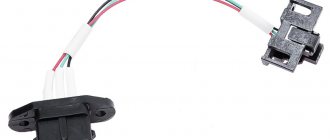
The latest generation ABS sensor is a coil with a semiconductor element installed in a stationary part of the hub. In the immediate vicinity of it, a toothed ring is attached to the brake disc, whose rotation is monitored by a sensor. It happens like this: the controller supplies voltage to the device, and it constantly changes the resistance due to the passage of a series of teeth on a rotating ring.
When the amount of electrical resistance becomes constant, the ECU regards this fact as wheel locking and turns on the above-described algorithm. If the element fails, the ABS system is completely disabled.
Inductive type element design
Since inductive sensors are the most common, their design will be considered in the future.
Such a sensor consists of an inductive coil, inside of which a magnetic core is placed. It is installed next to the toothed impulse ring, but so that there is a certain gap between them.
When the wheel rotates, the ring teeth pass through the magnetic field created by the core, which affects the magnetic flux, causing the alternating voltage value in the coil winding to change.
As a result, the speed of rotation of the wheel, and with it the pulse ring, affects the frequency and amplitude of oscillations of the output voltage on the coil. These parameters are fed to the “brains”, as a result of which they estimate the speed of deceleration of the wheel.
Problems with at least one of the ABS sensors can lead to a complete shutdown of the system. And although the braking system on the car will work, you can forget about the braking efficiency and safety that ABS provided.
Clearing Diagnostic Codes
Necessary equipment
Scan ToolDiagnostic codes can be cleared from the brake controller memory as follows:
- Select the "Clear DTCs" command on the scan tool.
Detailed instructions are provided below. Once clearing is complete, verify that the system is functioning normally and that there are no codes present. The controller will not allow codes to be cleared until all codes have been reviewed. Diagnostic codes cannot be cleared by turning off the controller, power to the battery, or turning the ignition switch to the LOCK position.
Causes of sensor malfunction
The induction sensor is characterized by its simple design and high reliability; malfunctions with it occur very rarely. The problem most often lies in the wiring through which signals are sent to the control unit.
Since the sensors and their wiring are located directly next to the wheels, over time the circuit may break or short out. Often, sensor failures occur due to oxidation of the contacts.
Due to the fact that after turning on the ignition on a car, ABS always undergoes self-diagnosis, during which the condition of all elements of the system is assessed, it is quite simple to identify problems with the sensors; if they occur, the warning light will constantly light up on the dashboard.
In total, there are 4 types of system behavior when a malfunction is detected:
- Self-diagnosis detects an error and ABS is disabled. This may be a sign of an error in the control unit, or a break in the wiring coming from the sensor;
- The system undergoes diagnostics, during which no problems are detected, but after this the ABS is turned off. This result usually results from problems with the wiring going to the sensors (oxidation, open circuit, short circuit, etc.);
- Self-diagnosis detects an error, but the system does not turn off and continues to operate. This usually indicates a break in the wiring on one of the sensors;
- ABS does not turn on. This can happen due to a broken wiring, or because the impulse ring is damaged, chipped or broken. This result can also be produced by a heavily worn hub bearing, which is why there is significant play in it.
Since malfunction of ABS often occurs due to wiring, it is quite simple to identify a faulty element and all you need is a multimeter.
Of course, it is better to check using an oscilloscope, since such a device makes it possible to visually assess the amplitude and frequency of voltage fluctuations in the sensor, but not everyone has one.
Next, we’ll figure out how to check the ABS sensor on different cars, although in general the procedure is the same, despite the fact that any type of sensor can be used on different models.
Using an Auto Scanner
For those who are accustomed to troubleshooting car problems with their own hands, the ELM327 auto scanner will be an indispensable assistant when repairing ABS. We have already introduced our readers to this useful gadget. Today it can be purchased at prices ranging from 350 to 1100 rubles. Let us remind you that this miniature device is inserted into a special OBDII diagnostic connector, which many modern cars are equipped with today. Depending on the design features of a particular model, it transmits information about various parameters and errors detected in the vehicle to a smartphone or tablet (via Bluetooth, Wi-Fi or USB). Checking the entire ABS system and finding a faulty sensor using such a device takes a few minutes.
On a note! Negative comments about the capabilities of the ELM327 auto scanner are mainly explained by the fact that users used simple applications. Those who have installed special programs on their smartphones or tablets designed to diagnose specific car brands speak positively about the operation of this gadget.
Check on Ford Focus 2
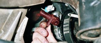
First, let's look at how the test is carried out on a Ford Focus 2. This car uses a Hall effect sensor and is located in the upper part of the wheel hub. It is easy to detect - just remove the wheel, unscrew and move the caliper to the side, and also remove the brake disc.
Before starting the inspection, be sure to check the tire pressure. It must be the same in all wheels, otherwise the pressure difference may affect the performance of the system.
To check the sensor on Focus 2, for ease of access, you should jack up and remove the wheel from the side being tested.
Next, disconnect the block of wires coming from the sensor. We visually assess the condition of the braid and wires; they should not show abrasions or other types of damage.
At the first stage, we check the resistance. To do this, switch the multimeter to ohmmeter mode and connect its probes to the terminals in the block.
On Focus 2, the sensor resistance when measured should be in the region of 1.3-1.4 kOhm.
But there is one nuance that is important to consider. During measurements, you should knead the wire, especially at bends.
The fact is that at the point where the wire is broken, the copper conductors can come into contact, and therefore the sensor can show normal resistance. And during crumpling and bending, contact is broken.
If the readings do not match, a measurement should be taken at the input of the wires to the sensor. This will reveal whether the problem lies in the sensor itself, or just in the wires.
If, when checking the resistance near the element, a discrepancy in resistance remains, then the sensor must be replaced.
In some cases, the cause of the problems lies in contamination of the semiconductor platinum of the Hall element. Therefore, you should remove the sensor itself and clean it.
In addition to the sensor wiring, you should also check the entire circuit for damage. To do this, you need to disconnect the wire block from the control unit.
Then we find out from the technical documentation for the car which terminals on the block correspond to which sensor, after which we connect a multimeter to the necessary connectors and measure the resistance.
If it does not meet the required parameters, you should look for a break in the area from the control unit to the sensor connection block.
Faults such as breaks or short circuits can be treated by replacing the wires. But if the element itself malfunctions, it is replaced.
How to fix problems
After checking the tools and identifying a faulty drive, you can begin repairs. Some owners repair sensors by replacing the wiring or rewinding the coil.
Sensor failure
A faulty passive type sensor can be repaired yourself:
- Remove the sensor from the hub. The fastening bolt often becomes sour, so you need to unscrew it carefully. For removal, it is allowed to use a liquid like WD40.
- Remove the protective coil housing. Removal is done with a file. The cut must be made very carefully so as not to damage the housing and winding.
- Remove the protective film from the packaging by prying it off with a sharp knife.
- Carefully unwind the thread from the bobbin. During the removal process, the version of thread breakage is confirmed. What remains is an empty wire-coil ferrite core.
- Wrap new film. As a core, you can use the copper wire of the common relay coils of the RES-8 type. Winding can be done with a drill with smooth speed control. Be careful because a broken thread will take you back to where you started. It is recommended to wind the wire to the top level of the coil.
- Check resistance. Most coils are in the 0.9-1.2k ohm range. For clarification, it is recommended to measure the parameter on a known-good sensor located on the opposite side of the axis. The resistance is adjusted by unwinding the excess wire. If the reading is low, you will need to use a different stream or rewind. Secure the thread from the self-tapping tape with masking tape or other tape.
- Welding wires at the coil terminals, which serve as a connecting link between the winding and the harness. For terminals, it is recommended to use insulated braided wire, which has a higher resistance.
- Install the coil into the old housing. If during disassembly of the device it received significant damage, the coil is filled with epoxy resin. To do this, the part is placed in a metal cup of a suitable size, for example, a capacitor housing. The air gap between the coil and the glass is carefully filled with resin. When pouring, it is recommended to avoid large air gaps. After the resin has completely hardened, the body is removed.
- Replace the sensor bracket with epoxy resin. Inspect the product for cracks and voids in the insulation. Detected defects are filled with resin.
- Return the repaired sensor to its place and check the operation of the ABS system. When installing the device, it may be necessary to modify the resulting body, which is done with a file and sandpaper. The sensor installed in the field must have a gap between the coil and the toothed ring within the range of 0.9-1.1 mm. When space is reduced, it is recommended to bring it up to standard by installing spacers.
You need to drive the car for some time, checking the brakes at different speeds. There are times when the ABS spontaneously activates at certain wheel speeds, usually just before stopping. Then you will need to look for the gap, correcting it with gaskets or trimming the sensor body.
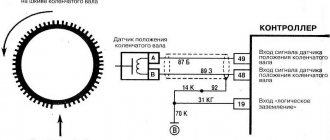
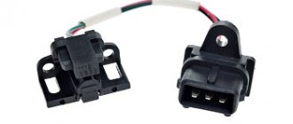
Another repair option is to install a modified crankshaft position sensor from domestic cars:
- We remove the “original” sensor and modify the body of the “donor” part. Most often, this role is played by the DPKV of the ZMZ-406 engine, which has a resistance within 800 Ohms. When remaking, it is necessary to try to ensure that the core is parallel to the wound coil and the toothed ring mounted on the shaft. The distance between the sensor and the ring should be between 0.2 and 0.3 mm.
- Test the operation of the device. On some Japanese vehicles, the ABS warning light may come on intermittently. The situation can be corrected by changing the connection of the wiring contacts.
Both sensor repair options require the owner’s perseverance and ability to work with various tools. If a car user doubts its capabilities, it is recommended to buy a new device or find the product when dismantling cars.
Wiring problem
If the problem with the loss of functionality of the sensor lies in the wiring, it can be replaced:
- Unscrew the sensor holder from the wheel hub.
- Disconnect the cable plug.
- Remove the sensor along with the cable. In this case, it will be necessary to remove the mounting brackets installed on the wiring.
- Measure the installation distances for the brackets. It is recommended to draw a diagram and photograph the factory position of the supports.
- Cut the sensor from the wire, leaving a margin for welding.
- Check the integrity of the cable remaining on the sensor. If the area is not damaged, you can begin installing a new wiring segment.
- Remove all protective covers and fasteners from the old cable.
- Choose a wire with a suitable outer diameter and cross-section.
- Install previously removed guards and fastenings onto the new harness. To facilitate assembly, it is recommended to use a soap solution.
- Solder the sensor and insert it into place.
- Carefully insulate the joint. The tightness of the connection determines the accuracy of operation and service life of the part being repaired.
- Reinstall the sensor, check the functionality of the ABS system, and make sure there are no errors during operation.
Diagnostic features for BMW E39
Next, let's look at the nuances of checking the ABS sensor on a BMW E39. This car already uses an induction element.
Diagnostics are carried out using the same methods as for Focus 2. That is, the resistance of the sensor, its wiring, as well as the circuit from the control unit are checked.
Since this car uses an induction type element, it is additionally possible to measure the output voltage.
To do this, switch the multimeter to voltmeter mode and connect it to the sensor wiring connectors.
Next, spin the wheel to approximately 50 rpm. In this case, the element being diagnosed will begin to generate electricity, the voltage of which should be around 2 V.
Design nuances of Lada "Priora", "Kalina"
Now let’s figure out a little how to diagnose and replace Lada cars of the Priora and Kalina models. These cars were taken as an example because they use drum brakes at the rear, and above we looked at how work is carried out with sensors that work with disc mechanisms.
Checking the sensors on Kalina or Priora is completely identical to those described. But this sensor still needs to be found. The element is installed in the rear wall of the hub, and the impulse ring is located inside the mechanism, under the drum.
Therefore, in order to assess its condition, you will have to remove the drum from the car, and immediately under it you will see the ring, as well as the protruding part of the sensor, which passes through the technological hole in the brake pad.
That is, by checking the condition of the ring, you can immediately look at and clean the sensor itself from dirt. And then we measure the resistance of the sensor and the entire circuit up to the “brains”.
Adviсe
p, blockquote 48,0,0,0,0 —>
To ensure that ABS sensor malfunctions occur as rarely as possible, you should:
p, blockquote 49,0,0,0,0 —>
- try to avoid driving in areas with low bushes so as not to damage the ABS cable;
- periodically clean the gap between it and the metal comb with a soft brush;
- repair of wheel hubs and suspension arms should be trusted to mechanics who have an understanding of the operation of the ABS system.
A simple circuit of a homemade charger for a car battery that helps in extreme cases.
How to check the resistance of high-voltage wires with a multimeter.
Video - how to check which ABS sensor does not work on a BMW e32/34:
p, blockquote 51,0,0,0,0 —> p, blockquote 52,0,0,0,1 —>
- How to check the coolant temperature sensor and identify its malfunction
- How to check the ignition coil with a multimeter or brute force method
- How to independently check the starter for performance
- Which brake pads are best to choose for your car?
I encountered a problem with the ABS sensor a year ago. I came to pick up the car in the morning, started it, and by the time I left the garage, more than 5 minutes had passed, and the ABS light still hadn’t gone out. And if everything is fine, it should have gone out when the car started moving. So I left all day. In the evening, assuming that the reason was a broken wire, I decided to check it using a tester. If the resistance is 0 ohm or close to it, then there is a short circuit, if it is infinity, then there is a break. When checking the sensors on the connector, the rear left one turned out to be inoperative. I rang in both directions - same thing. I was about to climb to remove the sensor, and then I remembered that you can check the sensor by rotating the wheel. I jacked it up and asked my neighbor to hold the multimeter connected to the connector. I spun the wheel, and the neighbor said that sometimes there was voltage, sometimes there wasn’t. I decided to check the wiring. I moved the connector - there was a circuit, then there wasn’t. I had to remove it - the reason is simply simple, the solder fell off from the connector contact, everything was held on by the cambric.
Not an easy problem, the ABS sensor is an important thing and you can’t do without it. I encountered this problem, the reason turned out to be unsoldering of the contacts. Apparently, this is the most common cause of failure, because the sensor itself is quite simple and there is essentially nothing to break.
I remember a year ago this ABS ate my brains out. The icon lights up and that’s it! And I contacted specialists, and they did various tests with this sensor. It was still burning. The most interesting thing is that everyone kept saying that it was just covered in snow. But now spring has come, and the icon is still burning. As a result, when I changed the rear pads, everything was gone within an hour! I've been driving for a year now and haven't seen this badge.
Just recently I had a problem with my ABS. Already, all kinds of diagnostics didn’t do any good 0. Who says what. My husband and I will try to check everything again. I hope you are lucky and everything turns out to be much simpler and cheaper.
Well, the easiest option in my opinion (if there is no diagnostics) is to measure the resistance on the sensors with a megger
Any diagnostician can check or, if indicated, there is a diagnosis himself. You can use a tester - the main thing is that everyone has the same resistance.
Features of the Opel Vectra sensor
Now let's go over the features of the Opel Vectra. And the main one lies in the fact that this sensor is made in the form of a ring and is mounted on the hub. Therefore, it is not difficult to check it again using a multimeter, but replacing it in case of damage is difficult, since you will have to remove the hub.
In general, by simply measuring the resistance, you can assess the condition of any ABS sensor, as well as its wiring.
Whatever element is used on the car, its resistance will vary in the range of 1.2-1.8 kOhm.
One of the main conditions for diagnostics is not only the resistance value, but the same resistance reading on all sensors.
Label: Sensors