All drivers are required to signal maneuvers on the road by turning on the turn signal. This flashing light is found in every car. Its operating mode is created by a switching relay, the circuit of which supplies current to the lamps and ensures their blinking. At the same time, a clicking sound is heard, reminding you that the turn signal is on. All these actions are ensured by a special turn signal relay circuit.
Among the various designs, the most popular are electromagnetic-thermal and electronic relays. The latest devices are considered more modern and are installed on all subsequent car models.
How does an electromagnetic-thermal relay work?
These devices are no longer used in modern cars. However, they are still widely used in older models.
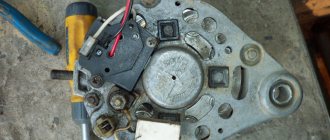
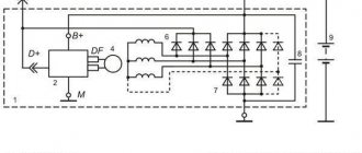
The design of an electromagnetic thermal relay is quite simple; it uses a circuit for connecting turn signals through an electromagnetic type relay. It is made in the form of a cylindrical core, and thin copper wire is used as winding. At the top of the core there are two groups of contacts, with metal armor installed on each side. The first group of contacts closes the circuit where there is a control light located on the instrument panel. With the help of other contacts, the circuit with the lights in the turn signals is closed. They are the ones who provide the flashing mode.
A thin nichrome rope is attached to the anchor of the main contact group. Move the armor away from the contact that is on the core. Therefore, the circuit will be open, which is normal. The core itself is installed on a special isolated platform, where the opposite end of the rope is also fixed. During operation, an electric current passes through the garland, since it, together with the resistor, is located in the switch. All elements of the device are enclosed in a cylindrical metal case.
The operating principle of an electromagnetic thermal relay is very simple. When the turn signal comes on, the circuit is closed. Under the influence of current, the nichrome string heats up and its length increases. The previously tensioned armature is attracted to the core, straightens and closes the contact in a short time. Because of this, crooked lamps begin to glow at full power. The current passes by the string, causing it to cool and contract again. As a result, the armature moves away from the core, which leads to the contacts opening. The lamps stop glowing, then the whole cycle resumes. The nichrome string heats up and cools down very quickly, so the lamps flash at an average frequency of 60–120 times per minute.
The blinking indicator light on the panel is also associated with the operation of the main group of contacts. Therefore, it works in sync with the headlights. Mini-sound signals in the form of characteristic clicks appear when the armature and contacts close and open, hitting each other.
A significant disadvantage of this device is the gradual stretching of the cable, which disrupts the normal operation of the relay. Therefore, these devices are now being replaced by more modern electronic relay designs.
Watch the video
Connecting a signal through a relay immediately solves many problems, the main one of which is electrolysis of wires due to unfavorable operating conditions of the vehicle (dirt, moisture).
Electronic relay: circuit and principle of operation
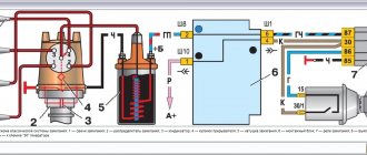
The design of the electronic rotation relay consists of two main parts. From a standard electromagnetic relay that performs switching to an electronic key that provides a certain frequency of operation of this device.
The nichrome cord has been replaced with an electronic key. With its help, voltage is applied and removed from the winding of the electromagnetic relay at certain intervals. The key is built on microcircuits or discrete elements. They are components of the main generator and control circuits.
The operating principle of an electronic relay is very simple. When voltage is applied to the relay, the master oscillator is activated. With its help, control pulses with different frequencies are generated, which enter the control circuit. With the help of pulses, the current flowing through the coil of the electromagnetic relay is supplied or interrupted. Such actions also cause the anchor to retract or sink. As a result, the contact groups close or open at a certain frequency, which gives the same blinking as indicator lights.
All electronic elements of the relay are mounted on a separate board. An electromagnetic relay is located above the board. Both are housed in a plastic case. The contacts are thrown out from below or to the side. There are holes and tabs for bolt connections to secure the housing.
Each electronic rotation relay has undeniable advantages over other designs. High-quality and technologically advanced devices manufactured on the basis of modern circuits and characterized by increased reliability have proven themselves. The technical characteristics of these devices remain unchanged regardless of their service life.
Order Yandex Taxi
Both schemes have a common drawback.
No one is safe from accidental short circuits during installation and operation!
Domestic relays of this series mark a normally closed contact as When the fastening parts melt, the contacts move and a sparking process is added, which further heats the contact point. If I made a mistake anywhere, please write and I will correct it.
The relay current is 30 A, it is possible to use and After applying a control signal to the relay, the first output will become open and the second closed. In this case, they should automatically turn off if the headlights are turned on.
Fill out the form, the answer will be sent by email
All powerful consumers of electricity in the car, such as headlights, starter, fuel pump, heated rear window, electric power steering, are connected through a relay. This circuit design solution has several disadvantages: the running lights remain on when the engine is turned off, which is contrary to current rules; the circuit will not work if LEDs are also installed in the dimensions; the circuit will not work correctly if the DRLs contain powerful SMD LEDs, the rated current of which is comparable to the current of a light bulb; For safety reasons, an additional fuse must be installed. When the voltage disappears, the armature returns to its normal state using a return spring.
When current is applied to the coil, magnetic field lines penetrate its core. How to connect a four-pin relay How to correctly connect a 4-pin relay. In the normal state, the first of the power terminals is closed, the second is open.
We only note that the most common: The relay is designed for switching large load currents. With this connection scheme, you supply voltage to the DRLs from the main power circuit of the car. In order for the DRLs to go off when the engine is stopped, you can send a signal to the button from the fuel pump, or from the same oil pressure sensor. Below you will find information from one manufacturer; there are other manufacturers and foreign analogues. how to connect a car relay (light ignition, etc.)
Source
Turn signal relay pinout
During operation, the standard turn signal relay may fail and in this case it must be replaced. Incorrect operation of the device becomes obvious, especially when the indicator lamp stops lighting. The main cause of the malfunction is incomplete closing of the device.
In other cases, the relay begins to work unstably; the relay contacts close at different intervals. In some cases, the volume level of the sound accompanying the operation of the device is significantly reduced. This can create a serious problem on the road when the device turns on without the driver noticing due to accidental impacts while driving.
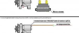
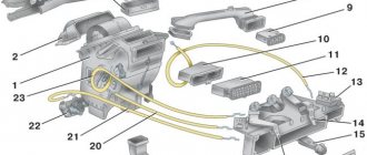
These shortcomings are eliminated by replacing the standard device with an electronic design. In this case, the turn relay is connected according to the standard diagram shown in the figure. Pin number 1 is positive, the second pin is used to connect to the rotation switch, the third is connected to the warning light, and the fourth is to ground.
All connections and contacts must be reliably insulated with electrical tape and cambric, which is a hollow plastic shell.
This eliminates possible short circuits with other conductors. Some disadvantages are created by the plastic housing of the electronic relay, which does not always fit into the normal position. However, home craftsmen quite easily overcome this difficulty and find the most optimal technical solution.
Opening the trunk using the car alarm key fob
If your car has an electric trunk drive, you can connect to it with a car alarm to open it using the alarm key fob. If the alarm outputs a low-current signal to open the trunk (and most often this is the case), then we use this circuit.
First of all, we find the wire to the trunk drive, where +12 Volt appears when the trunk is opened. Let's cut this wire. We hook up the end of the cut wire that goes to the drive to pin 30. We hook up the other end of the wire to pin 87A. We connect the alarm output to contact 86. We connect contacts 87 and 85 to +12 Volts.
Now, when a signal is sent from the alarm to open the trunk, the relay will work and “plus” will go to the trunk electric drive wire. The drive will operate and the trunk will open.
These are just a few wiring diagrams using relays. You can find a few more diagrams using relays on the website in the category trick diagrams and in the section diagrams for connecting to the central lock.
Source
DIY turn relay
Sometimes situations arise when the standard turn signal relay fails and a new device cannot be purchased. In such a situation, you can try to make a turn signal relay with your own hands to provide the car with the necessary signals. The simplest electronic devices that you can make yourself are simple and easy to use, operate smoothly and reliably. High precision is achieved through the use of PWM controllers used in all circuits.
The simplest replacement for an electromagnetic relay is designed for a maximum load power of 150 W. It is connected to the positive air gap. If the IRFZ44 field switch is replaced with the IRF3205 model, 200 W can also be connected. This simple circuit guarantees high accuracy. The blinking frequency does not depend on the power of the lamps, so LED, halogen and other lamps can be included in the circuit.
The blinking frequency is directly related to the capacitance of the capacitor. As the capacity increases, the indicator will blink less frequently, and conversely, decreasing the capacity will cause it to blink faster. The low-power 1n4148 diode can be replaced with any similar element. When the circuit reaches 80 W, a small amount of heat is observed in the FET area. This means it is ready to use.
There is another simple gear shift relay circuit with a coil - simple, reliable and inexpensive. It is capable of turning on both conventional and LED lamps and is designed for a voltage of 12 V. The contacts are connected according to the principle of a regular switch, that is, in series with the light bulb. The LED is installed in the circuit as an indicator during commissioning. The device parameters are regulated by changing the resistance of the resistor.
Engine lock
The blocked circuit can be anything, as long as the car does not start if the circuit is broken (starter, ignition, fuel pump, injector power, etc.).
We connect one coil power contact (let it be 85) to the alarm wire, on which a “minus” appears when arming. We apply +12 Volts to the other contact of the coil (let it be 86) when the ignition is turned on. Contacts 30 and 87A are connected to the break in the blocked circuit. Now, if you try to start the car with the security switched on, contact 30 will open with contact 87A and will not allow the engine to start.
This scheme is used if you have a “minus” from the alarm to blocking when arming. If you have a “minus” from the alarm to blocking when disarming, then instead of contact 87A we use contact 87, i.e. The open circuit will now be on pins 87 and 30. With this connection, the relay will always be in working condition (open) when the engine is running.
"Euroblock" VAZ 2106 (new model), diagram
Below is a picture of what the Eurobloc looks like in real life.
Photo of Euro block VAZ 2106
Below is the pinout of the new type of power supply or, as people say, “Euroblock”. The diagram also shows which fuse is responsible for what.
VAZ 2106 fuse block diagram with decoding
Legislation
Before practicing installing DRLs, I would like to dwell a little on the legal standards for installing DRLs, as well as the rules of their operation.
The very first and basic rule is that unauthorized installation of additional light signals on a car is prohibited. Yes, you are right, you do not have the right to install DRLs on your car if it was not equipped with them by the manufacturer. This will be considered as making changes to the design of the vehicle. For every change to a vehicle's design, a certificate must be obtained, which in itself is neither quick nor cheap. Otherwise, traffic police officers will issue you a fine, or even take your car to the impound lot.
How so? My neighbor installed DRLs on the Oka and drives calmly! - you ask. He is simply lucky to have loyal traffic police officers who do not pay attention to his DRL - I will answer you.
Once again, unauthorized installation of additional light signals on a car is prohibited if it was not equipped with them by the manufacturer. Therefore, you make any changes to the design of the vehicle at your own peril and risk. It’s a completely different matter if your car’s equipment does not include DRLs, but the more expensive trim levels of your model do have DRLs. In this case, you have the right to install DRL without any approval from the certifying authorities.
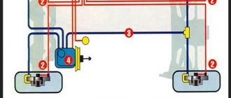
The first rule for installing DRLs concerns their location on the car body (see picture). If we briefly describe this figure, we get the following:
- DRLs should be installed at a height of 250 to 1500 mm;
- The distance between adjacent edges of the DRLs must be at least 600 mm;
- The distance from the outer side surface of the vehicle to the nearby edge of the DRL should be no more than 400 mm.
Now let’s briefly go through the rules of operation and use of DRLs:
- DRLs should only be used during daylight hours;
- It is prohibited to use DRLs in conjunction with side lights, low and high beam headlights, as well as fog lights.
Everything that is not prohibited is permitted. It's that simple. Separately, I would like to dwell on an important point, it concerns the use of DRLs in conjunction with high beam headlights. The rule goes something like this: When the high beam signal is briefly signaled, with the side lights and low beam headlights turned off, the DRLs should not turn off. Let me break it down: you are driving with your headlights and side lights turned off, your DRLs are on, when you signal with your high beams to an oncoming car that you are approaching a traffic police post, your DRLs should not turn off.
Just? I also think that there is nothing complicated here. Knowing the legislation and rules for using DRLs, we are ready to move on to the practice of connecting them. Let's start with the simple and incorrect and end with the complex and correct. Go!
Connection diagram for DRL from oil pressure sensor
In this part we will tell you how to connect the DRLs so that they turn on when the engine starts. To connect according to this scheme, you will need a 4-pin relay. The principle of operation of the circuit is approximately the same. In the normal state, relay contacts 30 and 87 are open, i.e. no current passes between them, DRLs are turned off.
As soon as you start the engine, the oil pressure indicator light on the dashboard goes out, a signal from the oil pressure sensor arrives at relay contact 86, this signal excites the coil in the relay, which controls the closure of contacts 30 and 87. After the closure of contacts 30 and 87, your DRLs turn on . This scheme is also not correct because your DRLs will always work as long as your car's engine is running.