The “sevens”, like most modern cars, use a single-wire circuit for supplying electricity to electrical equipment. The other terminal of the consumer is always connected to the ground of the machine to which the negative terminal of the battery is connected. This solution allows not only to simplify the design of the on-board network, but also to slow down corrosion.
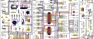
VAZ-2107 diagram: first option
Full size wiring diagram:
ELECTRICAL DIAGRAM OF VAZ 21074I CAR
Electrical connection diagram January 7.2 LADA 2107, ECM EURO-2 M7.9.7, 21074 with engines 2104, 2104-1411020-10, 21067, 21067-1411020-11, 12
Dashboard
Right mudguard wiring harness connections
Left mudguard wiring harness connections
Electrical diagram VAZ-2107 carburetor
Electrical diagram of VAZ 2107, 21074 produced in 1988-2001 with generator 37.3701
- block headlights
- side direction indicators
- accumulator battery
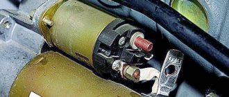
- starter relay
- carburetor electro-pneumatic valve
- carburetor microswitch
- generator 37.3701
- gearmotors for headlight cleaners *
- Fan motor switch sensor
- engine cooling fan motor
- sound signals
- distributor
- spark plug
- starter
- coolant temperature gauge sensor
- engine compartment lamp
- low oil pressure warning sensor
- low brake fluid level indicator sensor
- windshield wiper motor
- carburetor electro-pneumatic valve control unit
- ignition coil
- headlight washer pump motor *
- windshield washer pump motor
- mounting block
- windshield wiper relay
- hazard warning and direction indicator relay
- brake light switch
- reverse light switch
- ignition relay
- ignition switch
- three lever switch
- hazard switch
- socket for portable lamp**
- heater fan switch
- additional resistor for the electric motor of the heater (stove)
- rear window heating indicator lamp
- low brake fluid level warning lamp
- signaling unit
- heater fan electric motor
- glove compartment lamp
- light switches on the front door pillars
- switches for warning lights of open front doors ***
- front door open warning lights ***
- connection block
- cigarette lighter
- watch
- instrument light switch
- diode for checking the serviceability of the low brake fluid level indicator lamp
- fuel level indicator
- fuel reserve indicator lamp
- speedometer
- turn signal indicator lamp
- carburetor choke indicator lamp
- battery charge indicator lamp
- carburetor choke warning switch
- instrument cluster
- econometrician
- light switches on the rear door pillars
- coolant temperature gauge
- tachometer
- indicator lamp for parking brake activation (“handbrake”)
- low oil pressure warning lamp
- high beam indicator lamp
- indicator lamp for turning on external lighting
- voltmeter
- Parking brake indicator switch (“handbrake”)
- outdoor light switch
- rear window heating switch with backlight
- rear fog light switch with on/off indicator *
- fog light circuit fuse
- lampshade ****
- tail lights
- level indicator and fuel reserve sensor
- connectors for connecting to the rear window heating element *
- license plate lights 2107
Wiring diagram VAZ-2107 carburetor - full view:
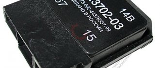
Types of breakers and their features
Modern rotary relays are mainly divided into two types: thermoelectromagnetic and electronic.
Each device has its own advantages and disadvantages, and this will be discussed. Thermal electromagnetic relays contain a core with two contact groups and side armatures. In addition, they have a copper wire winding. The contacts leading to the light bulbs are connected to a thin nichrome wire, which, in turn, is connected to a plate that is connected to the core. In the normal state, when no current flows into the circuit, the plate is not adjacent to its base. When the electrons begin to move, the nichrome wire heats up, elongates, and shorts the core plate. The lights come on. Afterwards, the nichrome cools down, the plate comes off again, the current changes direction, and the light bulbs burn at full intensity. Since the cooling-heating process occurs quite quickly, 1-2 times per second, the turn signals blink. Since the light bulb located on the instrument panel is also connected to the circuit, it also begins to pulsate. The specific clicking of the breaker is a consequence of the cyclic impacts of the armatures on the contacts.
Flashing car turn signals
A relay of this type was installed on all cars for quite a long time, but it had (and has) a significant drawback. Over time, the nichrome wire stretches and the turn signals no longer work. Besides this, there is another point. If one of the light bulbs burns out, the load on the others increases significantly. In recent years, thermoelectromagnetic relays are practically no longer installed on cars. They have been replaced by more reliable electronic breakers.
Electronic turn signal relays are built on the same principle as thermal ones, but instead of a nichrome wire, there is an electronic circuit made of transistors. The control chip contains an algorithm that produces automatic pulses that, at certain moments, supply current to the core winding. The operation of the device itself is as follows: after voltage is applied to the transistors, frequency pulses are sent from them, having the oscillations that are set by the program in the microcircuit. As the current passes through the circuit, it attracts the armature, closing the contacts leading to the lighting fixtures, causing the bulbs to light up. Since the cycle consists of signals of different frequencies, they either work at full intensity or dim.
Electronic turn signal relay
The advantage of electronic breakers is that they are more reliable than thermal ones. In addition, if one of the light bulbs in the circuit burns out, the others continue to work without unnecessary load. True, in some cars the circuit is designed in such a way that in this case the warning lamp on the instrument panel stops blinking. This is done specifically to additionally signal a malfunction. True, there are some disadvantages here too. First of all, such a relay creates radio interference and can affect the operation of many devices. The second negative factor is that the short circuit protection here is very weak, and at the slightest drop in electrical voltage the breaker can easily burn out.
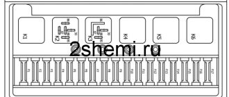
Mounting block connection diagram
P1 — relay for turning on the heated rear window; P2 - relay for turning on the headlight cleaners and washer; P3 - relay for turning on sound signals; P4 - relay for switching on the electric motor of the engine cooling system fan; P5 - headlight high beam relay; P6 - low beam headlight relay; A - the order of conditional numbering of plugs in the mounting block blocks. The outer number with the letter “Ш” in the plug designation is the block number, and the inner number is the conventional number of the plug.
What to do if the battery is boiling
The lamp goes out, the voltmeter needle goes to the right into the red sector, and there is a sharp “chemical” smell in the cabin. At idle, the needle is in the green sector, but as soon as you accelerate, it goes all the way to the right. This indicates that the voltage regulator (chocolate) has failed. If this happens, moving on is more expensive! All the electrical equipment of the car may burn out, and the battery will get damaged, the electrolyte will “boil”, the plates may become warped. To get to the repair site, you can temporarily turn off the generator by removing the wire from terminal “61” of the generator. You can drive for quite a long time on a good battery, just don’t forget to turn off unnecessary electrical appliances - heater fan, heated rear window, radio, etc. Headlights or running lights will have to be left.
Voltage too high (overcharge)
This article describes a simple way to determine if the alternator, voltage regulator, or connections between them are faulty. How to repair all this in the next article.
VAZ2105 stopped working, the right rear turn signal in front works. When you turn it on, the engine starts to heat up and the fuses light up. Tried the emergency lights, same situation. the left one works. what to do
Hello, my 2106 has lost turns, I turn on the emergency lights, they light up but don’t blink, tell me what could be wrong
Hello, please tell me I can’t find the reason. on the panel there is no sign of a light turning. But when you turn it on, it works and the emergency lights also work. The relay clicks and the light does not shine on the panel. How to find out the reason, thanks in advance.
Thank you)) helped me get home on a jig))
Hello Vyacheslav, I have a Niva 2121, produced in 1980, with an 8-pin emergency button. I want to install a 6-pin one, like you have on your car, how do I connect it correctly? Waiting for your answer please!
When my emergency lights are turned on, the instruments and turn signals do not work
You are simply a Super Master from God. You explain everything very clearly and clearly about this common problem. Tell me, have you tried to repair the steering column switch, is it repairable?
I have a VAZ 2107. The hazard warning lights and the left turn signal work, but the right one does not. What is the reason?
Good day. That's the problem. The turn signal lamp shines at a lower frequency in the high beam when the ignition is on. If you drive for a long time on the far one, the signal disappears, unless you switch to the near one and back. As soon as I turn the dimensions, the turn control blinks once. Help
thanks saved me time.
and here I am, the father of the girl who wrote to you about my problem with the turn signals on the VAZ 2103: the turns themselves work, but when I turn on the side lights or headlights, the turns light up constantly. What do you recommend doing in this situation?
Hello, my dad has a VAZ 2103 and the car has this problem: the turn signals work, but when you turn on the side lights or headlights, the turn signals glow with a constant light, which is not normal. Please tell me what needs to be done, otherwise our auto electricians don’t want to delve into old Lada cars. Thank you in advance.
Please tell me about this problem. VAZ-2107, when turning on the right turn or emergency lights, the turn relay heats up and the turn relay lights up, before that the fuse burned out. Left turn works fine. It's short somewhere, but I can't figure out where.
There is a fuse in the circuit there.
To help prevent all turns from turning and crashing, only the light bulb in the device does not shine, so you can tell it to work.
Schemes of individual blocks of the seven
Power supply system
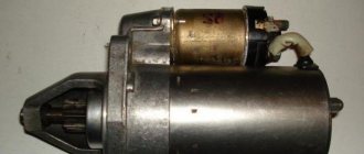
Power plant starting system
1 - starter; 2 - relay; 3 — ignition switch; 4 - battery
Ignition system
1 - generator; 2 — ignition switch; 3 - distributor; 4 - breaker; 5 — candles; 6 - coil; 7 - battery
Contactless ignition system
External and internal lighting
Windshield wipers and washers
1 — electric motors of the windshield wiper; 2 — washer motor; 3 — mounting block; 4 — ignition switch; 5 - washer switch
Cooling Fan
1 — fan electric motor; 2 - sensor; 3 — mounting block; 4 - ignition relay; 5 - ignition switch.
Symptoms of a faulty turn relay
Turn signals, as well as the relay that ensures their correct operation, make it possible to minimize the risks of
road traffic accidents when performing any maneuvers. That is why it is necessary to constantly maintain them in good condition and promptly eliminate any malfunctions.
The failure of the turn relay may be indicated by the following symptoms, which can actually be identified even without experience and diagnostic work:
- The turn signals do not blink, but stay on continuously. This indicates a breakdown of the electromagnet, which is stuck in one of two positions. Most likely, the relay may need to be replaced;
- The turn signal lamps flicker too quickly or, on the contrary, too slowly. This problem may be caused by incorrectly selected power of the light sources, however, it does not hurt to check the functionality of the relay;
- The turn signals don't work at all. It is quite possible that the cause of the breakdown is a burnt-out light bulb, a broken electrical contact, or a failed fuse. But if all these parts work normally, the problem lies in the turn relay.
Finding out that the device is not working is not difficult at all. If you do not hear characteristic clicks when you turn on the turn signals, then most likely the relay has failed and requires urgent replacement.
Wires for connecting electrical appliances
| Connection type | Section, mm2 | Insulation color |
| Negative terminal of the battery - vehicle ground (body, engine) | 16 | Black |
| Starter positive terminal - battery | 16 | Red |
| Positive contact of the generator - plus battery | 6 | Black |
| Generator - black connector | 6 | Black |
| Terminal on the generator “30” – white MB block | 4 | Pink |
| Starter connector “50” – starter relay | 4 | Red |
| Starter Start Relay - Black Connector | 4 | Brown |
| Ignition switch relay - black connector | 4 | Blue |
| Ignition switch output “50” – blue connector | 4 | Red |
| Ignition switch connector “30” – green connector | 4 | Pink |
| Right headlight plug - ground | 2,5 | Black |
| Left headlight plug - blue connector | 2,5 | Green, gray |
| Generator output “15” – yellow connector | 2,5 | Orange |
| Right headlight connector - ground | 2,5 | Black |
| Left headlight connector - white connector | 2,5 | Green |
| Radiator fan - ground | 2,5 | Black |
| Radiator Fan - Red Connector | 2,5 | Blue |
| Ignition switch output “30/1” – ignition switch relay | 2,5 | Brown |
| Ignition switch contact “15” – single-pin connector | 2,5 | Blue |
| Right headlight - black connector | 2,5 | Grey |
| Ignition switch connector “INT” – black connector | 2,5 | Black |
| Six-pin block of the steering column switch - “ground” | 2,5 | Black |
| Two-pin block of the steering column switch - glove box illumination lamp | 1,5 | Black |
| Glove compartment light - cigarette lighter | 1,5 | Black |
| Cigarette lighter - blue block connector | 1,5 | Blue, red |
| Rear window defroster - white connector | 1,5 | Grey |
Useful: Lada Vesta VAZ-2180 diagram
Turn signals on VAZ do not work
Ignition switch VAZ 2107: connection diagram, replacement, how to remove, instructions with photos and videos
During the operation of the vehicle, malfunctions associated with electrical equipment may appear. One of these troubles is the failure of the turn signal system, usually associated with the indicator relay. We will try to look at what the turn signal system consists of, the most common faults and answer the question of what to do if the turn signals do not work.
Turn signals are a key part of road safety.
Their use lets drivers know your intentions so they can make appropriate decisions and maneuver wisely. The first turn signals appeared in the form of special arrows, activated by a special mechanism and indicating the direction of movement of the car. After that, the system was improved and instead of primitive signs and indicators, the first lamps appeared, which made the driver’s work easier and distracted him less from driving. Those turn signals that we are used to seeing appeared in the 30s of the last century and were used in the form of special lamps located on the wings or bumper of a car. Over time, this has become an essential component of any car and its serviceability must be fully maintained.
Direction indicator connection diagram
Before talking about turn signal malfunctions, you need to know what the turn signal circuit consists of. It includes light bulbs, turn signal relay, switch, fuse and hazard warning button.
A relay is a switching element in an electrical circuit. It is this that ensures that the lamps are switched on and off briefly while the turn signals are operating. The relay receives information about the closure of the circuit of one side or another of the indicators from the turn switch and the hazard warning button.
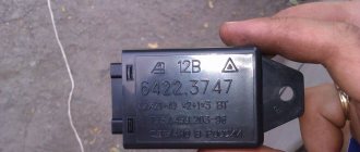
Accordingly, it closes the desired circuit and ensures the operation of specific light bulbs. The location of the relay may vary. On new cars it is placed in the mounting block, and, for example, on Zhiguli cars it is installed behind the instrument panel. There it is secured with a special ring screwed to the car body with a nut. This ring acts as a “mass” and must always be cleaned. Also, the turn signal relay can be attached to the side member of the car.
Lamps are the main element and play the role of that very pointer. The switching on of the lamps is ensured by the direction of the signals coming out of the relay. The connection diagram of the lamps is ensured in such a way that even if one of them burns out, this will not affect the operation of the others.
The turn signal switch is located on the steering column of the car and serves as a control device for the driver. Using the switch, you can set the direction in which the direction indicators are turned on.
Hazard warning button - ensures that all the lights included in the turn signals are turned on. At the contact group of the button, all wires are connected, including the ignition switch wires.
All elements of the circuit are connected using electrical wiring and the car body (or in popular parlance - “grounds”).
The fuse is designed to protect the circuit from short circuits. This can happen if you accidentally short-circuit the wires that are part of the circuit or because their insulation is insufficient. The fuse has a fuse link, which, when the current in the circuit increases (accompanied by an increase in the temperature of the conductors), breaks the electrical circuit and protects the circuit from fire.
The nature of malfunctions of VAZ turn signals
Knowing all the components of the circuit, you can begin troubleshooting. To begin with, it is worth understanding that if the turn signals suddenly stop working, first of all, check the corresponding fuse. To find out where it is located, look at its cover (usually there are symbols located there) or find the symbol in the technical literature of the car. Before carrying out repair and diagnostic work, be sure to disconnect the negative terminal of the battery.
Car wiring diagram
1 – radiator fan drive motor; 2 – relay and fuse block (mounting block); idle speed sensor; 4 – engine control unit; 5 – potentiometer; 6 – set of spark plugs; 7 – ignition control unit; 8 – electronic crankshaft sensor; 9 – electric fuel pump; 10 – tachometer 2107; 11 – lamp for monitoring the health of electronic systems; 12 – ignition system control relay; 13 – speed sensor; 14 – diagnostic connector; 15 – set of injectors; 16 – adsorber solenoid valve; 17, 18, 19 – fuse block protecting the injection system circuits; 21 – electronic fuel pump control relay; 22 – electronic relay for controlling the intake pipe heating system; 23 – intake pipe heating system; 24 – fuse protecting the heater circuit; 25 – electronic oxygen level sensor; 26 – cooling system temperature control sensor; 27 – electronic air damper sensor; 28 – air temperature sensor; 29 – pressure control sensor.
Frequent malfunctions of turn signals and emergency lights, and how to fix them
If the turning lights stop working, you need to carry out diagnostics and try to eliminate the identified faults. When you can’t do it yourself, you should contact a car service.
Turn switch
To identify such a breakdown, check the functionality of the contacts when the switch is in different positions. Inspect plastic or metal elements. In this case, melting or carbon deposits may appear. Then the relay clicks, but neither the right nor left turning mechanisms work.
To eliminate the breakdown, the switch is removed and disassembled. After cleaning the contacts, the part is assembled in the reverse order. A photo taken in advance will make the job easier.
Turns relay
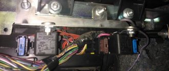
A faulty element requires immediate repair. The part is inexpensive, so they buy 2 pieces in reserve. The relay is located in the fuse box in the engine compartment or inside the passenger compartment. The operating instructions help determine the location of the part you are looking for. The mounting block contains an image describing the purpose of the switches and relays.
Faulty lamp blade wiring
Finding the location of the wiring break is made difficult by the fact that the turn signals are connected to the rear parking lights. The cables run throughout the entire cabin, and the lamps are installed on the tailgate.
- under the thresholds in the area of the front passenger and driver's seats;
- in the adapter that supplies wiring to the trunk lid;
- in the headlight sockets.
If the left or right turn signal is faulty, you should check the contacts of the light bulbs with a multimeter. If voltage is present, tighten the lamellas of the socket into which the base is inserted. Modern manufacturers supply cars with LED elements.
Hazard switch
If this part breaks, the lamps start on both sides simultaneously. On some cars, the rotary control relay is located in the hazard warning light switch. A new button is inexpensive, so it is recommended not to repair it, but to replace it.
Malfunction or software failure of the body control unit
In some models, such as the Lada Priora, the functions of switching the indicators in question are transferred to the body control unit. The advantage is the possibility of centralized control, the disadvantage is the complication of auto repair. To eliminate the breakdown, disassembling the unit is required. Such repairs are performed only in a car service center.
Blown fuses
Fusible parts responsible for the operation of turning or emergency lights rarely burn out. If this does happen, check the integrity of the wiring, the condition of the lamp contacts, and replace the fuse if necessary.
Fuse and relay diagram 2107
On newer “sevens” a block with 17 fuses and 6 relays is installed. VAZ 2107 fuses on the “new” unit protect the following electrical circuits and devices:
- Reversing lamps, heater fan, rear window defroster warning lamp and relay, rear wiper motor and rear washer pump.
- Electric motor for front wipers.
- Reserve socket.
- Reserve socket.
- Power supply for heated rear window.
- Clock, cigarette lighter, power socket “carrying”.
- Signal and radiator fan.
- Turn signal lamps in emergency mode.
- “Fog lights” and a relay that regulates the voltage of the on-board network.
- Instrument panel lamps.
- Brake light bulbs.
- Right high beam headlight.
- Left high beam headlight, high beam warning lamp.
- Side lights (rear right, front left), license plate and engine compartment lighting.
- Side lights (rear left, front right), glove compartment and cigarette lighter lamps.
- Low beam (right lamp).
- Low beam (left lamp).
The block relays perform the following functions:
- Heated rear window relay.
- Headlight cleaner and washer relay.
- Signal relay.
- Cooling system electric fan relay.
- High beam relay.
- Low beam relay.
The fuse block of the VAZ 2107 (injector) is no different from the block on the carburetor “seven”. Injection models are simply equipped with an additional relay and fuse box installed in the cabin under the glove compartment. The block includes three relays - the “main” relay, the fuel pump relay and the fan relay.
Self-diagnosis of car lighting devices
Connection diagram for generator 2107 to 2106
There are several situations in which it can be determined that the optics need diagnostics:
- The turns do not flash, but light up. Such a malfunction indicates the failure of the relay, in particular, we are talking about its electromagnetic component. The electromagnet itself could close in one of the positions, as a result of which it cannot return to its initial state.
- The turning lights flash very quickly or very slowly. In this case, the problem may lie not only in the relay. In some cases, this type of malfunction occurs when the driver uses inappropriate lighting sources. So when purchasing new light bulbs, you need to make sure that they correspond to the rating set by the car manufacturer.
- The optics don't work at all. That is, the turning light bulbs do not flicker, and the corresponding indicators on the dashboard also do not light up. In addition, there are no characteristic clicks that appear when turning on the turning lights. With such symptoms, there can be many reasons for the problem; we will tell you more about their diagnosis below (the author of the video is the Steel Horse channel).
As for diagnostics, it is performed in several stages:
- First of all, you need to make sure that all sensors and indicators on the device are working. If they do not function, then it is necessary to diagnose the safety devices.
- If all devices are operating in normal mode, then you next need to turn on the light alarm button and diagnose all light sources in the headlights. That is, check the front, rear, and side (if any) lights.
- If the alarm does not function when activated, you need to check the functionality of the relay, and also check the power supply at the terminals. To do this, remove the relay from its mounting location, and then, using a test light, connect one of its contacts to the installation site (to the positive), and the other to the car body or battery. There is no need to turn on the ignition. If there is no power, then most likely the reason lies in a failed safety device, a broken hazard warning button, or a damaged electrical circuit. Also, the essence of the problem may lie in poor contact in the connecting plugs.
- If there is a plus on the contacts, then try shorting the two relay terminals using copper wiring. If all electrical circuits, as well as the connection plugs, are working properly, then all turn signals should light up. In this case, the fault must be looked for in the relay.
- If the lights do not light up after the steps you have performed, then most likely the cause of the malfunction lies in the emergency light control button. However, in practice this happens quite rarely; there is often a short circuit in the circuit. By the way, it is a short circuit that can lead to a breakdown of the relay, therefore, before replacing the failed element, you need to eliminate the short circuit.
- If the emergency signal is functioning, this indicates that the safety devices and relays are working; accordingly, you need to start diagnosing the button itself. First of all, you need to diagnose the positive terminal, as in the case of checking the relay, while the ignition, as well as the hazard warning button, must be activated. If the diagnostics showed that there is no plus, this indicates that the button itself needs to be checked in more detail. Remove it from its seat and check the connection circuit. If there is no power, then you need to look for a break in the wiring from the tidy to the button itself. If there is power, then it will be necessary to short-circuit the terminals at the installation site, the ignition does not turn off, after which the direction indicators must be activated (on either side). When the lighting sources are turned on, the control button must be replaced, but if there is no power, then you need to check the power in the emergency relay. If there is no power, the problem most likely lies in a break in the connecting electrical circuit from the control key to the block with safety devices.
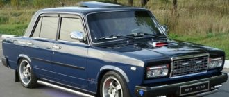
Modifications of the VAZ-2107 car
VAZ-2107 . Basic version of the sedan, with an 8-valve carburetor VAZ-2103 engine, 1.5 liters.
VAZ-2107-20 . The same VAZ-2107, but with a 1.5-liter VAZ-2104 injection engine that meets the Euro-2 environmental standard.
VAZ-2107-71 . The car for the Chinese market was equipped with a VAZ-21034 engine, with a volume of 1.4 liters and a power of 66 horsepower, specially tuned for A-76 gasoline. The pistons were taken from a VAZ-2108.
VAZ-21070 . Modification of a car with an 8-valve, carburetor VAZ-2103 engine, volume 1.5 liters.
VAZ-21072 . Modification with an 8-valve carburetor VAZ-2105 engine, volume 1.3 liters.
VAZ-21073 . An export modification for the European market, which was equipped with a 1.7-liter injection engine with a capacity of 84 horsepower. The engine of this car had a catalytic converter that satisfied environmental protection requirements.
VAZ-21074 . Modification with an 8-valve, carburetor VAZ-2106 engine, volume 1.6 liters.
VAZ-21074-20 . Modification with a 1.6-liter VAZ-21067-10 injection engine, which complies with the Euro-2 environmental standard
VAZ-21074-30 . Like the previous model, but with a VAZ-21067-20 engine, which meets the Euro-3 environmental standard
VAZ-210740 . Modification produced in 2010, equipped with a VAZ-21067 injection engine with a catalyst. Engine capacity is 1.6 liters, power is 72.7 horsepower.
VAZ-21076 . Export modification with a VAZ-2103 carburetor engine.
VAZ-21077 . Export modification with right-hand drive for the UK market. The car was equipped with a VAZ-2105 carburetor engine with a volume of 1.3 liters.
VAZ-21078 . Another export modification for the UK, but with a 1.6-liter VAZ-2106 carburetor engine
VAZ-121079 . The modification, developed specifically for the needs of the Ministry of Internal Affairs and the KGB, was equipped with a powerful VAZ-413 rotary piston engine with a volume of 1.3 liters and a power of 140 horsepower.
VAZ-2107 ZNG . The car is equipped with an 8-valve, fuel-injected VAZ-21213 engine with a volume of 1.7 liters.
PURPOSE OF TURN RELAY
The device is used to ensure that the front and rear turn lamps and repeaters blink when turned on. Another function performed by this device is an alarm. All the cornering lights around the perimeter of the car are flashing. When the relay operates, it produces a click-type sound signal that is clearly audible and lets the driver know that the turn signal or hazard warning lights are on.
Volzhsky Auto used two types of breakers:
- Electromagnetic.
- Semiconductor.
The electromagnetic type of breaker was installed on the first models of the plant’s automobile line, and only with the VAZ 2106 they began to install the second type of device. The circuit is entirely assembled on semiconductors, however, the main function of interrupting contacts is performed by an electromagnetic coil. The operating frequency is controlled using a microcircuit (pulse generator).