With such a colossally high rhythm of movement, the behavior of each individual motorist in traffic should be as predictable and understandable as possible to others. What is important here is not only the ability to drive a car and give the necessary signals on time, but also the technical serviceability of the light signaling systems. This is especially felt when driving old-style cars, for example, a VAZ 2106, whose direction indicators, low and high beams operate using relays. This equipment has long been discontinued and is potentially problematic, which means its owner is simply obliged to know the structure and methods of repairing the systems of his car.
Design and operation of the turn relay
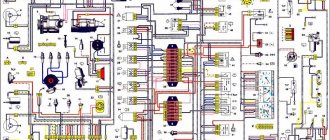
The standard turn signal relay of the VAZ 2106, the price of which is a small amount and is quite affordable for any Russian car enthusiast, is a mandatory means of warning about changes in movement for a vehicle due to the signal system adopted among motorists and is located under the instrument panel in the area of the driver's seat. The direct electrical circuit of the “six” turn relay and its position in the vehicle’s electrical system is located below
and the numbering in the figure is deciphered as follows:
- Sidelights "six".
- Side direction indicators.
- Battery
- Generator device.
- Egnition lock.
- A block device for the concentration of safety elements that protect all electrical circuits of the vehicle’s power equipment.
- Relay for VAZ 2106 direction indicators and emergency signaling, operating in intermittent mode.
- Turn signal indicator light located in the speed sensor (speedometer).
- Button to stop the flashing of the emergency lights.
- Stern optics.
- Rotary switch element in a three-position switch.
Malfunctions of turn signals VAZ 2107
The main symptom of a malfunction is non-functioning direction indicators. However, the reason may not be only the relay. There are several possible breakdowns:
- The turn signal lamps are constantly on and do not blink. This indicates a malfunction of the electromagnetic part of the VAZ 2107 turn signal relay - the contacts are stuck in the closed position and do not open. This could be either a burnt-out contact of the electromagnetic relay or a failure of the electronic circuit of the turn relay. Regardless of the specific reason, there is only one way out - replacing the VAZ 2107 turn signal relay.
- Lights flash too slowly or quickly. The reason may be either in the electronic part of the turn relay or in the discrepancy between the current consumption of the lamps and the nominal one. If one of the lamps has burned out or lamps that consume less current are installed, the turns will flash more often than necessary. The same phenomenon occurs if the wire going to one of the lamps is broken, or the lamp socket or base is oxidized. A similar phenomenon occurs when installing LED lamps instead of incandescent lamps. When installing more powerful lamps, the blinking frequency decreases. If all the lamps are in working order and the malfunction did not appear after replacing the lamps, the reason lies precisely in the turn relay or poor contacts in the lamp power circuit.
- The direction indicator lamps do not light up. The cause of the malfunction may be a broken turn switch, a burnt-out (faulty) turn relay, an open circuit, or a blown fuse. It is better to start checking from the last one
Replacing the turn relay
The necessary replacement of the VAZ 2106 turn relay begins with preparing the workplace for such a technological operation. This requires:
- Release the instrument panel from the clamps using a screwdriver with a thin blade or an awl.
- Then we press out the spacer clamps at the installation sites and pull out the instrument cluster inside the cabin.
- We disconnect the wire blocks, having previously marked them with a marker or paint.
- Unscrew the speed sensor cable.
- We connect the wire with blue insulation to the third connector of the updated product, which is the contact of the warning lamp on the instrument cluster.
- We screw a free section of wire to the fourth connector of the updated product, which we then connect to “ground” (the place where the new “relay” is attached).
- We connect a wire with white-black insulation (in some models - with a purple braid) and the second connector of the turn relay, as well as with the seventh connector, which goes to the alarm button (numbers are indicated on the back of the part).
- We connect the orange braided wire with the number 4 to contact No. 2 of the shutdown button.
- We connect the first output contact of the VAZ 2106 turn signal relay to contact No. 4 of the emergency starter.
- The eighth connector of the emergency starter is powered with contact 1 of the fuse.
- We connect the first connector of the emergency starter to the blue braided wire.
- And we connect the third output contact of the “emergency light” to a wire in a black and blue braid.
This replacement of the turn relay is carried out due to the frequent failure of the standard product. During the operation of a standard turn relay, there comes a time when it periodically begins to work incorrectly. This can be noticed by the absence of fire in the “control”. The reason is the lack of complete closure of the product. The absence of sound accompaniment for the turning maneuver creates the illusion that the turn signal relay is faulty.
In another case, a product malfunction manifests itself in an unstable period of product functionality. This is due to the time interval for closing the relay contacts. The next thing is that the standard turn signal relay operates at a low volume level, which creates a problem if it is switched on without permission due to accidental contact while driving the car.
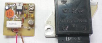
The above shortcomings can be eliminated by replacing the turn relay from a standard one to an electronic one. The pinout of the electronic type relay is shown below
- Positive contact.
- Output contact to the turn signal switch.
- "Control".
- "Weight".
It is necessary to remember that good insulation of contacts is required, and this must be done using insulating tape and cambric (hollow plastic braiding). This is necessary to eliminate possible short circuits with other wiring. Another feature is that the VAZ 2106 electronic-type turn signal relay is integrated into a plastic housing and its linear dimensions do not make it possible to install it in a standard position. In addition, the presence of an additional “petal” also interferes with the installation process.
An independent solution is required to connect a new type of turn relay. We suggest using the so-called as an alternative. “strip” is a plastic type tightening clamp for fastening electrical wiring. This fastening seems to be quite long-term and reliable.
With such a colossally high rhythm of movement, the behavior of each individual motorist in traffic should be as predictable and understandable as possible to others. What is important here is not only the ability to drive a car and give the necessary signals on time, but also the technical serviceability of the light signaling systems. This is especially felt when driving old-style cars, for example, a VAZ 2106, whose direction indicators, low and high beams operate using relays. This equipment has long been discontinued and is potentially problematic, which means its owner is simply obliged to know the structure and methods of repairing the systems of his car.
Malfunctions of turn signals VAZ 2107
The main symptom of a malfunction is non-functioning direction indicators. However, the reason may not be only the relay. There are several possible breakdowns:
- The turn signal lamps are constantly on and do not blink. This indicates a malfunction of the electromagnetic part of the VAZ 2107 turn signal relay - the contacts are stuck in the closed position and do not open. This could be either a burnt-out contact of the electromagnetic relay or a failure of the electronic circuit of the turn relay. Regardless of the specific reason, there is only one way out - replacing the VAZ 2107 turn signal relay.
- Lights flash too slowly or quickly. The reason may be either in the electronic part of the turn relay or in the discrepancy between the current consumption of the lamps and the nominal one. If one of the lamps has burned out or lamps that consume less current are installed, the turns will flash more often than necessary. The same phenomenon occurs if the wire going to one of the lamps is broken, or the lamp socket or base is oxidized. A similar phenomenon occurs when installing LED lamps instead of incandescent lamps. When installing more powerful lamps, the blinking frequency decreases. If all the lamps are in working order and the malfunction did not appear after replacing the lamps, the reason lies precisely in the turn relay or poor contacts in the lamp power circuit.
- The direction indicator lamps do not light up. The cause of the malfunction may be a broken turn switch, a burnt-out (faulty) turn relay, an open circuit, or a blown fuse. It is better to start checking from the last one
VAZ2105 stopped working, the right rear turn signal in front works. When you turn it on, the engine starts to heat up and the fuses light up. Tried the emergency lights, same situation. the left one works. what to do
Hello, my 2106 has lost turns, I turn on the emergency lights, they light up but don’t blink, tell me what could be wrong
Hello, please tell me I can’t find the reason. on the panel there is no sign of a light turning. But when you turn it on, it works and the emergency lights also work. The relay clicks and the light does not shine on the panel. How to find out the reason, thanks in advance.
Thank you)) helped me get home on a jig))
Hello Vyacheslav, I have a Niva 2121, produced in 1980, with an 8-pin emergency button. I want to install a 6-pin one, like you have on your car, how do I connect it correctly? Waiting for your answer please!
When my emergency lights are turned on, the instruments and turn signals do not work
You are simply a Super Master from God. You explain everything very clearly and clearly about this common problem. Tell me, have you tried to repair the steering column switch, is it repairable?
I have a VAZ 2107. The hazard warning lights and the left turn signal work, but the right one does not. What is the reason?
Good day. That's the problem. The turn signal lamp shines at a lower frequency in the high beam when the ignition is on. If you drive for a long time on the far one, the signal disappears, unless you switch to the near one and back. As soon as I turn the dimensions, the turn control blinks once. Help
thanks saved me time.
and here I am, the father of the girl who wrote to you about my problem with the turn signals on the VAZ 2103: the turns themselves work, but when I turn on the side lights or headlights, the turns light up constantly. What do you recommend doing in this situation?
Hello, my dad has a VAZ 2103 and the car has this problem: the turn signals work, but when you turn on the side lights or headlights, the turn signals glow with a constant light, which is not normal. Please tell me what needs to be done, otherwise our auto electricians don’t want to delve into old Lada cars. Thank you in advance.
Please tell me about this problem. VAZ-2107, when turning on the right turn or emergency lights, the turn relay heats up and the turn relay lights up, before that the fuse burned out. Left turn works fine. It's short somewhere, but I can't figure out where.
There is a fuse in the circuit there.
To help prevent all turns from turning and crashing, only the light bulb in the device does not shine, so you can tell it to work.
Keys in the scheme
If you turn to the Road Traffic Rules (TRAF) in force on the territory of the Russian Federation, there are clear formulations regarding maneuvering. Before starting to move, changing lanes, changing direction, or stopping, the driver of a VAZ 2106 is required to use direction indicators, and if they malfunction, give a signal with their hands. In conditions of poor visibility, it will also be necessary to use low beam sources, and to increase the information content of the dialogue between traffic participants, also high beam ones.
The switched-on lighting is usually enough to make the car visible on the road, but no more. If you need to draw the attention of other traffic participants to a specific detail, the action, lighting should not be static, but dynamic - flashing. To put this principle into practice, you need to understand that both the headlights and indicators are part of a single electrical circuit of the “six”. In order for the indicators to blink, a periodic break in the power supply circuit of the lamps is required, and this is where a special remote key or relay is needed.
In the “six”, most of the relay breakers are located in a compact, single unit in the power compartment. At the same time, the electronic key for the turn signals and emergency lights are located inside the cabin under the dashboard. Externally and technically they are of the same type, that is, there should be no problems with interchangeability. The main tasks of these circuit components are:
- power supply for lighting lamps and direction indicators;
- periodic interruption of the circuit, creating the effect of blinking lights;
- a sound signal in the form of characteristic clicks accompanying interruptions and blinking.
Performing all the necessary functions is possible thanks to the design of the relay itself, which has two groups of contacts. Some are stationary, while others are movable, connected to an armature, and through it to an electromagnetic coil. When the latter attracts the contacts, they hit the anchors, causing characteristic clicks.
Work principles
The variety of turn relays is quite large, but they are all divided into two main types:
- classical electromagnetic-thermal relays;
- electronic relays.
Electromagnetic-thermal relays are considered obsolete and can now only be found on very old cars, for example, classic Zhiguli cars. This type of relay consists of a core with a copper winding. There are two contact groups in the upper part of the core, and metal anchors in the sides. The structure is placed in a metal case, in the lower part of which contacts for connecting to the network are output.
When the turn switch is turned on, the network is closed - the lamp does not light. Then one of the anchors, under the influence of the nichrome string in the core, straightens and closes the contacts. After this, the current begins to flow in a bypass circuit, and the lamp lights up at full power. The click of the turn signals is ensured by the impact of a metal armature on the contacts.
An electronic relay consists of two main parts: a classic electromagnetic relay and an electronic key that ensures the frequency of operation of the relay. In a relay of this type, the operating principle of the nichrome string, which ensures the closure of the contacts, is assigned to a separate circuit board (key). Otherwise, the operation scheme is similar: the flowing current closes the contacts, after which the indicator lamps and the light on the dashboard light up. Interruption of the current leads to lowering of the armature and opening of the contacts - the indicator lamps go out. A characteristic click is also provided by the impact of the armature on the contacts.
Breaker relay malfunctions
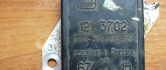
Malfunctions in the operation of the turn signal or low/high beam relays in the VAZ 2106 are quite rare. These mechanisms are quite reliable, but, being part of the overall electrical circuit of the car, they are not immune to problems such as overvoltage, breakdown, etc. In fact, the products are non-repairable - it is almost impossible to eliminate damage to the coil or contacts qualitatively. In other words, if a defect or malfunction is detected, the mechanisms are simply replaced with similar ones, selecting them by catalog number:
- for the turn signal relay - 231.3747-10(11) or 23.3747-10(11);
- for the lighting breaker relay - 113.3747-10(11) or 90.3747-10(11).
The number at the end of the designation indicates the design of the device case: the 10th modification is equipped with a mounting flange, while the 11th version does not have it, which is compensated by the increased dimensions of the case. Also, when choosing electronic relay breakers, you should remember that rotary models are compatible with alarm relay units, and lighting ones are compatible with devices for switching on the fan motor, horn, and rear window defroster. A malfunction of the relay unit may be indicated by problems in the operation of the light bulbs controlled by it due to the impossibility of closing the circuit or, conversely, opening it.
For rotary relays, typical signs of a malfunction may include flashing too fast or too slow, or no clicks. But the rapid blinking of the control light on the dashboard indicates that the lamp in the headlight has burned out, and not the relay itself.
conclusions
Of course, in order to carry out a proper connection or upgrade, you need to know where your car's turn signal relay is located. In most models it is mounted in the fuse box. But some manufacturers put it behind the dashboard, even in the steering column. Therefore, before starting all work, make sure that you know what you are doing, study the electrical and wiring diagrams so as not to make mistakes.
Recently, LED automobile lamps have become used. They are more durable and consume less current. The latter precisely affects the operation of the turn relay, changing its frequency. The frequency of relay operation is tied to the load resistance, that is, to the installed lamps. As the load resistance increases, which is exactly what happens when one of the lamps burns out or opens, the relay begins to operate most often. The same effect is observed when installing LEDs in direction indicators, since their power consumption is less, which means the resistance is much greater.
After studying the material in this article, you will be able to modify the standard turn signal relay for LEDs so that it operates at the frequency you need.
First of all, a little about the standard relay. The 3-pin turn signal relay which will be discussed is installed on cars starting from VAZ 2108 to the present, that is, on VAZ 2109, 2110, 2111, 2112, Lada Priora, Lada Kalina, GAZ cars. Marking 495.3747-ХХ.
To modify the relay, it will be necessary to open the housing. To do this, take a flat-blade screwdriver and remove the housing cover by pulling the plastic latches from two opposite sides.
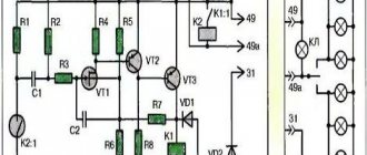
Now let’s figure out what is responsible for what in this circuit and how we can change the operation so that with increased load the frequency of operation of the direction indicators does not change. The first is connection. Ground is connected to pin 31. 49a - output to lamps, 49 - input “+” from the turn signal switch.
R3 is a current-limiting resistor to the control base of the transistor in the microcircuit; R1 and C11 - these are the radio elements that are responsible for the frequency of the output signal from pin 3 of the microcircuit. From leg 3 power is supplied to the relay winding; Conclusion 7 is also an interesting conclusion. The output controls the change in resistance and, accordingly, voltage at contact 49 a. It is he who gives the command to the microcircuit to change the frequency when the lamps burn out. The microcircuits can be not only those indicated on the diagram, but also, for example, KR1055GP1B, etc. analogues.
Now, presenting the functional purpose of the relay elements, it is not difficult to decide on measures to maintain the frequency of operation of the direction indicators when their internal resistance changes, that is, for example, when installing LEDs.
It is possible to change the capacitance value, double it (replacing it with a 4.7 µF capacitor instead of 2.2 µF - in the photo the capacitance is increased due to parallel connection of an additional capacitor to the standard one), but in this case the alarm system does not work correctly.
It will operate at half the frequency. The option of changing the resistance is also not entirely successful. Since, in fact, here you will have to empirically select a current-limiting resistor at pin 4, which is also not a very good option.
Turning relay switching diagram 495.3747
There remains the last and perhaps the best way out. In fact, remove control over load resistance. By cutting the foil on the printed circuit board (red line) going to pin 7 of the microcircuit, we will get a stable frequency response of the direction indicators.
After this modification, resistor R2 must be reduced to 60 - 200 Ohms.
The only drawback of this modification of the relay for LEDs will be the lack of monitoring of burnt-out LEDs, since we have actually removed the dependence of frequency on load resistance.
Turn signals play an important role in road safety, and their failure can lead to a lot of trouble. A small device - a turn relay - is responsible for the operation of the turn signals. Read about what types of turn relays are used in VAZ cars, how they are designed and work, as well as about their malfunctions and repairs in this article.
Replacing relay units
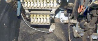
Since the turn signal relays on the VAZ 2106 are located under the dashboard, the first step in the process of replacing them is to dismantle it. To do this, press the panel clamps, and then the clamps along the contour. The block is pulled out inside the cabin.
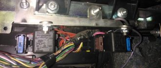
The turn signal relay unit is screwed with a nut to the engine compartment housing. To dismantle it, you will first have to unscrew it using a 10mm socket wrench. The nut presses against the terminals of the two ground wires, which it is advisable to mark to avoid confusion in the future. The removed relay block is disconnected from the terminal block, after which the assembly process takes place in the reverse order: connecting the new block to the block, and then the ground wires, screwing it to the body and installing the dashboard.
Relay keys for headlights are located in the engine compartment itself, on the right mudguard. First you will have to dismantle them by unscrewing the mounting screws. Please note that under the mounting bracket of the unit attached to the high beam, there is another contact of the ground wire.
After dismantling the lighting relay unit, the power wires are disconnected. It is strongly recommended to mark them so as not to confuse them during reassembly. You can do without this operation by immediately connecting the disconnected contacts to a new relay unit. After this, the mechanisms are installed and fastened into place.
VAZ-2106 is also known under the names “Zhiguli-1600”/“Lada-1600”. Years of production: 1976, 1977, 1978, 1979, 1980, 1981, 1982, 1983, 1984, 1985, 1986, 1987, 1988, 1989, 1990, 1991, 1992, 1993, 1994, 1995, 1996, 1997, 1998, 1999 , 2000, 2001, 2002, 2003, 2004, 2005 and 2006. In this article you will find a description of fuses and relays of the VAZ 2106 with a block diagram. Let's highlight the fuse responsible for the cigarette lighter.
p, blockquote 1,0,0,0,0 —>
p, blockquote 2,0,0,0,0 —>
Why turn signals don't work - reasons for turn signal failure
Motorists often encounter such a problem as a non-working turn signal, but not every one of them knows how to quickly solve the problem. Continuing to drive if such a breakdown occurs is very dangerous. It is better to stop and try to fix the problem.
Types of problems and troubleshooting methods
The turn signal works correctly if the following indicators are met:
- the presence of the ignition on ensures the operating mode;
- moving the steering column switch up and down must be accompanied by turning on the turn signal on the corresponding side;
- The turn signal should flash at a rate of 60 cycles per minute.
Flashing at a certain frequency
Any other turn signal behavior indicates a problem. The most common causes of malfunctions include:
Non-blinking turn signal. The problem requires familiarity with the basic principle of relay operation: the current passing through the lamps leads to heating of the measuring resistor - an element that determines whether a particular lamp needs to be turned on. Consequently, the lamp resistance, different from the nominal one, changes the time the turn signal is turned on: it begins to blink. In this situation, it is recommended to lightly tap the relay (this helps if there is a weak connection or moisture). If you have replaced the relay, but the turn signal does not blink, but is constantly on, then there is poor contact with the fuse block. Replacing a fuse that was found to have a resistance value that does not correspond to the nominal value can also help.
Turn signal light
Stopping the operation of one turn signal is incompatible with a relay malfunction (problems of this type cause the operation of both turn signals to malfunction). One of the turn signals may fail due to a burnt-out light bulb (the simplest option) or a faulty wiring or socket. The new tab must not only fit into the turn signal socket, but also correspond to the power indicated on the lamp
If after replacing the light bulb the turn signal still does not start working, you need to pay attention to the socket. If there are traces of oxidation on it, then you should start removing them
Sandpaper or a needle file works well for this. And if the light bulb is in too tight contact with the contacts, then you need to bend them with thin-nose pliers. This must be done as carefully as possible, preventing the contacts from closing, which can lead to another problem - the turn signals working in a checkerboard pattern. The normal state of the cartridge means that the cause of the malfunction lies in the wiring. First you need to make sure that the wire is securely connected to the socket. In this case, it is unacceptable for the wires to be closed to each other or to have a ground short to the metal body of the car. In this case, it is necessary to replace the wires or at least insulate them. If at the same time the hazard lights do not work, then the relay definitely needs to be changed - it is faulty.
Does not burn
Also, the reason for the turn signal not working may be the switch itself. To check it, you need to get to the steering column switch and unmount it. By the way, if a problem occurs in the form of a hazard warning light that does not turn on when there are normally working turn signals, you just need to replace the button responsible for turning on the emergency lights.
A dim turn signal light is a signal to check the suitability of the model and power. If everything is in order, then cleaning the contacts of the light bulbs can correct the situation.
Relay
A turn signal relay making a clicking sound is also not normal. The malfunction is hidden in the mounting block, or more precisely, in the relay contacts. Clicking sounds may occur if the contact is oxidized or is too tight. This can also be caused by a defective relay. The problem can be fixed by cleaning the contacts or installing a new relay.
Turn switch
A turn signal that does not work on one side, either front or rear, or in the repeater, indicates that the steering column switch is broken, there is no contact with it, or that the same relay has failed.
Priora fuse box
The turn signal circuitry is protected by an 8-amp fuse located in the mounting block. If it breaks down, turns will stop working on both the left and right sides of the car.
The light signaling system ensures traffic safety, so the driver should always have at least light bulbs of the required power with him.
VAZ 2106 fuse box pinout, diagram
If you have any problems with electrical equipment: the low or high beams have disappeared or are not working, the turn signals, stove, cigarette lighter, fan, wipers are not working, the signal has disappeared, etc., then this could all be the reason that the fuse has blown. This means it needs to be replaced.
To do this, you need to know the location of the mounting block. And it is located under the steering wheel, on the left side. In order to understand what the VAZ 2106 fuses are responsible for, you need to look at the simple pinout of the old fuse block (FB) and see the description below.
Table “VAZ 2106 fuse designations”
| Fuse number | Current, A | What is he responsible for? |
| 1 | 16 | 1. Lamps 2. Horns 3. Power socket 4. Cigarette lighter 5. Rear lamps 6. Front door open warning lamps 7. Clock |
| 2 | 8 | 1. Windshield wiper and wiper relay 2. Wiper motor 3. Heater motor |
| 3 | 8 | Left headlight (high beam) and high beam indicator lamp |
| 4 | 8 | Right headlight (high beam) |
| 5 | 8 | Left headlight (low beam) |
| 6 | 8 | Right headlight (low beam) |
| 7 | 8 | 1. Left front marker 2. Right rear marker 3. Trunk light 4. License plate light 5. Instrument lights 6. Cigarette lighter light |
| 8 | 8 | 1. Right front marker 2. Left rear marker 3. License plate light 4. Engine compartment lamp 5. Side light indicator lamp |
| 9 | 8 | 1. Oil pressure sensor with warning lamp 2. Coolant temperature sensor 3. Fuel level with reserve warning lamp 4. Parking brake activation and brake fluid level warning lamps 5. Turn signals and corresponding warning lamps 6. Battery charge warning lamp 7. Control lamp carburetor choke control lamp 8. Carburetor shut-off valve 9. Tachometer 10. Reversing lamps 11. Glove compartment lamp 12. Rear window heating relay coil |
| 10 | 8 | 1. Voltage regulator. 2. Generator excitation winding |
| 11 | 8 | Spare |
| 12 | 8 | Spare |
| 13 | 8 | Spare |
| 14 | 16 | Heated rear window |
| 15 | 16 | Engine cooling fan |
| 16 | 8 | "Emergency" |
The VAZ 2106 with a small-class carburetor is one of the oldest models of domestic cars that can still be found on the roads. The last copy rolled off the assembly line in 2006 and it is not surprising that this car cannot boast of such electronics as modern models. VAZ 2106 fuses play a big role in the successful operation of Lada cars.
Relay for low and high beam headlights
Glow plug relay
Almost all cars are equipped with electronic or electromagnetic relays. The fact is that devices that tend to consume too much current can easily burn the contacts, which disrupts the operation of the device itself. To prevent this from happening, relays began to be used in cars. In this article we will reveal what the low and high beam relay is, how to find out if it is faulty and how to replace it?
What is the headlight switch relay and where is it located?
A relay is an electrical device designed to switch or protect electrical circuits. In the electrical equipment of a car, these are important elements, without which the operation of many electrical appliances becomes impossible. The fact is that the battery and generator are sources of high current. As the current in the circuit increases, the temperature of the conductors also increases. This has an unfavorable effect on the switch contacts, which simply burn out. The contact surface area of the contacts is disrupted, which means the electrical resistance increases. As a result, the electrical appliance does not work.
Reducing the current is only possible when using batteries with low voltage. However, low voltage currently does not allow starting the engine and operating many consumers, so this method is unacceptable.
The solution to the problem is the use of special relays. When the contacts of the switch of the electrical receiver are closed, the relay is the first to receive current, which reduces the current strength and closes the electrical circuit with its contacts. Older cars used electromagnetic relays, the main element of which was a coil with a core. Gradually, they were replaced by electronic relays built on semiconductor elements.
Basic relay faults
Relay malfunctions can be judged if the headlights suddenly stop working. First of all, you need to check the fuse responsible for this electrical circuit. If it does not burn out, the lamps are checked using a direct connection to the battery. Usually, if all the lamps refuse to work, then we can confidently assume that the problem concerns only the light relay.
All cars use two relays. The first is responsible for the operation of the low beam headlights, the second ensures the operation of the high beam. The inclusion of side lights can be controlled either by a separate relay, or connected to one of the other two. During the process of switching the light, the operation of the device is accompanied by a characteristic click, which indicates the operation of the device and that the light has actually switched.
How to change the headlight relay with your own hands?
If the low beam does not work, find the relay of the appropriate nomenclature and pull it out. The installation of the relay depends on the make of the car. In some, a special mounting block is provided for this, and in early cars the relay is attached to the body by means of a “ground”. If in the case of the first everything is clear, then the second must first be freed from the contact wires, then the mass must be unscrewed. Before carrying out work, be sure to disconnect the negative terminal of the battery.
In place of the low beam relay, install another relay, for example, high beam and check the functionality of the optical device. If the low beam works, then the relay needs to be replaced. This is done quite simply: a new one is installed in place of the old one and connected, similar to the old element.
The same check can be carried out in relation to other operating modes of vehicle optics
When conducting diagnostics, the most important thing is to pay attention to the designations and markings of devices. If the current values differ markedly, then it is not allowed to check the functionality of the low beam using the high beam relay
In this case, it is best to purchase a new one and try to turn on the low beam using it.
If, after changing the relay, the low beam still does not work, it means that the relay is working properly and the problem should be looked for in the wiring, circuit protection devices, or in the lamps themselves for the corresponding light operating mode.
That's all you need to know about the low and high beam relays. As you can see, diagnosing and replacing devices is not difficult, and therefore you can do without an auto electrician and save a certain amount. We wish you good luck on the roads!
Under the hood
There are separate relays and fuses here that are not allocated to an additional unit. The engine compartment elements are responsible for the operation of the generator, motor, starter and are located on them.
In the cabin
We placed the car mounting block. It contains 16 fuses, but no relays. To check the elements, you need to open the cover under the tidy to the left of the steering wheel.
Buy quality spare parts for VAZ-2110
Often, the acquisition of outright “Chinese” products leads to breakdowns. This does not apply to fuses and relays as much as it does to chassis and engine system parts. That is why it is strongly recommended to purchase spare parts in specialized stores for classics. You can order online, which allows you to choose the manufacturer and delivery time.
Of course, this applies more to foreign cars, for which you cannot find spare parts in every store. But sometimes it’s difficult to find any part for the “top ten”. Spare parts for the VAZ-2110 such as relays and fuses cost pennies, and there is no need to save on it. Always carry spare fuses with you.
Fuse box VAZ 2106: diagram
The order of arrangement of fusible protective elements in the block is indicated here. This allows the car owner not to refer to the printed manual if any fuse burns. The design of the mounting block is generally consistent with other models.
Below is a table containing a list of all fuses and their ampere rating. Their total number is 16. The fusible element is responsible for 1 or several consumers - so the first of them protects the interior lighting and the socket. There are also backup elements to which new devices can be connected.
| Circuit breakers | Power, A | What protects |
| F1 | 16 | Plafonds. Sound signals. Plug socket. Cigarette lighter. Brake light bulbs in the rear lights. Signal lights for open front doors. Watch |
| F2 | 8 | Windshield wiper and wiper relay. Front window washer motor. Electric stove motor |
| F3 | 8 | Left high beam and power indicator lamp |
| F4 | 8 | Far right |
| F5 | 8 | Left Middle |
| F6 | 8 | Middle right |
| F7 | 8 | Left front, right rear. Lighting for trunk, license plate, instruments, cigarette lighter |
| F8 | 8 | Right front marker. Left rear, license plate lamp, engine compartment and warning lamps. |
| F9 | 8 | Indicator for oil pressure, coolant temperature, fuel level with reserve warning lamp, parking brake and brake fluid activation. Turn signals, battery charging, carburetor choke control, shut-off valve. Tachometer. Reversing lamps. Glove compartment lighting. Heating relay coil. |
| F10 | 8 | Voltage regulator. Generator excitation winding. |
| F11 | 8 | Reserve |
| F12 | 8 | Reserve |
| F13 | 8 | Likewise |
| F14 | 16 | Heated rear window |
| F15 | 16 | Motor cooling fan motor |
| F16 | 8 | Turn signals in hazard warning mode |
Turns relay
An indicator breaker with 3 or 4 contacts is located behind the instrument panel on the partition of the engine compartment. The rating of the light bulbs connected to the circuit should be 21 A. It looks like a rectangle.
Generator fuse and relay diagram
To check the condition, you need to get to the thermostat, since it is located directly below it. It is attached to the generator with two screws and connected with a wire that often frays. This is true for the VAZ 2106 modification with an injector. Without it, the power supply to the generator excitation winding will be unstable.
Starter relay
You can easily find the retractor, as well as remove it yourself. You need to disassemble the starter using screwdrivers. You will need to correctly install a new one in its place.
High and low beam fuse and relay
The elements F5 and F6 are responsible for the first one, and F3 and F4 are responsible for the distant one. The power of each is 8 A.
Instrument lighting
The panel lamps protect an 8 Ampere F7 fuse element.
Wipers
Ignition fuse and relay
Located next to it on the power cord.
VAZ 2106 heater fuse: where is it located?
Resistor F2 and has a nominal value of 8 A.
Signal
F1 16 Ampere.
Fuse and charging relay
Located in the front wheel area on the left arch under the hood. Without it, a stable charge supply is impossible. In case of failure, the control lamp will blink.
The cost of the relay regulator article 611.3702-14 ranges from 400-500 rubles. More details about the features of this device in the video:
Wiper
The 8 Ampere protective fuse element F2 is responsible.
Cooling Fan
The relay is installed on top of the left mudguard under the hood. Fuse F15 16 Ampere.
Cigarette lighter fuse
The 16 A element F1 is responsible for protection.
VAZ 2106 rear window heating relay: where is it located
An element marked PC527 can be found behind the dashboard if the option is installed.
Alarm
The breaker relay can be found on the partition of the engine compartment, which is located behind the instrument panel. F16 with a rating of 8 A is responsible for protecting the sound and light alarm.
Dimensions
The fuses F7 and F8, which are rated for 8 Amperes, are responsible.
Reverse
Element F9 with a nominal value of 8 A corresponds.
Relay 702 VAZ 2106: what for
Responsible for the operation of the charge indicator lamp.
Relay 527
Responsible for the operation of high and low beams, as well as the temperature sensor of the engine cooling fan.
Radiator fan fuse
F15 16 Ampere.
Handbrake relay VAZ 2106: where is it located
On the parking brake.
Tachometer
It is protected by fuse F9 rated 8 A.
Radio tape recorder
It is connected to one of the backup fuses.
Washer
The protective element is marked F2 and is rated at 8 A.
Distributor
Can be found near his slider at the top.
Parking brake
The relay is located behind the dashboard of the VAZ 2106, has a round shape and is made of aluminum.
Fuse F1
If the interior lighting or socket does not work, the 16 Amp fuse element that is responsible for them may have burned out.
Not protected by fuses
- Starter
- Ignition system
- Battery charging circuit
- Low beam relay
- High beam relay
Thermobimetallic fuses
- Windshield wiper (since 1985) - integrated into the electric motor circuit
- Window lifters - integrated into the electric motor circuit
- Hazard warning and turn signal relay ('77-'85 - 23.3747
, '85-'01 -
231.3747
) - mounted on the front panel behind the instrument cluster. - Battery charge indicator lamp relay (PC 702) - secured to the right side member mudguard in the engine compartment with two self-tapping screws. A ground tip is installed under one of the screws.
- The low beam headlight relay - B
(113.3747, 90.3747 (RS 527)) - is mounted on the mudguard of the right side member in the engine compartment. - Headlight high beam relay - A
(113.3747, 90.3747 (RS 527)) - is mounted on the mudguard of the right side member in the engine compartment. - Windshield wiper relay (PC 514) - installed under the instrument panel on the driver's side and attached to the body with two screws.
- Voltage regulator (PP 380, RS 702, RS 121, 59.3702, 592.3702, 591.3702, 591.3702-01) - mounted on the mudguard of the left side member in the engine compartment.
- Sound signal relay (PC 528) - mounted on the mudguard of the left side member in the engine compartment.
- Cooling system fan relay (90.3747-10, 113.3747-10) - mounted on the left side member splash guard in the engine compartment. (not installed since 2000)
- Parking brake warning lamp relay (PC 492) - located behind the instrument panel. (Not applicable since 1994)
- Rear window heating relay - located behind the instrument panel.
Fuse and relay diagram for VAZ 2106, 21061, 21063, 21065 - equipped with an engine: 1.6L (VAZ 2106), 1.5L (VAZ 2103) or 1.3L (VAZ 21011) (1976-2001)
How to identify a blown fuse
There are two ways:
- visual inspection;
- diagnostics with a multimeter.
Visual inspection
It is necessary to check the integrity of the metal partition of the element. If it is broken, then the insert is burned out.
Diagnostics with a control and a multimeter
When an element burns out, the integrity of the jumper is not always compromised. It wouldn't hurt to check with a multimeter. The probe is applied to the fuse, the device is turned on, and if it shows resistance other than 0 Ohm, then the element is broken.