The electrical circuits of VAZ 2106 consumers are protected by fuses located in a special block. Low reliability of fuse links leads to periodic malfunctions and malfunctions of electrical appliances. Therefore, sometimes it is necessary to change both the fuses and the unit itself to a more reliable one. Repair and maintenance of the device can be carried out by every owner of a Zhiguli without visiting a car service center.
- Fuse box problems and troubleshooting
How to identify a blown fuseVisual inspection
- Diagnostics with a control and a multimeter
- Video: checking fuses without removing them from the car
- Table: VAZ 2106 fuse ratings and circuits they protect
- Video: replacing the fuse box of a classic Zhiguli car with a Euro block
Circuit breakers
The main fuse box is located under the panel on the left.
Scheme
Description
| 1 - Main block 41.3722 | |
| 1 | 16A Cigarette lighter , brake lights, horn, clock, interior lamps, socket for portable lamp |
| 2 | 8A Windshield wiper and washer motors, windshield wiper relay, heater motor |
| 3 | 8A High beam (left headlight), high beam indicator lamp |
| 4 | 8A High beam (right headlight) |
| 5 | 8A Low beam (left headlight) |
| 6 | 8A Low beam (right headlight), rear fog lamp |
| 7 | 8A Side light (left sidelight, right rear light), trunk light, right license plate light, instrument light, cigarette lighter light |
| 8 | 8A Side light (right sidelight, left rear light), left license plate light, engine compartment lamp, side light indicator lamp |
| 9 | 8A Turn indicators and corresponding indicator lamp, oil pressure indicator with indicator lamp, coolant temperature indicator, reversing lamps, fuel level indicator with reserve indicator lamp, parking brake and brake fluid level indicator lamp, battery charge indicator lamp, electromagnetic carburetor valve, tachometer, glove compartment light, carburetor choke warning light, rear window heating relay coil |
| 10 | 8A Voltage regulator, generator field winding |
| 2 — Additional block PR-120 | |
| 11 | 8A Reserve |
| 12 | 8A Reserve |
| 13 | 8A Window lifters |
| 14 | 16A Rear window heating element |
| 15 | 16A Cooling fan motor |
| 16 | 8A Direction indicators in hazard warning mode |
Fuse number 1 at 16A is responsible for the operation of the cigarette lighter.
Replacement
The fuses are secured with spring terminals. There are two types: black (8 amps) and green (16 amps).
The burned out element looks like this:
- Using a screwdriver, remove the cover.
- We press out one of the terminals, remove the burnt-out element and put a new one of the same rating in its place.
- We put the cover in place.
The replacement process is carried out in a similar way in the additional block.
Relay
The turn and hazard warning relay for 2106 is located behind the instrument panel, behind the tachometer. Not far from it , the rear window heating relay and the parking brake warning lamp breaker relay (PC 492) are attached.
The wiper relay on the car is located in the driver's feet on the left side under the trim.
The low beam (B) and high beam (A) relay is attached to the mudguard of the right side member under the hood.
Next to them is a relay the battery charge indicator lamp (PC 702).
Under the hood, on the side member splash guard on the left side, there are a cooling system fan relay (90.3747-10, 113.3747-10) and a sound signal relay (PC 528) .
Where is the low and high beam relay located on the VAZ 2106
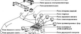
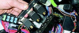
Most of the relays, as well as the voltage regulator, are located in the engine compartment.
Location of the VAZ 2106 relay in the engine compartment
If it fails, it is recommended to replace the relay assembly, since if the winding is burned out, or the relay contacts are severely burnt, it is difficult to properly restore its functionality.
This is how the VAZ 2106 relays are located in the engine compartment: 1 – battery charge indicator relay; 2 – relay for turning on the high beam headlights; 3 – relay for turning on low beam headlights.
The relay for turning on the high and low beam headlights and the relay for turning on the radiator fan of the engine cooling system are of the same type (90.3747-10 or 113.3747-10), are interchangeable and are replaced in the same way
Not protected by fuses
- Starter
- Ignition system
- Battery charging circuit
- Low beam relay
- High beam relay
Thermobimetallic fuses
- Windshield wiper (since 1985) - integrated into the electric motor circuit
- Window lifters - integrated into the electric motor circuit
Relay
- Hazard warning and turn signal relay ('77-'85 - 23.3747
, '85-'01 -
231.3747
) - mounted on the front panel behind the instrument cluster. - Battery charge indicator lamp relay (PC 702) - secured to the right side member mudguard in the engine compartment with two self-tapping screws. A ground tip is installed under one of the screws.
- The low beam headlight relay - B
(113.3747, 90.3747 (RS 527)) - is mounted on the mudguard of the right side member in the engine compartment. - Headlight high beam relay - A
(113.3747, 90.3747 (RS 527)) - is mounted on the mudguard of the right side member in the engine compartment. - Windshield wiper relay (PC 514) - installed under the instrument panel on the driver's side and attached to the body with two screws.
- Voltage regulator (PP 380, RS 702, RS 121, 59.3702, 592.3702, 591.3702, 591.3702-01) - mounted on the mudguard of the left side member in the engine compartment.
- Sound signal relay (PC 528) - mounted on the mudguard of the left side member in the engine compartment.
- Cooling system fan relay (90.3747-10, 113.3747-10) - mounted on the left side member splash guard in the engine compartment. (not installed since 2000)
- Parking brake warning lamp relay (PC 492) - located behind the instrument panel. (Not applicable since 1994)
- Rear window heating relay - located behind the instrument panel.
VAZ 2106: fuses. VAZ 2106 fuse diagram
On VAZ-2106 cars, fuses were used of the old type, cylindrical. They protect electrical circuits, but the design has many disadvantages.
The location of the fuse box is good - near the driver’s left foot, away from moisture and direct sunlight. If we compare it with the VAZ-2109, in which the mounting block is located in the engine compartment, the six has a clear advantage.
Every VAZ-2106 owner needs to know which fuse protects which circuit.
Purpose of main unit fuses
The fuses are located on the main (upper) and additional (lower) ones:
- F1, designed for a maximum current of 16 A, is necessary to protect the power circuits of the cigarette lighter, sound signal, interior lamps, clocks, brake lights, and light warnings about open doors.
- F2, response current 8 A, allows you to protect the circuits of the windshield wiper and its relay, the electric washer motor and the heater.
- F3, 8 Amperes, protects the power supply circuit of the left high beam headlight and the light control lamp.
- F4, current 8 A, right headlight (high beam).
- F5, F6, 8 Amperes – left and right headlights (low beam), respectively.
- F7 – side lights (right rear and left front), light in the luggage compartment, license plate illumination, instrument cluster, cigarette lighter. Rated current 8 A.
- F8 – side lights (left rear and right front), lamps under the hood and control panel on the dashboard.
- F9 – designed to protect the power circuits of oil pressure, fluid temperature, gasoline level, and reserve lamp indicators. It also supplies power to the warning lamp, which signals that the handbrake has been applied, as well as an emergency level of brake fluid, a lack of battery charge, and the closing of the air damper. The XX solenoid valve, tachometer, reverse lamps, glove compartment lights, rear window defroster relay are also powered from this fuse.
- Fuse F10 supplies power to the voltage regulator. Rating – 8 Amperes.
- F11, F12, F13 – reserve.
Additional fuse block
- F14 – fuse for protecting the power circuit of the rear window heater. Rated operating current 16 A.
- F15 – electric motor for cooling the radiator. Current 16 A.
- F16 – hazard warning lights and direction indicators.
Wiper relay and fuse
VAZ-2106 fuses protect power circuits by controlling electromagnetic relays. One of the main ones is the windshield wiper relay, which is powered through fuse F2.
With its help, the wipers do not work constantly, but intermittently. It is much more effective to control low-current circuits than power ones.
The relay is located under the dashboard, on the left side of the car interior. Replacement is carried out in this order:
- Remove the seal on the driver's door pillar flange.
- Pry up the upholstery and remove it.
- Remove the holders installed on the side. Be sure to install new holders during installation.
- Bend back the sound insulation.
- Disconnect the block with the relay wires from the main harness. The connector is located at the bottom of the dashboard.
- Remove the two screws that secure the relay housing to the body.
After removing the old relay, install a new one in its place. The work is performed in reverse order. If replacing the VAZ-2106 fuses responsible for the operation of the windshield wiper did not help, then be sure to check the integrity of the wires and relays.
Direction indicators and hazard warning lights
There is one drawback in the car - the VAZ-2106 fuses are located in the passenger compartment, but the relays are scattered throughout the engine compartment. The breaker responsible for the operation of the direction indicators is located on the partition in the engine compartment opposite the dashboard. Main breakdowns of the alarm system:
- Fuse F16 is faulty. Check it with a multimeter and replace if necessary.
- Frequent turning on of the control lamp indicates that one of the repeaters or indicators is faulty.
- A relay malfunction leads to complete failure of the warning system.
- If the alarm button breaks down, it does not allow the indicators to turn on.
To replace, you need to remove the instrument panel, then unscrew the nut using a 10mm socket. After this, disconnect the wire block and remove the relay. Install the new one in reverse order.
Turning on the headlights
To turn on the high and low beams, two relays are used, which are installed in the engine compartment, above the right mudguard. Removing the relay is very simple - just disconnect all the wires from it and unscrew the self-tapping screw with a Phillips screwdriver. Together with the bracket, the end of the ground wire is also attached to the body with a self-tapping screw.
Be sure to mark the location of the wires before disconnecting them from the electromagnetic relay. You can disconnect the wires one at a time and immediately install them on a new relay.
The replacement procedure is simple, so it can be completed in a few minutes. If the relay does not receive voltage, then the fuse links need to be replaced.
In the VAZ-2106 fuse circuit, elements F3-F7 are used to protect the power circuits of the low and high beam lamps.
Turns relay
An indicator breaker with 3 or 4 contacts is located behind the instrument panel on the partition of the engine compartment. The rating of the light bulbs connected to the circuit should be 21 A. It looks like a rectangle.
Generator fuse and relay diagram
To check the condition, you need to get to the thermostat, since it is located directly below it. It is attached to the generator with two screws and connected with a wire that often frays. This is true for the VAZ 2106 modification with an injector. Without it, the power supply to the generator excitation winding will be unstable.
Starter relay
You can easily find the retractor, as well as remove it yourself. You need to disassemble the starter using screwdrivers. You will need to correctly install a new one in its place.
High and low beam fuse and relay
The elements F5 and F6 are responsible for the first one, and F3 and F4 are responsible for the distant one. The power of each is 8 A.
Handbrake relay VAZ 2106: where is it located
On the parking brake.
Tachometer
It is protected by fuse F9 rated 8 A.
Radio tape recorder
It is connected to one of the backup fuses.
Washer
The protective element is marked F2 and is rated at 8 A.
Distributor
Can be found near his slider at the top.
Parking brake
The relay is located behind the dashboard of the VAZ 2106, has a round shape and is made of aluminum.
Fuse F1
If the interior lighting or socket does not work, the 16 Amp fuse element that is responsible for them may have burned out.
How does a standard six fuse work?
Let's consider the design and operating principle of a standard “six” fuse-link. Unlike a modern knife fuse, it consists of only two parts: a ribbed plastic cylinder that acts as a body, and the insert itself, made of low-melting metal, located outside it. The contacts of the VAZ-2106 mounting block are made of copper (brass) and also have an open arrangement. From the point of view of electrical engineering, such a design cannot be called either reliable or safe, since all conductive elements, in fact, are not protected in any way.
Additional fuse block
- F14 – fuse for protecting the power circuit of the rear window heater. Rated operating current 16 A.
- F15 – electric motor for cooling the radiator. Current 16 A.
- F16 – hazard warning lights and direction indicators.
When connecting a new unit, be sure to use the VAZ-2106 fuse diagram. This will prevent the elements from being mixed up.
Types of fuses
A competent choice of fuses will save VAZ-2106 owners from serious problems. Incorrectly selected parts can cause problems such as vehicle fires. When choosing these parts, you should pay attention to the current strength in them, which is expressed in Amperes. Fuses of different amperages have corresponding digital markings and also differ from each other in color. For example, brown ones have a rating of seven and a half Amperes, blue ones - 16A, green ones - 20A. It is important that the ratings of each part coincide with the manufacturers' recommendations.
Fuse box problems and troubleshooting
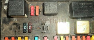
On the VAZ "six" fuses are installed in two blocks - the main and additional ones. Structurally, they are made of a plastic case, fusible inserts and holders for them.
VAZ 2106 fuse blocks: 1 - main fuse block; 2 - additional fuse block; F1 - F16 - fuses
Both devices are located in the cabin to the left of the steering column under the dashboard.
The fuse box on the VAZ 2106 is installed to the left of the steering column under the dashboard
How to identify a blown fuse
When a “six” has a malfunction with one of the electrical appliances (windshield wipers, heater fan, etc.), the first thing you should pay attention to is the integrity of the fuse links. Their serviceability can be checked in the following ways:
- visually;
- multimeter.
Visual inspection
The design of the fuses is such that the condition of the fuse link can be used to determine the operability of the part. The cylindrical elements have a fusible connection located outside the housing. Even a car enthusiast without experience can determine its destruction. As for the flag fuses, their condition can be assessed by looking through the light. A burnt-out element will have a broken fusible link.
Determining the integrity of the blade fuse is quite simple, since the element has a transparent body
Diagnostics with a control and a multimeter
Using a digital multimeter, the functionality of the fuse can be checked by voltage and resistance. Let's consider the first diagnostic option:
- We select a limit on the device to check the voltage.
- We turn on the circuit being diagnosed (lighting devices, wipers, etc.).
- We touch the fuse contacts one by one with the probes of the device or control panel. If there is no voltage at one of the terminals, it means that the element being tested has failed.
Details about instrument panel malfunctions: https://bumper.guru/klassicheskie-modeli-vaz/elektrooborudovanie/panel-priborov/panel-priborov-vaz-2106.html
Table: VAZ 2106 fuse ratings and circuits they protect
| Fuse No. (rated current) | Names of equipment of protected electrical circuits |
| F 1 (16 A) | Horn Socket for portable lamp Cigarette lighter Brake lamps Clock Interior lamps |
| F 2 (8 A) | Wiper relay Heater motor Windshield wiper and washer motors |
| F 3 (8 A) | High beam (left headlights) High beam warning lamp |
| F 4 (8 A) | High beam (right headlights) |
| F 5 (8 A) | Low beam (left headlight) |
| F 6 (8 A) | Low beam (right headlight). Rear fog light |
| F 7 (8 A) | Side light (left sidelight, right rear light) Trunk lamp Right license plate light Instrument lamps Cigarette lighter lamp |
| F 8 (8 A) | Side light (right sidelight, left rear light) Left license plate light Engine compartment lamp Side light indicator lamp |
| F 9 (8 A) | Oil pressure gauge with indicator lamp Coolant temperature indicator Fuel level indicator Battery charge indicator lamp Turn indicators and corresponding indicator lamp Carburetor choke indicator Rear window heating relay coil |
| F 10 (8 A) | Voltage regulator Generator field winding |
| F 11 (8 A) | Spare |
| F 12 (8 A) | Spare |
| F 13 (8 A) | Spare |
| F 14 (16 A) | Rear window heating element |
| F 15 (16 A) | Cooling fan motor |
| F 16 (8 A) | Direction indicators in hazard warning mode |
Repair and replacement of fuses
The fuse box diagram will help you determine what you need to purchase. Factory spare parts can be purchased in specialized stores that service and sell auto parts at VAZ. The repair scheme is as follows: initially, the cause of the breakdown is determined and it is determined what will be required: replacement of the element or the entire module.
When a fuse trips, you should not rush: the layout of the elements of the safety module will help you figure out which circuit protects this element. Later, you need to determine the cause of the short circuit and try to eliminate it. After repair, having insulated the wires, you can insert a new fuse.
replaced in this way.
| Actions | Nuances |
| Disconnect the battery. Open the driver's door slightly. | Using a screwdriver, lift the two fasteners that fasten the decorative interior upholstery. |
| After the module appears, use a Phillips screwdriver to unscrew its fasteners. | You need to watch the wires so that they do not fly out of the terminals. |
| After unscrewing the module, it is taken to the bottom. | This is done carefully so that the wiring does not break. |
| Jumpers are installed exclusively on wiring that supplies voltage from the engine compartment. | The jumper is not connected after the fuse, because then voltage will flow through one element to several parts of the equipment. |
| The jumper installation diagram is as follows. | 3 and 4, 5 and 6, 7 and 8, 9 and 10, 11 and 12, 12 and 13. |
| Then, one by one, remove the wire from the old module and mount it on the one being installed. | Do this with all wires. |
Having finished, they check whether the circuit is connected correctly. To do this, turn on the voltage and pull out the fuse that matches the device. The easiest way is to turn on the headlights and remove the corresponding component of the safety module. When the headlight is off, the connection is correct. Each of the module fuses is monitored in a similar manner.
When the equipment operates with the fuse removed, it means that the jumper is installed incorrectly and needs to be replaced. It will be necessary to recheck the operation of the entire circuit to identify and eliminate incorrect connections.
Reset the circuit to the fuses of the VAZ 2106, which is responsible for what. Thank you.
1) 1. Horn, 2. Power socket, 3. Cigarette lighter, 4. Clock, 5. Brake light, 6. Lights;
2) 1. Wiper relay, 2. Heater motor, 3. Wiper and washer motors;
3) 1. Left high beam, 2. High beam signal lamp;
4) High beam right headlights;
5) Low beam left headlight;
6) 1. Low beam right headlight, 2. Rear fog light;
7) 1. Dimensions (left sidelight, right rear light), 2. Trunk light, 3. Cigarette lighter light, 4. Right license plate light, 5. Instrument lights;
1. Dimensions (right sidelight, left rear lamp), 2. Left license plate lamp, 3. Engine compartment lamp, 4. Signal lamp for turning on the dimensions;
9) 1. Oil pressure lamp, 2. Coolant temperature indicator, 3. Fuel level indicator, 4. Battery charge lamp, 5. Turn signal lamps, 6. Relay coil for rear window heating relay, 7. Air position indicator. carburetor dampers;
10) 1. Voltage regulator, 2. Generator excitation winding;
11) Fuses F11, F12, F13 - backup, for additional devices;
12) Rear window heating element;
13) Cooling system fan electric motor;
14) Direction indicators in hazard warning mode.
The VAZ 2106 fuse box is quite simple and does not contain any diodes, circuit boards or other bells and whistles inherent in more modern cars.
Blowing fuses is quite common. But there is no need to rush to change it. First you need to find out what this fuse is responsible for (the picture will help you with this) and find out why it burned out. Once the cause of the short circuit has been identified and eliminated, a new fuse can be installed.
Changing fuses with coins, screws and bugs is absolutely not worth it , this significantly increases the risk of a fire. Loading many devices (heating, radio, etc.) onto one fuse is also unnecessary.
It may also be useful to know the answers to the following questions :
Quite often, VAZ-2106 car owners have to repair electrical equipment in their car. And such a breakdown is most often caused by malfunctions in the fuse circuit, which can simply lose contact with the plate conducting the current.
Many car owners have already been able to see from their own experience that the design of fuses, to put it mildly, is not very reliable, because the elements can fail as soon as the resistance in the circuit increases a little. Then they begin to get very hot, which will lead to deterioration and even complete loss of contact.
In addition, it is worth noting that damage can also occur if the pressing force of the plate that holds the fuse weakens. Moreover, if the breakdown is caused by this reason, then it will be quite dangerous. The fact is that if there is a bad contact on the fuse, the element may simply not work when a short circuit occurs, and it will inevitably heat up. As a result, a failed element can cause the entire circuit to catch fire, and at the most inopportune time.
It is possible to prevent such a problem from arising if you monitor the external state of the analyzed elements, and replace failed VAZ-2106 fuses in a timely manner and, of course, understand which one is responsible for what.
VAZ 2106 fuse box pinout, diagram
If you have any problems with electrical equipment: the low or high beams have disappeared or are not working, the turn signals, stove, cigarette lighter, fan, wipers are not working, the signal has disappeared, etc., then this could all be the reason that the fuse has blown. This means it needs to be replaced.
To do this, you need to know the location of the mounting block. And it is located under the steering wheel, on the left side. In order to understand what the VAZ 2106 fuses are responsible for, you need to look at the simple pinout of the old fuse block (FB) and see the description below.
Table “VAZ 2106 fuse designations”
Fuse number Current, AZ what corresponds to
| 1 | 16 | 1. Lamps 2. Horns 3. Power socket 4. Cigarette lighter 5. Rear lamps 6. Front door open warning lamps 7. Clock |
| 2 | 8 | 1. Windshield wiper and wiper relay 2. Wiper motor 3. Heater motor |
| 3 | 8 | Left headlight (high beam) and high beam indicator lamp |
| 4 | 8 | Right headlight (high beam) |
| 5 | 8 | Left headlight (low beam) |
| 6 | 8 | Right headlight (low beam) |
| 7 | 8 | 1. Left front marker 2. Right rear marker 3. Trunk light 4. License plate light 5. Instrument lights 6. Cigarette lighter light |
| 8 | 8 | 1. Right front marker 2. Left rear marker 3. License plate light 4. Engine compartment lamp 5. Side light indicator lamp |
| 9 | 8 | 1. Oil pressure sensor with warning lamp 2. Coolant temperature sensor 3. Fuel level with reserve warning lamp 4. Parking brake activation and brake fluid level warning lamps 5. Turn signals and corresponding warning lamps 6. Battery charge warning lamp 7. Control lamp carburetor choke control lamp 8. Carburetor shut-off valve 9. Tachometer 10. Reversing lamps 11. Glove compartment lamp 12. Rear window heating relay coil |
| 10 | 8 | 1. Voltage regulator. 2. Generator excitation winding |
| 11 | 8 | Spare |
| 12 | 8 | Spare |
| 13 | 8 | Spare |
| 14 | 16 | Heated rear window |
| 15 | 16 | Engine cooling fan |
| 16 | 8 | "Emergency" |
Scheme
The black box and relay are first checked and carefully inspected, and only then replaced with new ones. On the inside of the lid there is a diagram of the box that anyone can use.
Attention! On the “six” the fuses go from left to right. This can be seen in the provided diagram.
- (power - 16A) - responsible for sound, front door alarm lights, lamps, cigarette lighter, clock;
- (power - 8A) - controls the relay, heater, windshield electric motor, windshield wipers;
- — controls the high-beam headlights on the left side and the control lamp;
- — controls the high-beam headlights on the right;
- — responsible for the operation of the left low beam headlights;
- — controls the right low-beam headlights;
- — responsible for the left front and right rear dimensions, and for the lighting of the rooms;
- — monitors the operation of the right front and left rear lights, as well as the engine compartment lighting and warning light;
- — responsible for rear traffic lights, turn signals, luggage compartment lighting, oil pressure indicator, brake light, tachometer;
- — controls the voltage regulator;
- — backup fuses (RP);
- - RP;
- - RP;
- — controls the operation of the rear window electric heating;
- — controls the operation of the fan and engine cooling;
- — is responsible for the operation of emergency indicators.
Flat fuses are installed on the euro fuse blocks on the VAZ-2106 (new type boxes). The first of them has a power of 16 A, all the others - 8A. The connection diagram for the VAZ 2106 euro fuse box is given below.
- — responsible for the sound signal, interior lighting, brake lights, clock and cigarette lighter;
- — windshield washer, heater motors, windshield wiper relay;
- — high beam on the left and high beam indicator;
- — high beam on the right;
- — low beam on the left;
- — Low beam on the right and rear fog lamp;
- — left front and right rear dimensions, luggage compartment lighting, license plate lighting, cigarette lighter lighting, instrument lighting;
- — right front and left rear dimensions, engine compartment lighting;
- — indicators for oil pressure, cooling fluid temperature, fuel level, rear heated glass, turn signals;
- — regulates the generator voltage;
- — reserve (R);
- — Electrically heated glass at the rear;
- - cooling system;
- - emergency mode.
The diagram of a regular VAZ 2106 fuse box and the diagram of the new model box are very similar. The difference is in the details themselves. The usual “black box” uses blade fuses, while the new type unit uses flag fuses.
Relay VAZ 2106
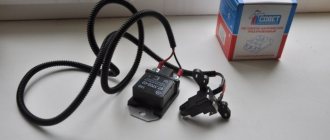
- Voltage regulator, which is responsible for proper charging of the battery. Located on the left mudguard.
- The wiper relay is located on the left side, under the instrument panel.
The video below clearly shows where which relay is located.
Problems with the mounting block and their solution
Many owners of "sixes" are faced with the problem of frequent power surges. It can be caused either by a malfunction of the generator or voltage regulator, or by problems with the mounting block. If you have established that it is the cause of the problems, do not rush to replace it with a similar one, just a new one. Better take a closer look at the mounting block from GAZ-3110. How is it better? The fact that it will allow installing fuses on the VAZ-2106, which are equipped with “installers” of modern cars. They are easier to buy and more reliable. In addition, the Volga mounting block is much more compact than the “six” one. It is made in the form of a single strip, accommodating only 12 fuse links.
"Euroblock" VAZ 2106 (new model), diagram
Below is a picture of what the Eurobloc looks like in real life.
Replacing the VAZ 2106 fuse box with a “Euroblock”
And finally, for those who don’t know how to replace the old model with a “Euroblock”, the following information. There is nothing complicated here.
You just need to follow the instructions below:
- First you need to disconnect the minus from the battery.
- Use a 10mm wrench to unscrew the old power supply. In this case, the wires are not disconnected.
- According to the diagram above, wires and jumpers are installed.
- It is important to install jumpers only on those wires that carry voltage from the engine compartment.
- Jumpers are installed between pins 3-4, 5-6, 7-8, 9-10, 11-12.
- Next, the wires are removed one by one from the old device and attached to the Euroblock.
- At the end, check that the connection is correct (for example, with the low beam on, if you pull out the 5th fuse, the left headlight should go out).
- All other circuits are also checked.
The video below clearly shows how to replace an old power supply with a Euroblock.
How to identify a blown fuse
- visual inspection;
- diagnostics with a multimeter.
Visual inspection
It is necessary to check the integrity of the metal partition of the element. If it is broken, then the insert is burned out.
Diagnostics with a control and a multimeter
When an element burns out, the integrity of the jumper is not always compromised. It wouldn't hurt to check with a multimeter. The probe is applied to the fuse, the device is turned on, and if it shows resistance other than 0 Ohm, then the element is broken.
Removal and replacement process
There is nothing difficult in the process of changing power supply parts, so we will not describe this process. But we will tell you how to replace an old-style power supply with a new-style device.
- First of all, disconnect the battery. Now open the driver's door and use a screwdriver to pry out the two fasteners securing the decorative interior trim. Move it to the side and you will see a block. Using a Phillips screwdriver, unscrew the screws securing the power supply. Do this carefully so that the wires do not fly off the terminals in the process.
- Once the power supply is unscrewed, move it down. But do not pull it too hard to avoid breaking the wires. Note! Jumpers must be installed on those wires through which voltage comes from the engine compartment. Do not connect the jumper after the fuse itself, otherwise this will result in voltage passing through one part to power several electrical components.
- The order of installation of jumpers should be as follows: 3-4, 5-6, 7-8, 9-10, 11-12, 12-13.
- Now you need to remove each wire one by one, starting with the first fuse from the old power supply, and mount it on the new one. Perform this operation with each contact, until the very last wire. When all the contacts are in place, you should check whether you did everything correctly. In particular, you need to turn on the voltage source and remove the corresponding fuse. If the device stops functioning, then all actions were performed correctly. For example, turn on the low beam headlights and remove one of the power supply elements responsible for the left or right headlight. If it goes out, then you did everything right.
- Check each fuse in the same way. If, when dismantling the element, the device continues to work, then the jumper is most likely installed incorrectly, so double-check the connection diagram.
This completes the replacement of the power supply with a new type device. As you can see, there is nothing difficult about this, but if you are not sure that you will do everything correctly or cannot distinguish the blue wire from the red or green, then entrust this matter to an electrician.
Sources
- https://granta-service.ru/diagnostika/predohraniteli-vaz-2106-kakoj-i-za-chto-otvechaet.html
- https://vsepredohraniteli.ru/lada/vaz-2106.html
- https://knigaproavto.ru/shemy/vaz/21032106/496-predohraniteli-vaz-2106.html
- https://rus-avtomir.ru/predohraniteli/rele-vaz-2106
- https://saturn-lada.ru/novosti/raspinovka-predohranitelej-vaz-2106.html
- https://bumper.guru/klassicheskie-modeli-vaz/elektrooborudovanie/predohraniteli-vaz-2106.html
- https://VazNeTaz.ru/publ/remont_vaz_samomu/predoxraniteli-vaz-2106-sxemy-kakoj-za-chto-otvechaet.html
Location and electrical diagram
The power supply itself consists of two lines with fuses, which is installed in the car interior and attached to the body with two nuts. In particular, it is located on the driver's side under the instrument panel. Below is a diagram of the device, as well as the purpose of each element.
As you can see, almost all circuits of a domestically produced car are protected using fusible devices. However, there are exceptions here too. In particular, we are talking about:
- starter retractor relay - it is missing;
- the power circuit of the relay coil, which ensures the operation of the radiator fan of the cooling system, is also not protected;
- the ignition coil is also not protected by a relay;
- If your car has an old-style power supply, then it does not have a power supply circuit for the switch and a Hall sensor.
The element installed in the power supply is designed for a certain voltage in the wiring. This voltage is calculated using a simple formula - the voltage of all energy consumers in the wire must be multiplied by the reserve number, ranging from 1.2 to 1.5. So what's the purpose? In order for the operation to be stable, the nominal values of the block elements must match.
It should be added that very often owners of 2106 make mistakes by using an ordinary coin instead of a fusible device. It is better not to do this, since a short circuit may occur in your car at any time. Therefore, old-style power supplies, like any other machine component, also require periodic maintenance. Due to design features, that is, weak power supply holders or tips that regularly oxidize, you may notice the contact part burning.
Thus, due to the increased contact resistance, overheating occurs and the contact condition of the element deteriorates. This may result in additional problems with the vehicle's wiring. To prevent this from happening, you should periodically, at least twice a year, inspect the power supply unit as a whole. Clean the mounting sockets, inspect the power supply and promptly replace failed fuses.
But this all applies to old-style power supplies. Some owners of these car models, taking into account the periodic problems with the old-style power supply, change it to a new one.